Type Of Constant Velocity Universal Joint With The Spline Slip Structure
Cheng; Fuying ; et al.
U.S. patent application number 16/039687 was filed with the patent office on 2019-03-14 for type of constant velocity universal joint with the spline slip structure. The applicant listed for this patent is Zhejiang CFMOTO Power Co., Ltd.. Invention is credited to Fuying Cheng, Li Jiajun, Zhenxiang Kuang.
| Application Number | 20190078623 16/039687 |
| Document ID | / |
| Family ID | 65630866 |
| Filed Date | 2019-03-14 |


| United States Patent Application | 20190078623 |
| Kind Code | A1 |
| Cheng; Fuying ; et al. | March 14, 2019 |
Type Of Constant Velocity Universal Joint With The Spline Slip Structure
Abstract
A type of constant velocity universal joint has the spline slip structure, including the steel wire retaining ring and the star-shaped sleeve which are both mounted on a common axis, and the steel wire retaining ring limiting device. The said steel wire retaining ring limiting device is a groove arranged on the said star-shaped sleeve and used for holding the said steel wire retaining ring. The said steel wire retaining ring may be elliptic or circular. The movement in the radial direction of the steel wire retaining ring will be limited by the groove on the star-shaped sleeve and there occurs a certain contraction, in addition to appropriate the chamfer angle of the groove, so it is very convenient to remove the spline shaft from the star-shaped sleeve.
| Inventors: | Cheng; Fuying; (Hangzhou, CN) ; Kuang; Zhenxiang; (Hangzhou, CN) ; Jiajun; Li; (Hangzhou, CN) | ||||||||||
| Applicant: |
|
||||||||||
|---|---|---|---|---|---|---|---|---|---|---|---|
| Family ID: | 65630866 | ||||||||||
| Appl. No.: | 16/039687 | ||||||||||
| Filed: | July 19, 2018 |
| Current U.S. Class: | 1/1 |
| Current CPC Class: | F16D 3/2245 20130101; F16D 3/223 20130101; F16D 2003/22313 20130101; F16D 2250/0084 20130101; F16D 2003/22326 20130101; F16D 2003/22309 20130101; F16D 3/06 20130101; F16D 2300/12 20130101 |
| International Class: | F16D 3/2245 20060101 F16D003/2245 |
Foreign Application Data
| Date | Code | Application Number |
|---|---|---|
| Jul 19, 2017 | CN | 201720880127.6 |
| Jul 19, 2017 | CN | 201720880153.9 |
Claims
1. A type of constant velocity universal joint with the spline slip structure, including the circular steel wire retaining ring and the star-shaped sleeve which are both mounted on a common axis, is characterized in that it also includes the steel wire retaining ring limiting device. The said steel wire retaining ring limiting device is a groove arranged on the said star-shaped sleeve and used for holding the said circular steel wire retaining ring.
2. According to claim 1, the said constant velocity universal joint with the spline slip structure is characterized in that the chamfer angle is arranged on the said groove.
3. According to claim 1, the said constant velocity universal joint with the spline slip structure is characterized in that the said groove is the arc groove.
4. According to claim 1, the said constant velocity universal joint with the spline slip structure is characterized in that the said groove is the L-shaped groove.
5. According to claim 1, the said constant velocity universal joint with the spline slip structure is characterized in that the said groove is formed by horizontal plane and inclined plane.
6. A type of constant velocity universal joint with the spline slip structure, including the steel wire retaining ring and the star-shaped sleeve which are both mounted on a common axis, is characterized in that it also includes the steel wire retaining ring limiting device. The said steel wire retaining ring limiting device is a groove arranged on the said star-shaped sleeve and used for holding the said steel wire retaining ring. The said steel wire retaining ring is elliptic.
7. According to claim 6, the said constant velocity universal joint with the spline slip structure is characterized in that the chamfer angle is arranged on the said groove.
8. According to claim 6, the said constant velocity universal joint with the spline slip structure is characterized in that the said groove is the arc groove.
9. According to claim 6, the said constant velocity universal joint with the spline slip structure is characterized in that the said groove is the L-shaped groove.
10. According to claim 6, the said constant velocity universal joint with the spline slip structure is characterized in that the said groove is formed by horizontal plane and inclined plane.
Description
CROSS-REFERENCE TO RELATED U.S. APPLICATION(S)
[0001] None.
FIELD OF THE INVENTION
[0002] The present invention relates to the technical field of universal joint, particularly to a type of constant velocity universal joint with the spline slip structure.
BACKGROUND OF THE INVENTION
[0003] The steel wire retaining ring is arranged on the constant velocity universal joint with the spline slip structure, and it can be moved in the radial direction under the free state; so it is very difficult for maintenance and disassembling, and it is possible to cut off the retaining ring before it can be removed, or even the retaining ring is unable to be removed normally.
[0004] Therefore, how to provide a type of constant velocity universal joint with the spline slip structure to facilitate removing the spline shaft from the star-shaped sleeve is technical defect which urgently need to be solved for those skilled in the art.
BRIEF SUMMARY OF THE INVENTION
[0005] In view of this, the purpose of the present invention is to provide a type of constant velocity universal joint with the spline slip structure to facilitate removing the spline shaft from the star-shaped sleeve.
[0006] In order to achieve the above object, the present invention provides the following technical schemes:
[0007] A type of constant velocity universal joint with the spline slip structure includes the steel wire retaining ring and the star-shaped sleeve which are both mounted on a common axis, and the steel wire retaining ring limiting device. The said steel wire retaining ring limiting device is a groove arranged on the said star-shaped sleeve for holding the said steel wire retaining ring. The said steel wire retaining ring is circular in one embodiment and elliptic in another embodiment.
[0008] Preferably, the above groove is provided with the chamfer angle.
[0009] Preferably, the above groove is the arc groove.
[0010] Preferably, the above groove is the L-shaped groove.
[0011] Preferably, the above groove is formed by the horizontal plane and the inclined plane.
[0012] A type of constant velocity universal joint with the spline slip structure provided by the present invention includes the steel wire retaining ring and the star-shaped sleeve which are both mounted on a common axis, and the steel wire retaining ring limiting device. The said steel wire retaining ring limiting device is a groove arranged on the said star-shaped sleeve for holding the said steel wire retaining ring. The said steel wire retaining ring is circular in one embodiment and elliptic in another embodiment. The movement in the radial direction of the steel wire retaining ring will be limited by the groove on the star-shaped sleeve and there occurs a certain contraction, in addition to appropriate the chamfer angle of the groove, so it is very convenient to remove the spline shaft from the star-shaped sleeve.
BRIEF DESCRIPTION OF THE DRAWINGS
[0013] In order to describe the technical scheme more clearly in the existing technology or the embodiment of the present invention, the drawings required for the implementation of the existing technology or the embodiment of the present invention are briefly introduced in the following, obviously, the drawings below are some embodiments of the present invention, for the ordinary technical personnel in the art, you can also get other drawings according to these drawings at the premise of without giving creative labor.
[0014] FIG. 1 is the schematic view showing the structure of the steel wire retaining ring being arranged on the constant velocity universal joint with the spline slip structure provided by the embodiment of the present invention.
[0015] FIG. 2 is the side schematic view showing the structure of the steel wire retaining ring being arranged on the constant velocity universal joint with the spline slip structure provided by the circular embodiment of the present invention.
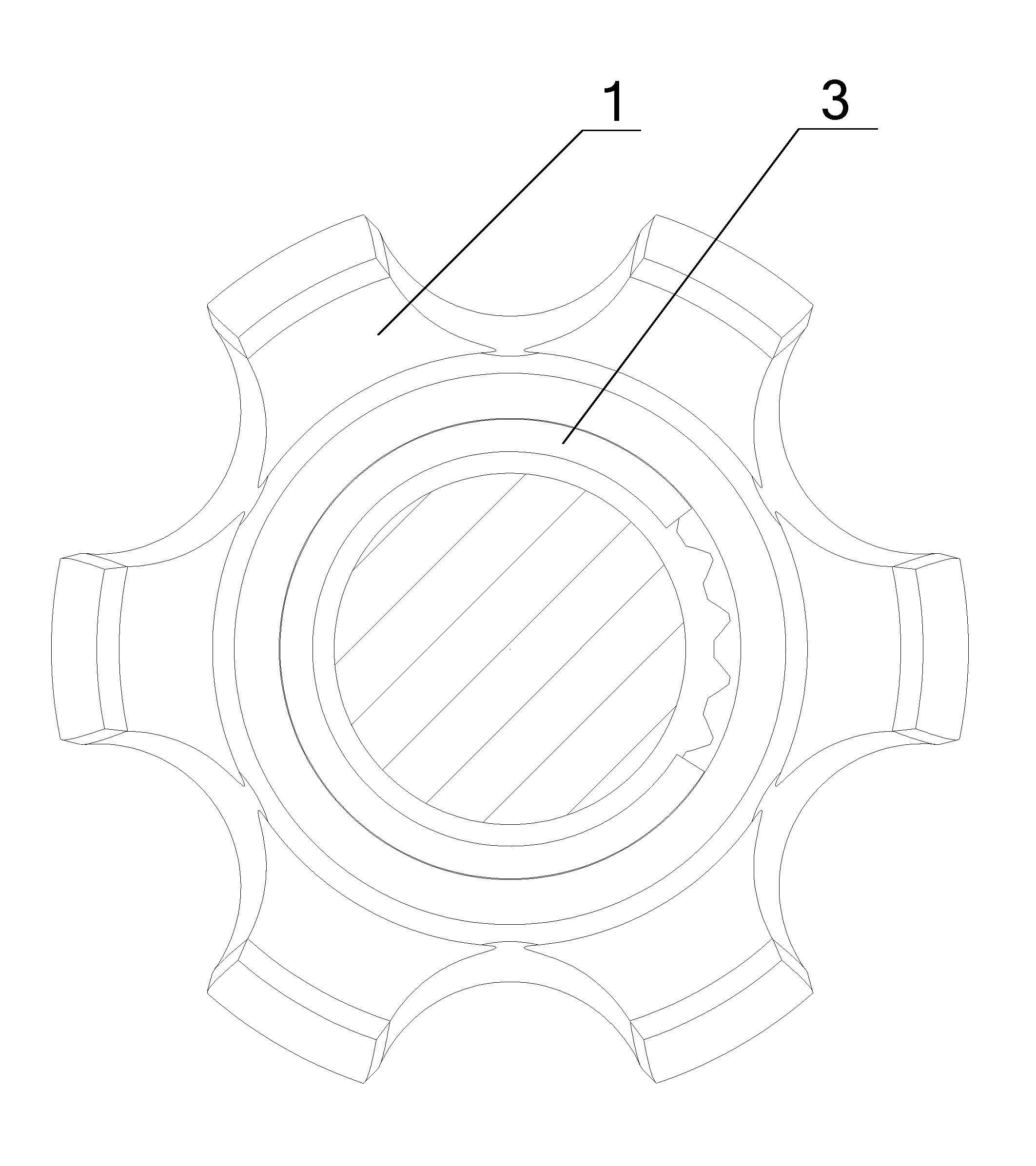
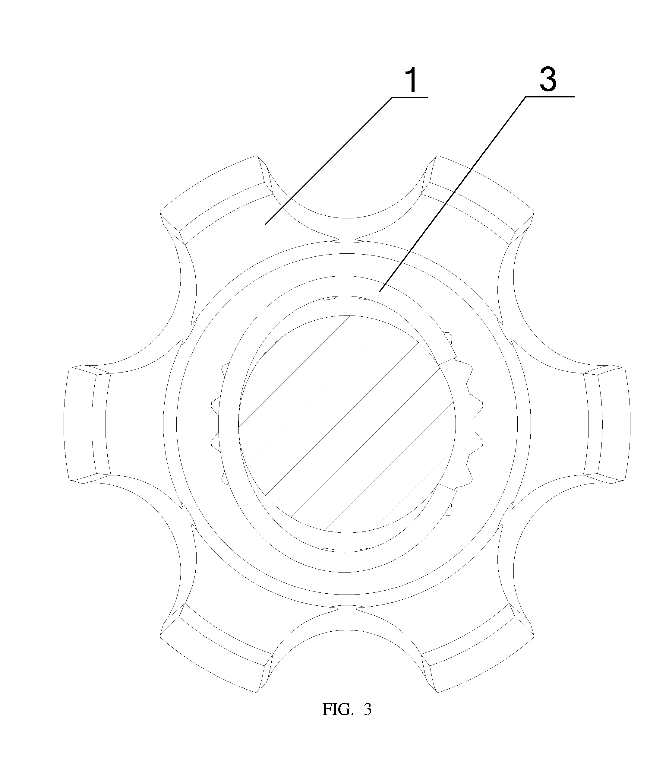
[0016] FIG. 3 is the side schematic view showing the structure of the steel wire retaining ring being arranged on the constant velocity universal joint with the spline slip structure provided by the elliptic embodiment of the present invention.
[0017] FIGS. 1-3: The star-shaped sleeve 1, the groove 2, the steel wire retaining ring 3, the chamfer angle 4.
DETAILED DESCRIPTION OF THE PREFERRED EMBODIMENTS
[0018] To make the purpose, technical scheme and advantages of the embodiment of the present invention more clear, technical scheme of the embodiment of the present invention is clearly and completely described in the following combined with the accompanying drawings of the embodiment of the present invention; obviously, the embodiment of the present invention is a part of the embodiments, not all of the embodiments of the present invention. Based on the embodiment of the present invention, all other embodiments Which the ordinary technical personnel in the art obtain at the premise of without giving creative labor are also deemed to fall into the protection scope of the present invention.
[0019] Referring to FIGS. 1-3. FIG. 1 is the schematic view showing the structure of the steel wire retaining ring being arranged on the constant velocity universal joint with the spline slip structure provided by the embodiment of the present invention. FIG. 2 is the side schematic view showing the structure of the steel wire retaining ring being arranged on the constant velocity universal joint with the spline slip structure provided by the circular embodiment of the present invention. FIG. 3 is the side schematic view showing the structure of the steel wire retaining ring being arranged on the constant velocity universal joint with the spline slip structure provided by the elliptic embodiment of the present invention.
[0020] A type of constant velocity universal joint with the spline slip structure provided by the present invention includes the steel wire retaining ring 3 and the star-shaped sleeve 1 which are both mounted on a common axis, and the steel wire retaining ring limiting device. The steel wire retaining ring limiting device is a groove 2 arranged on the star-shaped sleeve 1 for holding the steel wire retaining ring 3. The steel wire retaining ring 3 is circular in the first embodiment and elliptic in the second embodiment. The movement in the radial direction of the steel wire retaining ring 3 will be limited by the groove 2 on the star-shaped sleeve 1 and there occurs a certain contraction, in addition to appropriate the chamfer angle of the groove, so it is very convenient to remove the spline shaft from the star-shaped sleeve.
[0021] Further optimization of the above technical scheme, the groove 2 is provided with chamfer angle 4, so it is more convenient for disassembling. Wherein, the groove 2 can be the arc groove or L-shaped groove. Of course, the groove 2 can also be formed by the horizontal plane and the inclined plane.
[0022] The above descriptions of the disclosed embodiment enable professional and technical personnel in the art to achieve or use the present invention. Obviously, the professional and technical personnel in the art will make a plurality of modifications to these embodiment, the general principles defined in this article may be achieve in the other embodiment without departing from the spirit or essential attributes of the present invention. Therefore, this invention will not be limited to the embodiment shown in this article, but to conform to the maximum extent of principles and new features that are disclosed in this article.
* * * * *
D00000
D00001
D00002
D00003
XML
uspto.report is an independent third-party trademark research tool that is not affiliated, endorsed, or sponsored by the United States Patent and Trademark Office (USPTO) or any other governmental organization. The information provided by uspto.report is based on publicly available data at the time of writing and is intended for informational purposes only.
While we strive to provide accurate and up-to-date information, we do not guarantee the accuracy, completeness, reliability, or suitability of the information displayed on this site. The use of this site is at your own risk. Any reliance you place on such information is therefore strictly at your own risk.
All official trademark data, including owner information, should be verified by visiting the official USPTO website at www.uspto.gov. This site is not intended to replace professional legal advice and should not be used as a substitute for consulting with a legal professional who is knowledgeable about trademark law.