Automatic Initiation of Priming Sequence for Metering Pumps
Carman; Jason ; et al.
U.S. patent application number 15/824682 was filed with the patent office on 2019-03-14 for automatic initiation of priming sequence for metering pumps. This patent application is currently assigned to Milton Roy, LLC. The applicant listed for this patent is Milton Roy, LLC. Invention is credited to Jason Carman, Nile Fairfield.
| Application Number | 20190078570 15/824682 |
| Document ID | / |
| Family ID | 63579249 |
| Filed Date | 2019-03-14 |

View All Diagrams
| United States Patent Application | 20190078570 |
| Kind Code | A1 |
| Carman; Jason ; et al. | March 14, 2019 |
Automatic Initiation of Priming Sequence for Metering Pumps
Abstract
Metering pumps are typically used to move a specified volume of liquid in a specified time to provide an accurate flow rate. A recurring automatic priming function is provided for operating such a metering pump by running the pump for a short duration and periodically thereafter. This may maintain fluid in the pumping system such that the pump is automatically in a primed configuration.
| Inventors: | Carman; Jason; (Gardner, KS) ; Fairfield; Nile; (Prairie Village, KS) | ||||||||||
| Applicant: |
|
||||||||||
|---|---|---|---|---|---|---|---|---|---|---|---|
| Assignee: | Milton Roy, LLC Ivyland PA |
||||||||||
| Family ID: | 63579249 | ||||||||||
| Appl. No.: | 15/824682 | ||||||||||
| Filed: | November 28, 2017 |
Related U.S. Patent Documents
| Application Number | Filing Date | Patent Number | ||
|---|---|---|---|---|
| 62558476 | Sep 14, 2017 | |||
| Current U.S. Class: | 1/1 |
| Current CPC Class: | F04D 9/04 20130101; F04B 49/10 20130101; F04B 13/00 20130101; F04B 17/04 20130101; F04B 43/14 20130101; F04B 49/065 20130101; F04B 2203/0401 20130101; F04D 9/02 20130101; F04B 49/02 20130101; F04B 43/04 20130101; F04B 2201/0206 20130101; F04B 23/025 20130101; F04B 43/0081 20130101; F04B 2201/0207 20130101; F04B 17/042 20130101; F04B 49/06 20130101 |
| International Class: | F04D 9/02 20060101 F04D009/02; F04B 43/14 20060101 F04B043/14; F04D 9/04 20060101 F04D009/04; F04B 49/06 20060101 F04B049/06 |
Claims
1. A method for automatically priming a pump comprising the steps of: operating the pump in a priming mode at a priming capacity for a duration period; starting a recurrence timer; operating the pump in its normal operational mode; and operating the pump in the priming mode for the duration period upon expiration of the recurrence timer.
2. The method of claim 1, further comprising resetting the recurrence timer if the pump pumps fluid during its normal operational mode.
3. The method of claim 1, wherein the duration period is selectively adjustable by a duration period timer.
4. The method of claim 1, wherein a recurrence period measured by the recurrence timer is selectively adjustable.
5. The method of claim 1, wherein the priming capacity comprises an elevated pump capacity that is higher than the pump capacity in its normal operational mode.
6. The method of claim 5, wherein the priming capacity comprises a maximum pump capacity of the pump.
7. The method of claim 1, wherein the pump runs at a selected stroke speed during the duration period.
8. The method of claim 1, wherein the pump runs at a selected stroke length during the duration period.
9. The method of claim 1, further comprising operating the pump in the priming mode when an unprimed condition is sensed.
10. The method of claim 1, further comprising operating the pump in the priming mode until a primed condition is sensed.
11. The method of claim 1, further comprising operating the pump in the priming mode when the pump powers on.
12. The method of claim 1, further comprising selectively enabling the priming mode.
13. A pump comprises: an electronic power unit comprising a solenoid assembly and a clapper assembly; a diaphragm coupled to the electronic power unit, wherein the diaphragm is operable to pump fluid when the diaphragm is actuated by the electronic power unit; and a control assembly coupled with the electronic power unit, wherein the control assembly is operable to actuate the electronic power unit; wherein the control assembly is programmed to operate the pump in a priming mode at a priming capacity for a duration period upon expiration of a recurrence timer.
14. The pump of claim 13, wherein the control assembly comprises an external control input, wherein an external control is operable to operate the pump remotely through the external control input.
15. The pump of claim 13, wherein the control assembly comprises a source tank input, wherein the control panel assembly is operable to detect a low level of fluid in a source tank through the source tank input.
16. The pump of claim 15, wherein the control assembly is operable to stop the pump when the low level of fluid is detected in the source tank.
17. The pump of claim 13, wherein the control assembly comprises a keypad operable to input pump settings.
18. The pump of claim 17, wherein the control assembly comprises an LCD screen operable to display the pump settings.
19. The pump of claim 13, wherein the pump is activated to pump fluid from a source tank to a process fluid tank.
20. A method for operating a metering pump, wherein the metering pump is fluidly coupled to a source tank, wherein the metering pump is fluidly coupled to a process fluid tank, wherein the method comprises activating the pump after a selected amount of time at an elevated capacity for a duration period to pump fluid from the source tank such that the pump is in a primed configuration to actively inject fluid into the process fluid tank.
Description
CROSS REFERENCE TO RELATED INFORMATION
[0001] This application claims the benefit of U.S. Provisional Patent Application No. 62/558,476, filed Sep. 14, 2017, titled Automatic Initiation of Priming Sequence for Metering Pumps, the contents of which are hereby incorporated herein in its entirety.
TECHNICAL FIELD
[0002] The present disclosure is directed to an apparatus and method to automatically initiate a priming sequence for a metering pump.
BACKGROUND OF THE INVENTION
[0003] Metering pumps are typically used to move a specified volume of liquid in a specified time to provide an accurate flow rate. Many precision metering pumps use a flexible diaphragm mechanism and checkball configuration to transfer fluid from a source tank to a process fluid tank for treatment. During a suction stroke, the diaphragm and checkball(s) generally create a negative pressure scenario that lifts the fluid from the source tank into the suction tube toward the suction end of the pump. During the discharge stroke, the diaphragm and checkball(s) generally create a positive pressure differential to move the fluid towards the discharge end of the pump. The amount and speed of fluid movement through the tubing is primarily dependent on the diaphragm displacement during each stroke cycle and the rate of cycling the diaphragm between suction and discharge positions. Such metering pumps can pump chemicals, solutions, or other liquids.
[0004] The initial priming sequence of the pump is the process of filling the injection tubing with fluid. Typically, this process takes several pumping cycles to fill the tubing adequately prior to being able to inject fluid into the process fluid tank. In some instances, diaphragm metering pumps may be subject to a loss of prime condition where the tubing is not filled with liquid, and air or gas has built up in the cavity. During a loss of prime condition, the pressure vacuum in the tubing may be lost and the fluid may reverse flow from the tubing back into the source tank. This may particularly occur in low duty cycle pumping applications or if the pump is turned off for an extended amount of time. When prime is lost in the system, the air can be removed and replaced with liquid to re-prime the system through suction/discharge strokes of the metering pump. However, this re-priming requires manual intervention, and may be time consuming and may result in under treating the process fluid. Accordingly, there is a need to provide an easier and more efficient priming sequence for metering pumps.
BRIEF SUMMARY OF THE INVENTION
[0005] A recurring automatic priming function is provided to maintain the metering pump in a state to actively pump fluid to safeguard against under treatment conditions.
[0006] In one embodiment, a method for automatically priming a pump may comprise operating the pump in a priming mode at a priming capacity for a duration period; starting a recurrence timer; operating the pump in its normal operational mode; and operating the pump in the priming mode for the duration period upon expiration of the recurrence timer. The method may further comprise resetting the recurrence timer if the pump pumps fluid during its normal operational mode. The duration period may selectively adjustable by a duration period timer. A recurrence period measured by the recurrence timer may be selectively adjustable. The priming capacity may comprise an elevated pump capacity that is higher than the pump capacity in its normal operational mode. The priming capacity may comprise a maximum pump capacity of the pump. The pump may run at a selected stroke speed during the duration period. The pump may run at a selected stroke length during the duration period. The pump may be operated in the priming mode when an unprimed condition is sensed. The pump may be operated in the priming mode until a primed condition is sensed. The pump may be operated in the priming mode when the pump powers on. The priming mode may be selectively enabled.
[0007] In another embodiment, a pump may comprise an electronic power unit comprising a solenoid assembly and a clapper assembly; a diaphragm coupled to the electronic power unit, wherein the diaphragm is operable to pump fluid when the diaphragm is actuated by the electronic power unit; and a control assembly coupled with the electronic power unit, wherein the control assembly is operable to actuate the electronic power unit; wherein the control assembly is programmed to operate the pump in a priming mode at a priming capacity for a duration period upon expiration of a recurrence timer. The control assembly may comprise an external control input, wherein an external control is operable to operate the pump remotely through the external control input. The control assembly may comprise a source tank input, wherein the control panel assembly is operable to detect a low level of fluid in a source tank through the source tank input. The control assembly may be operable to stop the pump when the low level of fluid is detected in the source tank. The control assembly may comprise a keypad operable to input pump settings. The control assembly may comprise an LCD screen operable to display the pump settings. The pump may be activated to pump fluid from a source tank to a process fluid tank.
[0008] In another embodiment, a method for operating a metering pump may comprise activating the pump after a selected amount of time at an elevated capacity for a duration period to pump fluid from a source tank such that the pump is in a primed configuration to actively inject fluid into a process fluid tank.
[0009] The foregoing has outlined rather broadly the features and technical advantages of the present invention in order that the detailed description of the invention that follows may be better understood. Additional features and advantages of the invention will be described hereinafter which form the subject of the claims of the invention. It should be appreciated by those skilled in the art that the conception and specific embodiment disclosed may be readily utilized as a basis for modifying or designing other structures for carrying out the same purposes of the present invention. It should also be realized by those skilled in the art that such equivalent constructions do not depart from the spirit and scope of the invention as set forth in the appended claims. The novel features which are believed to be characteristic of the invention, both as to its organization and method of operation, together with further objects and advantages will be better understood from the following description when considered in connection with the accompanying figures. It is to be expressly understood, however, that each of the figures is provided for the purpose of illustration and description only and is not intended as a definition of the limits of the present invention.
BRIEF DESCRIPTION OF THE DRAWINGS
[0010] For a more complete understanding of the present invention, reference is now made to the following descriptions taken in conjunction with the accompanying drawings, in which:
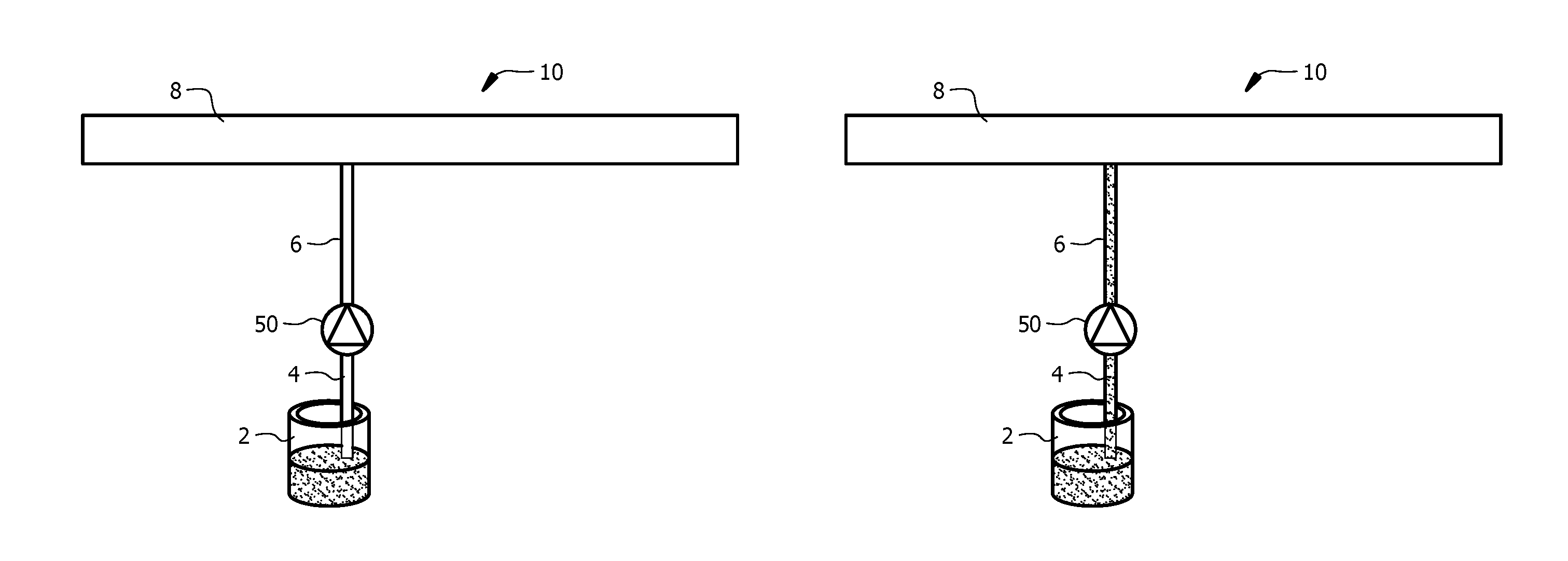
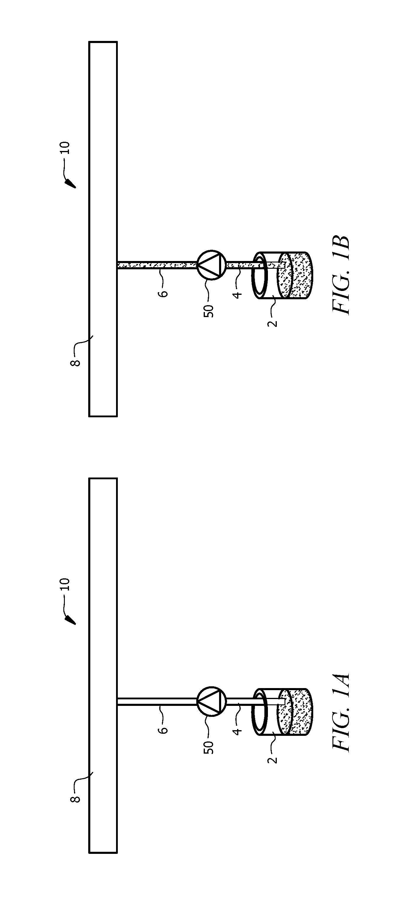
[0011] FIG. 1A depicts a schematic of a metering pump system.
[0012] FIG. 1B depicts a schematic of the metering pump system of FIG. 1 in a primed configuration.
[0013] FIG. 2 depicts a top perspective view of a metering pump of the metering pump system of FIG. 1A.
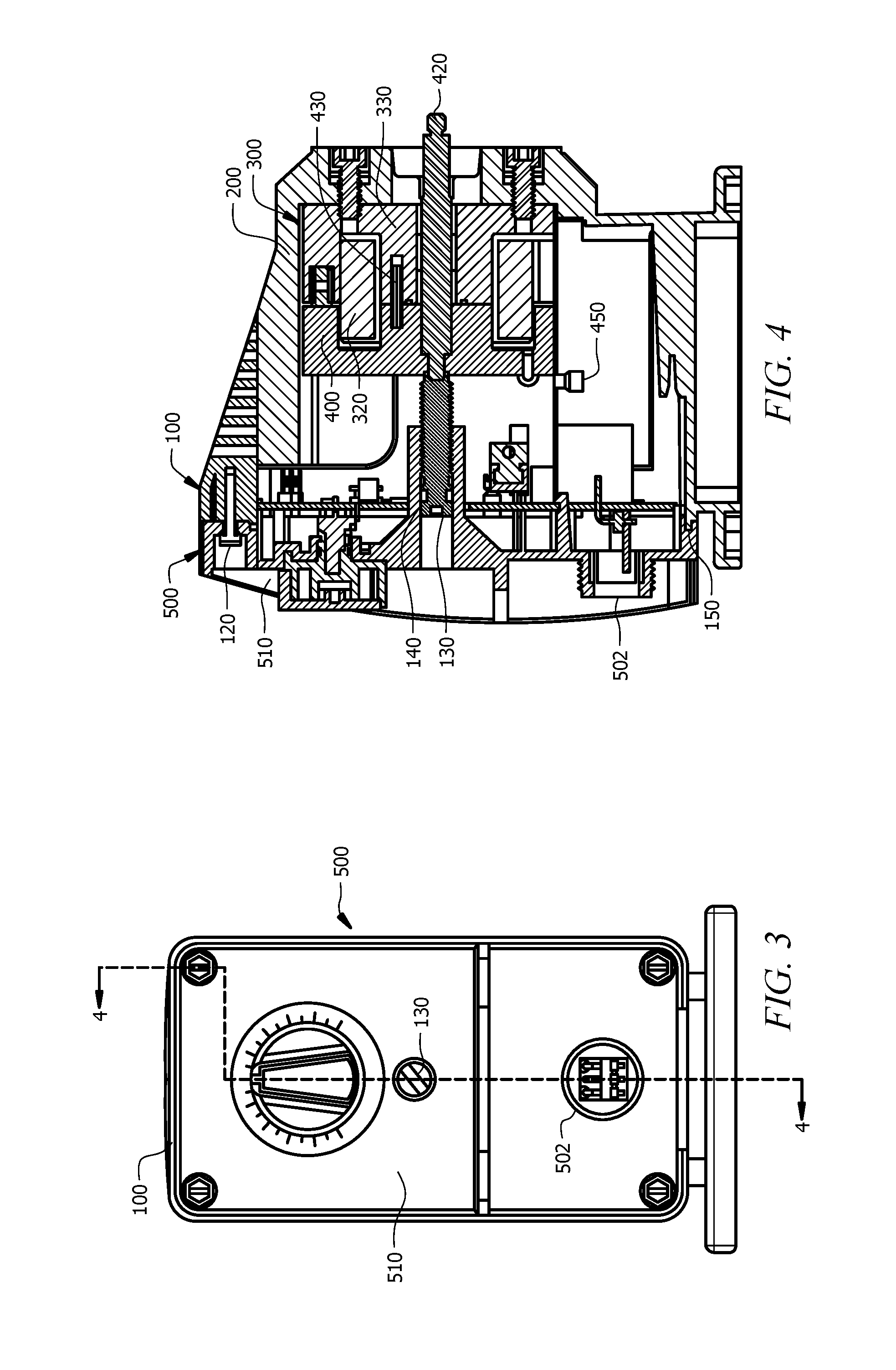
[0014] FIG. 3 depicts a front view of the metering pump of FIG. 2.
[0015] FIG. 4 depicts a cross-sectional view of the metering pump of FIG. 2 taken along line 4-4 of FIG. 3.
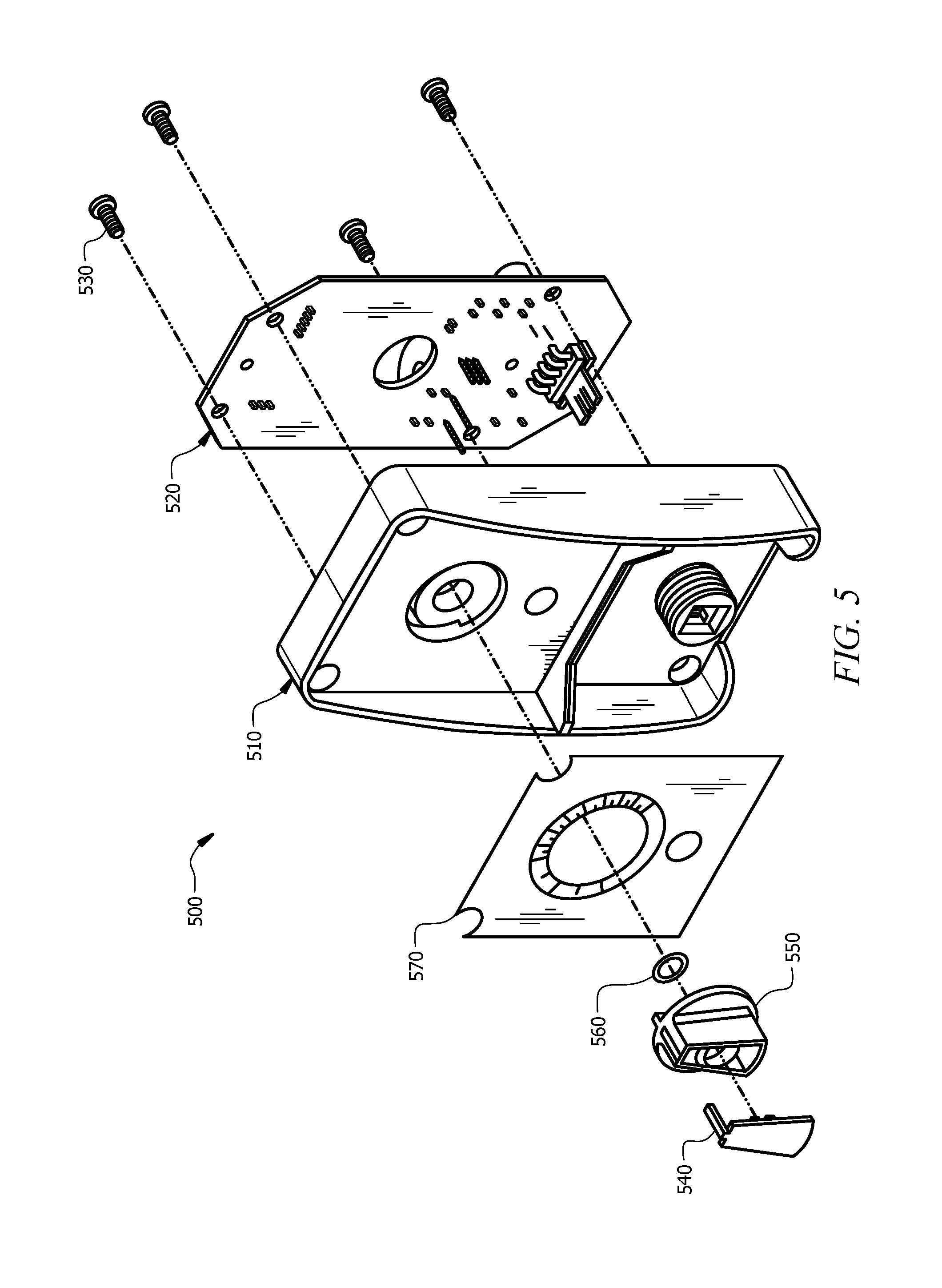
[0016] FIG. 5 depicts an exploded view of a control panel assembly of the metering pump of FIG. 2.
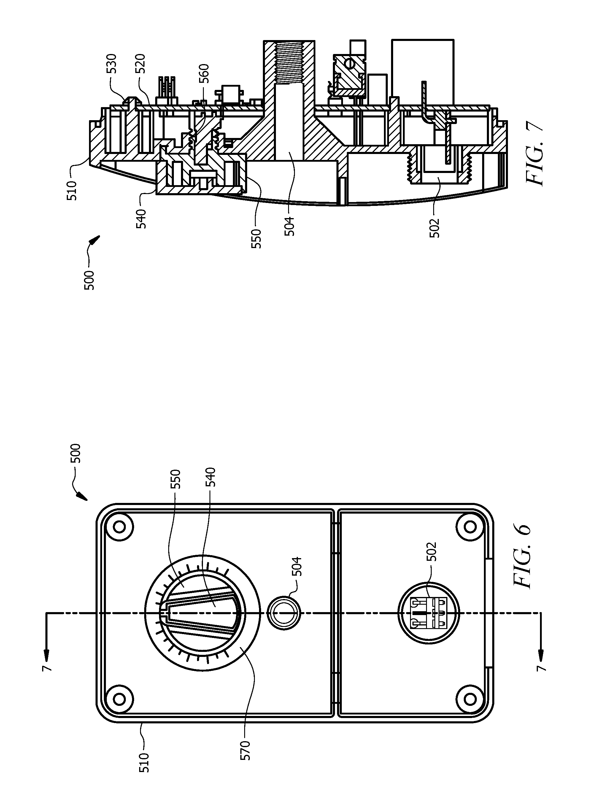
[0017] FIG. 6 depicts a front view of the control panel assembly of FIG. 5.
[0018] FIG. 7 depicts a cross-sectional view of the control panel assembly of FIG. 5 taken along line 7-7 of FIG. 6.
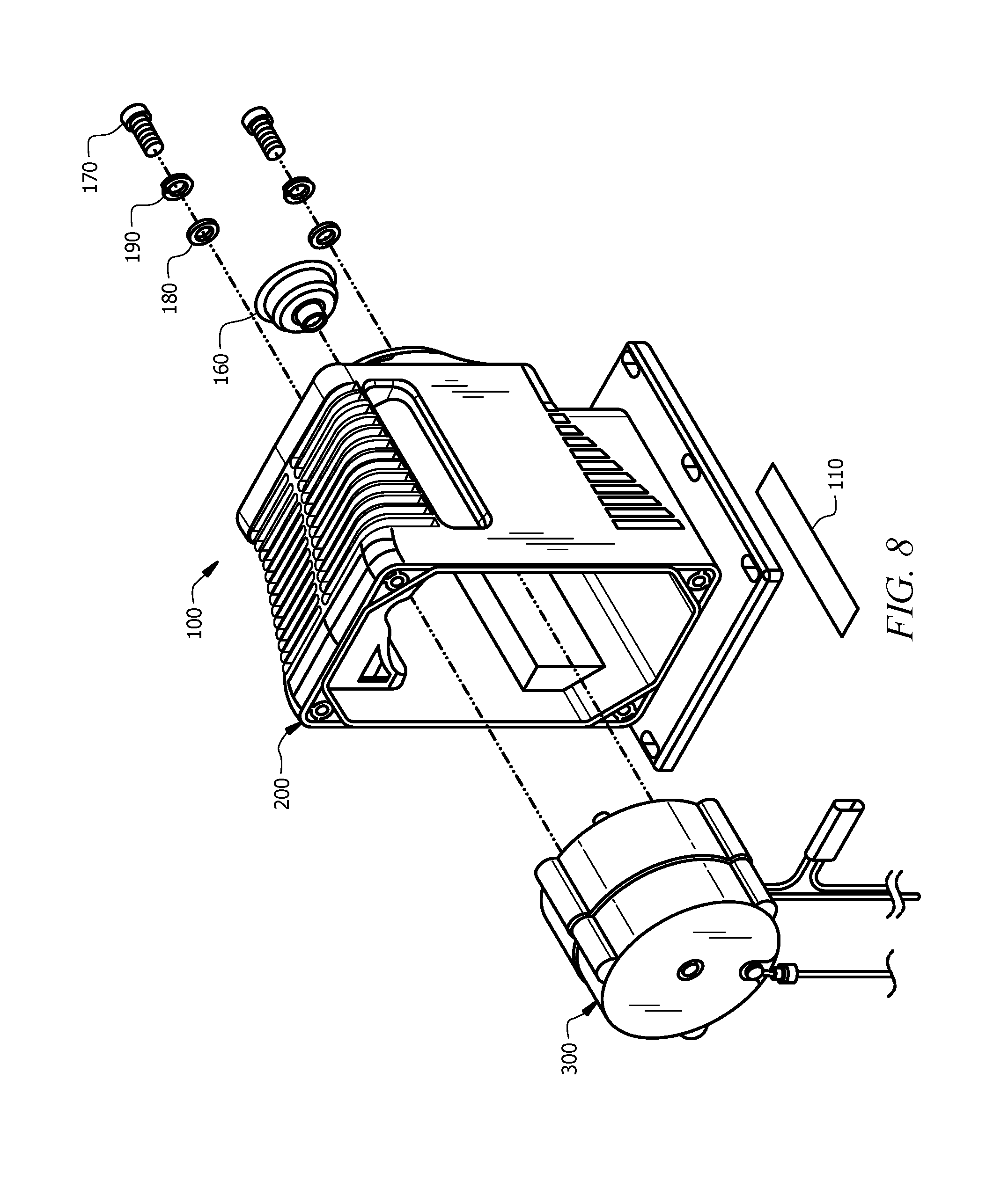
[0019] FIG. 8 depicts an exploded view of a housing assembly of the metering pump of FIG. 2, with an electronic power unit (EPU) assembly removed.
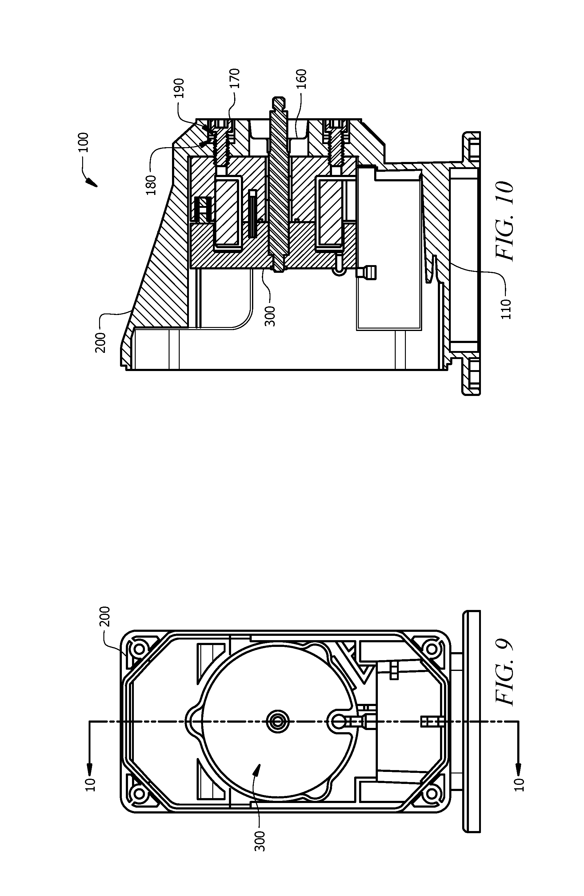
[0020] FIG. 9 depicts a front view of the housing assembly of FIG. 8, with the EPU assembly assembled with the housing assembly.
[0021] FIG. 10 depicts a cross-sectional view of the housing assembly of FIG. 8 taken along line 10-10 of FIG. 9, with the EPU assembly assembled with the housing assembly.
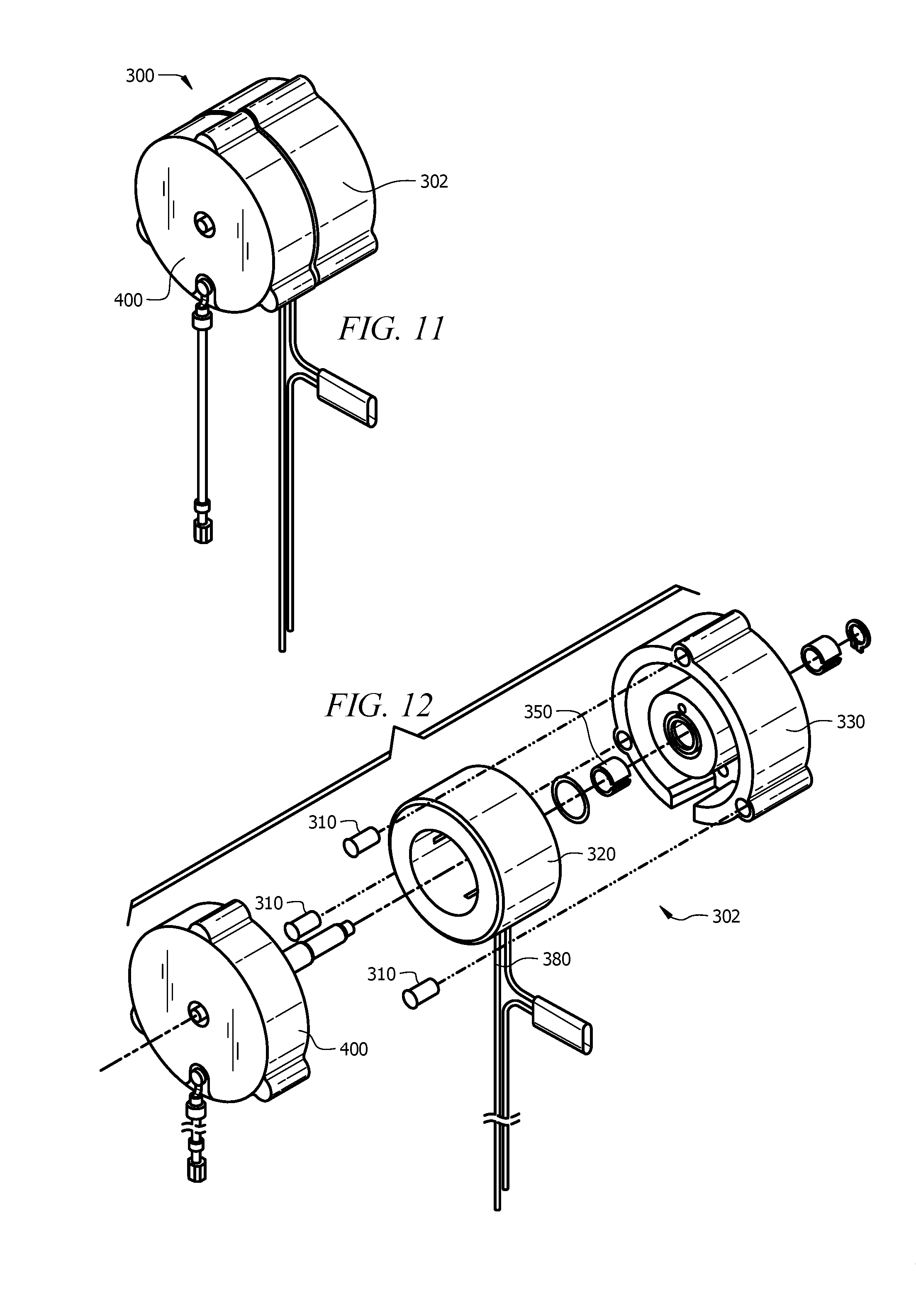
[0022] FIG. 11 depicts a top perspective view of the EPU assembly of FIG. 8.
[0023] FIG. 12 depicts an exploded view of a solenoid assembly of the EPU assembly of FIG. 8, with a clapper assembly removed.
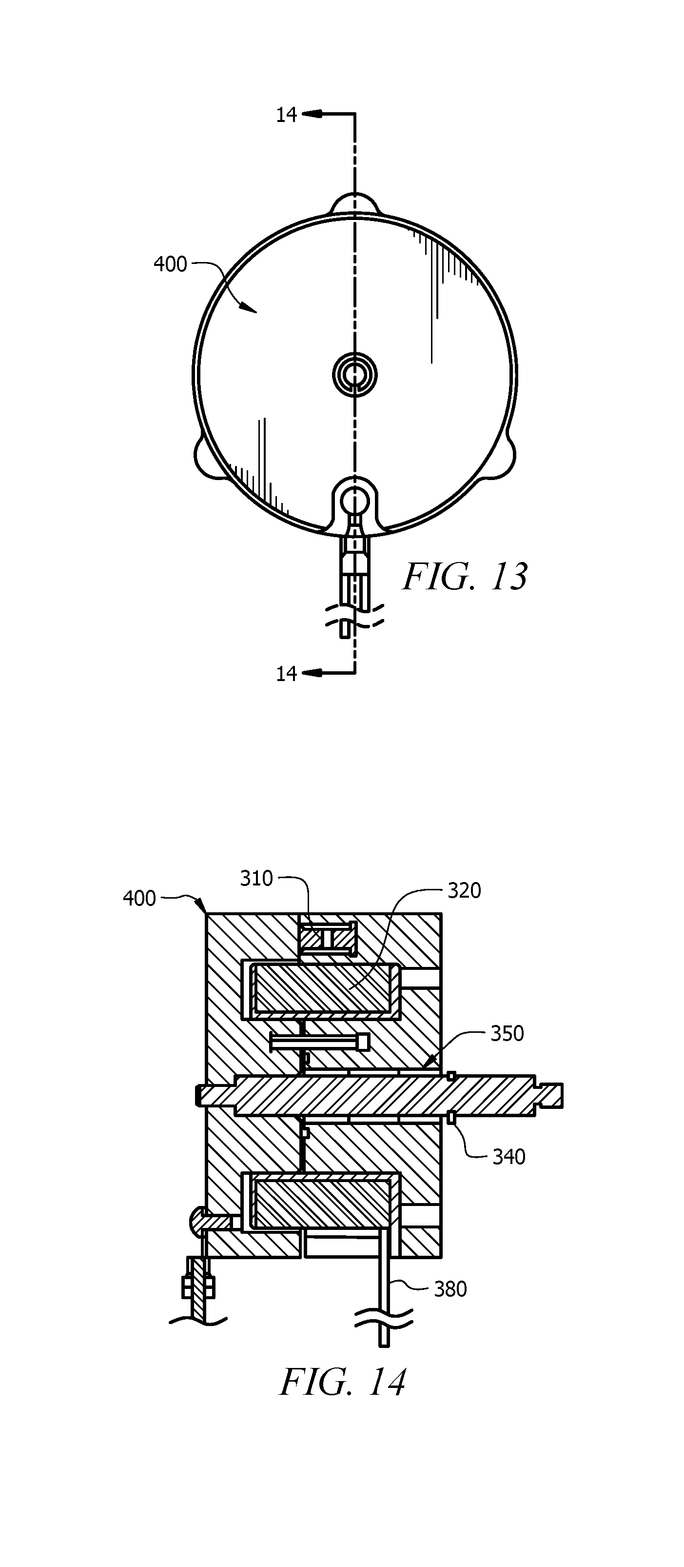
[0024] FIG. 13 depicts a front view of the EPU assembly of FIG. 8.
[0025] FIG. 14 depicts a cross-sectional view of the EPU assembly of FIG. 8 taken along line 14-14 of FIG. 13.
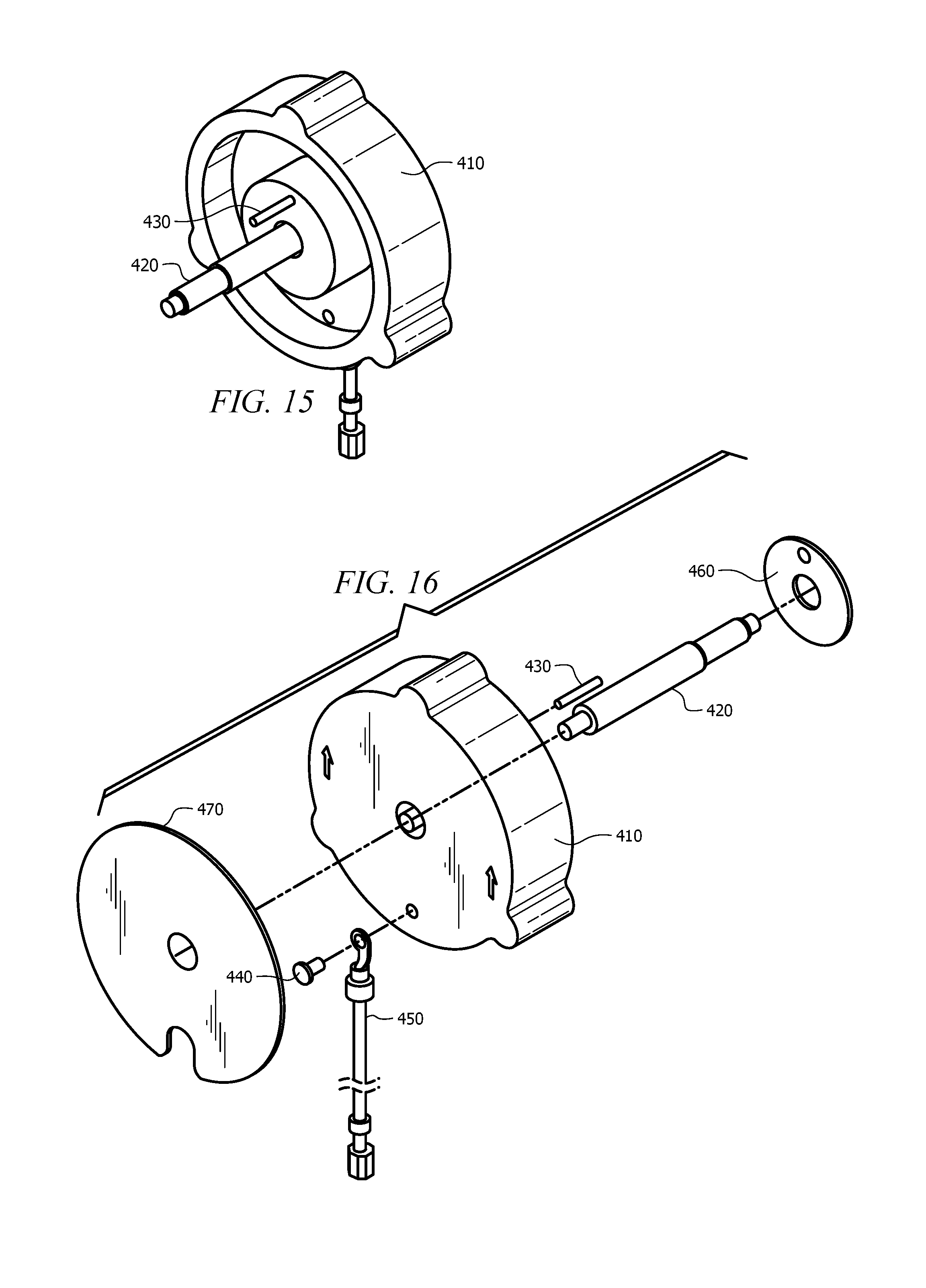
[0026] FIG. 15 depicts a rear perspective view of the clapper assembly FIG. 12.
[0027] FIG. 16 depicts a front exploded view of the clapper assembly of FIG. 15.
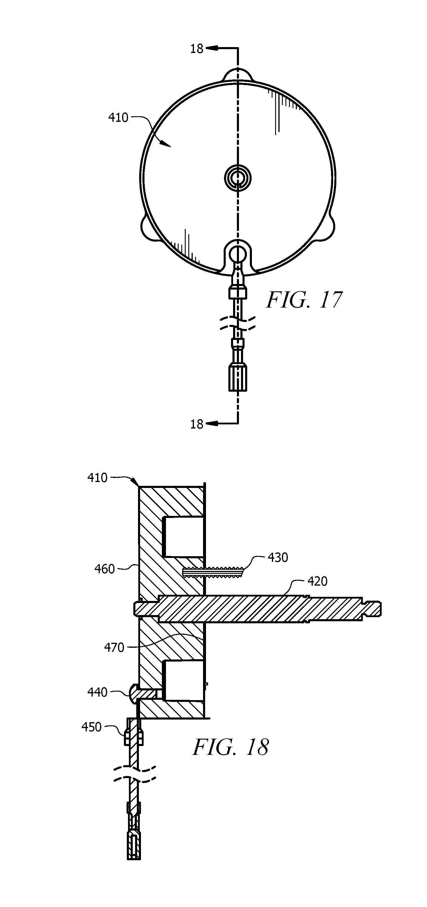
[0028] FIG. 17 depicts a front view of the clapper assembly of FIG. 15.
[0029] FIG. 18 depicts a cross-sectional view of the clapper assembly of FIG. 15 taken along line 18-18 of FIG. 17.
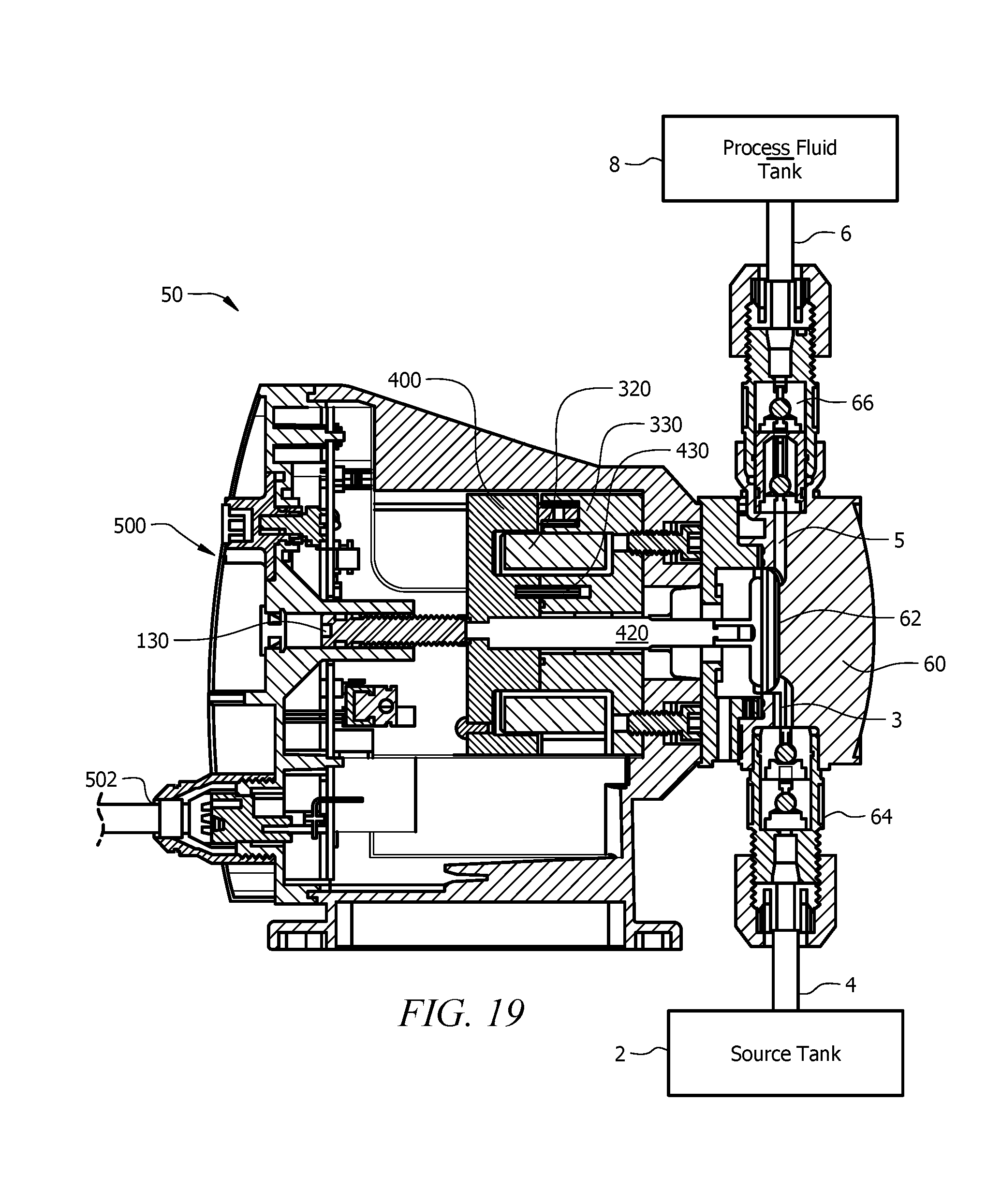
[0030] FIG. 19 depicts a cross-sectional view of the metering pump system of FIG. 1A.
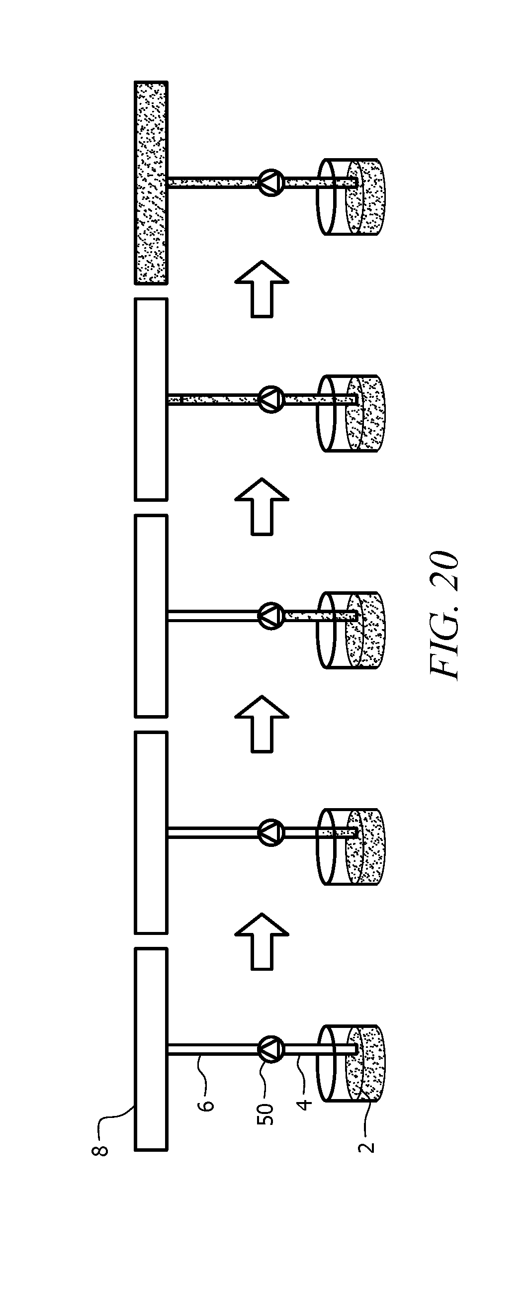
[0031] FIG. 20 depicts a schematic of a priming sequence of the metering pump system of FIG. 1A.
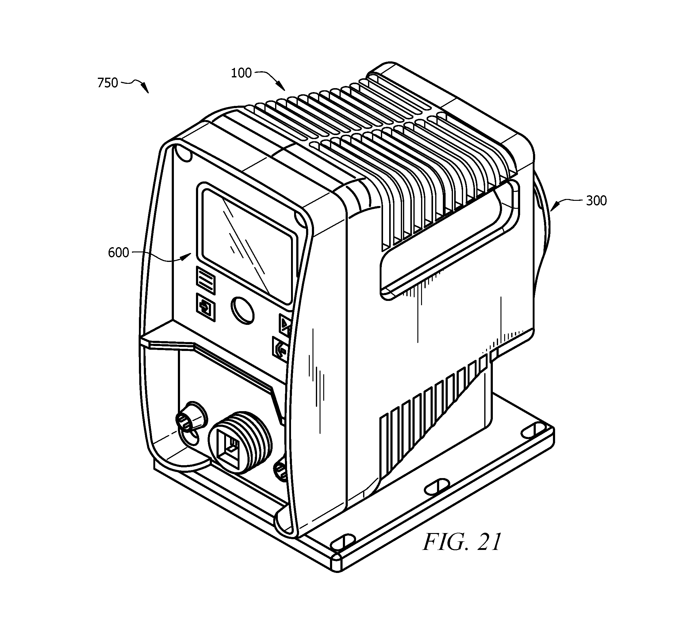
[0032] FIG. 21 depicts a top perspective view of another metering pump that can be incorporated with the metering pump system of FIG. 1A.
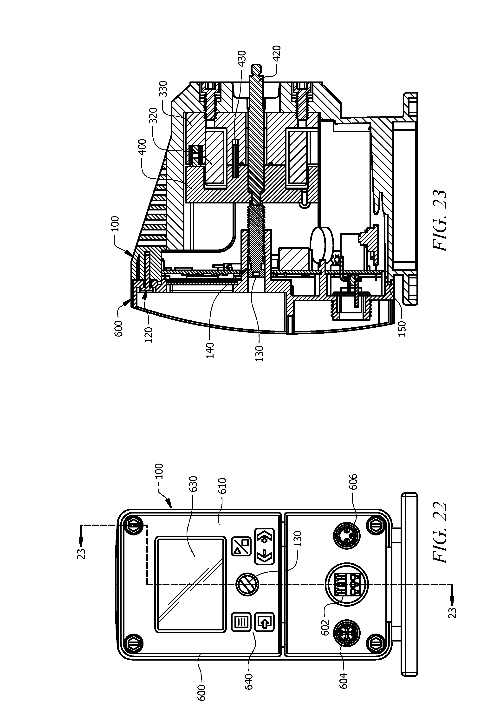
[0033] FIG. 22 depicts a front view of the metering pump of FIG. 21.
[0034] FIG. 23 depicts a cross-sectional view of the metering pump of FIG. 21 taken along line 23-23 of FIG. 22.
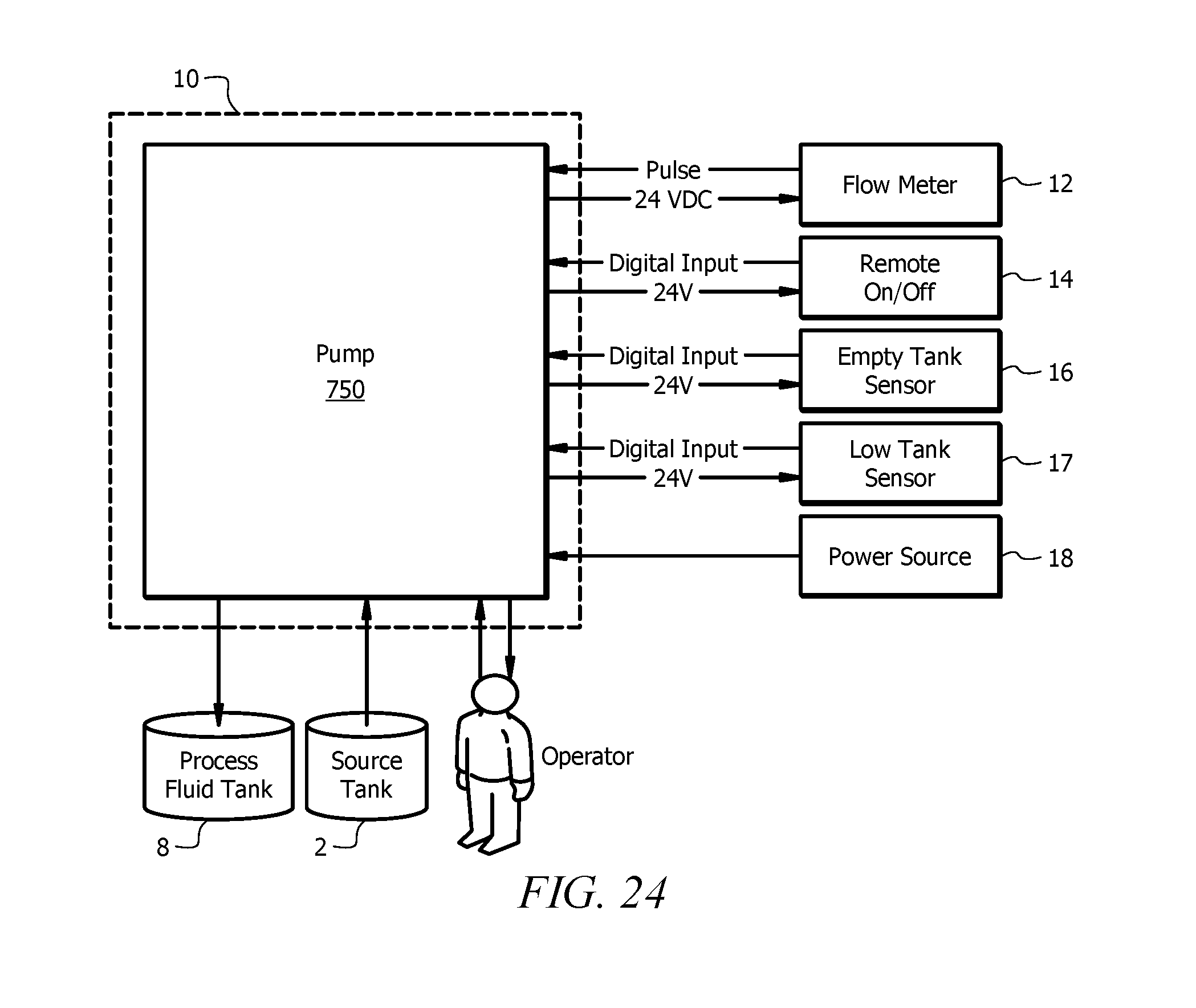
[0035] FIG. 24 depicts a schematic of an input-output configuration of the metering pump of FIG. 21.
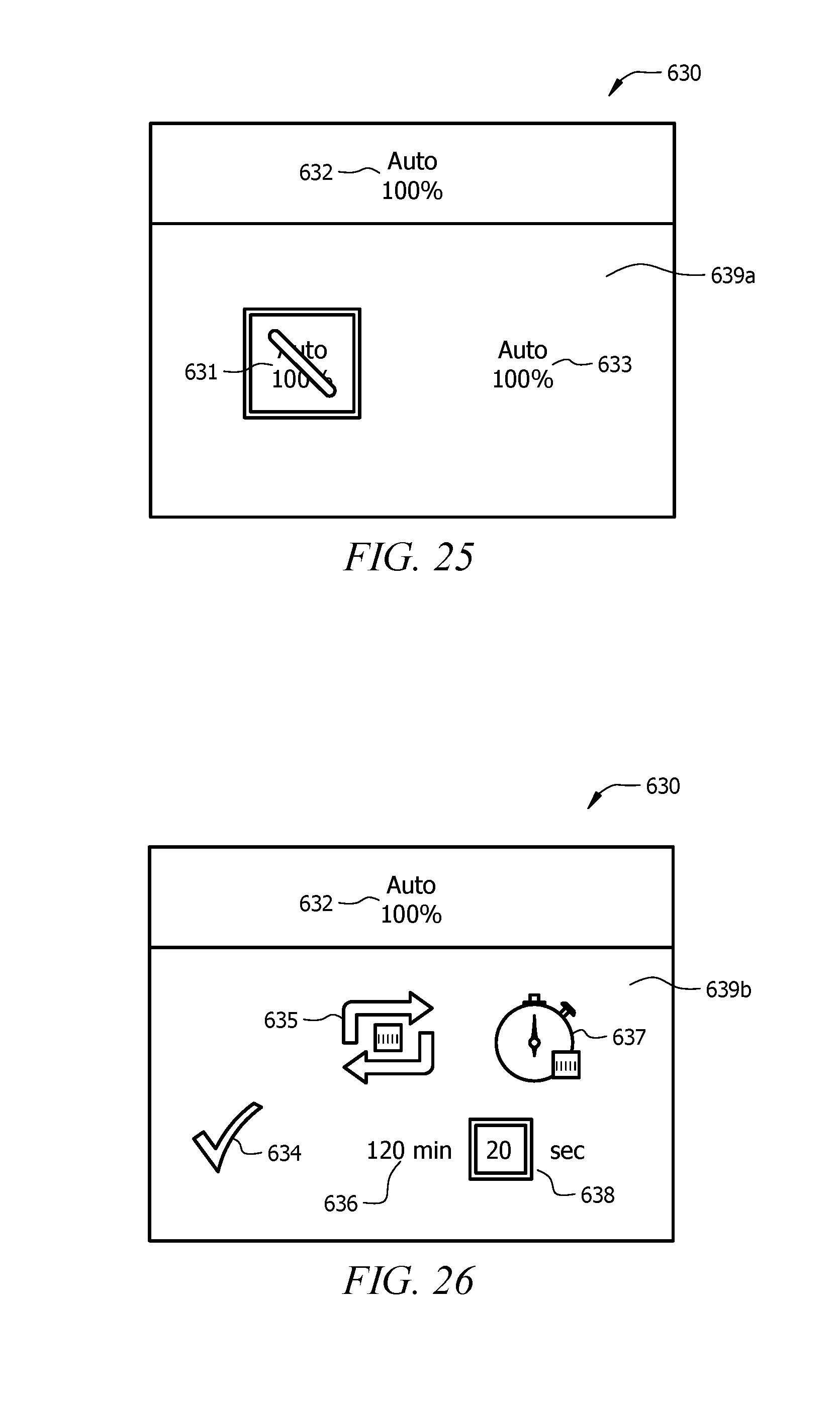
[0036] FIG. 25 depicts a schematic of a menu screen of the metering pump of FIG. 21.
[0037] FIG. 26 depicts a schematic of an automatic priming sequence screen of the metering pump of FIG. 21.
[0038] FIG. 27 depicts a schematic of an automatic priming sequence of the metering pump of FIG. 21.
DETAILED DESCRIPTION OF THE INVENTION
[0039] Referring now to FIG. 1A, an exemplary system using a metering pump is described. Metering pump system (10) for pumping a specified volume of liquid in a specified time includes a storage tank (2), a metering pump (50), and a process fluid tank (8). The metering pump (50) is fluidly coupled with the storage tank (2) by suction tubing (4), and the metering pump (50) is fluidly coupled with the process fluid tank (8) by injection tubing (6). Accordingly, the metering pump (50) can be operated to pump fluid from the storage tank (2) to the process fluid tank (8), as shown in FIG. 1B, in a specified time at a desired flow rate. The initial priming sequence of the pump (50) is the process of filling the tubing (4, 6) with fluid to a primed condition shown in FIG. 1B. Typically, this process takes several pumping cycles to fill the tubing (4, 6) adequately prior to being able to inject fluid into the process fluid tank (8). Although any type of metering pump can be incorporated into the metering pump system (10) to pump any type of fluid (i.e., chemicals, solutions, water, etc.), a diaphragm metering pump will be discussed in more detail below.
[0040] I. An Embodiment of a Diaphragm Metering Pump
[0041] An embodiment of a diaphragm metering pump (50) is shown in FIGS. 2-4. In the illustrated embodiment, the metering pump (50) comprises a control panel assembly (500) coupled to an electronic power unit (EPU) assembly (300) positioned within a housing (100). Each of these components will be described in more detail below.
[0042] As best seen in FIGS. 5-7, the control panel assembly (500) comprises a printed circuit board (PCB) assembly (520) to selectively control actuation of the pump (50). The PCB assembly (520) is coupled to rear surface of a control panel (510) by fasteners (530). A pointer (540), a speed control knob (550), a nameplate (570), and a power input (502) are positioned on a front surface of the control panel (510). The nameplate (570) in the illustrated embodiment displays adjustable speed settings for the pump (50). The pointer (540) and speed control knob (550) are then positioned over the nameplate (570) and coupled to the PCB assembly (520) through the control panel (510) with O-ring (560). Accordingly, a user can turn the speed control knob (550) to adjust the speed of the pump (50). The pointer (540) is configured to turn with the speed control knob (550) to indicate the selected speed setting on the nameplate (570). Still other suitable configurations for adjusting the speed of the pump (50) will be apparent to one with ordinary skill in the art in view of the teachings herein. An opening (504) is also defined by the control panel assembly (500) to allow a user to adjust the stroke length of the pump (50), which will be discussed in more detail below. A power source can be connected with the power input (502) of the control panel assembly (500) to provide power to the control panel assembly (500) and/or the EPU assembly (300). In some instances, the pump (50) is battery operated such that the power input (502) is merely optional. Other suitable configurations for the control panel assembly (500) will be apparent to one with ordinary skill in the art in view of the teachings herein.
[0043] The housing of the pump (50), as shown in FIGS. 4 and 8-10, comprises a cover (200) for housing the EPU assembly (300) and is coupled to a rear surface of the control panel assembly (500) by fasteners (120). A stroke length adjustment screw (130) is positioned within the opening (504) of the control panel assembly (500) such that threads of the screw (130) correspond to the threads of the opening (504). A user can thereby insert a tool, such as a screwdriver, through the opening (504) to turn the screw (130) relative to the control panel assembly (500) to adjust the stroke length of the pump (50). Still other suitable configurations for adjusting the stroke length will be apparent to one with ordinary skill in the art in view of the teachings herein. The EPU assembly (300) is coupled with the cover (200) with fasteners (170, 180, 190) and sealed with O-rings (140, 150) and a seal (160) at the rear surface of the cover (200). A label (110) can optionally be adhered or coupled to a surface of the housing (100) to provide identifying information for the pump (50). Other suitable configurations for the housing (100) will be apparent to one with ordinary skill in the art in view of the teachings herein.
[0044] Referring to FIGS. 11-14, the EPU assembly (300) comprises a clapper assembly (400) coupled with a solenoid assembly (302). The solenoid assembly (302) comprises a coil (320) inserted within a pole piece (330). The coil (320) is coupled to the PCB assembly (520) of the control panel assembly (500) by wiring (380). The PCB assembly (520) can thereby send pulses of electrical energy to the coil (320) to selectively activate the solenoid assembly (302). For instance, when the coil (320) is activated, it produces a magnetic field that is directed to the clapper assembly (400) by the pole piece (330). Accordingly, the solenoid assembly (302) is selectively activated to reciprocate the clapper assembly (400) forward and backward relative to the solenoid assembly (302). In the illustrated embodiment, at least one spring and pad assembly (310) is positioned between the clapper assembly (400) and the solenoid assembly (302) to relieve the impact of the clapper assembly (400) against the solenoid assembly (302). A bushing (350) is also positioned around a shaft (420) of the clapper assembly (400) to reduce friction as the clapper assembly (400) translates relative to the solenoid assembly (302).
[0045] The clapper assembly (400), as best seen in FIGS. 15-18, comprises a clapper (410) with a shaft (420) and a spring pin (430) extending outward from a rear surface of the clapper (410). The shaft (420) is configured to extend from the housing (100), through an opening of the solenoid assembly (302) and seal (160) of the housing (100). The shaft (420) can thereby be reciprocated relative to the solenoid assembly (302) to actuate a diaphragm (62) of the pump (50). A ground wire assembly (450) is coupled to the clapper (410) by a fastener (440). A first shim (460) is coupled to a front surface of the clapper (410) and a second shim (470) is coupled to a rear surface of the clapper (410) to reduce friction and/or wear of the clapper (410). Still other suitable configurations for the EPU assembly (300) will be apparent to one with ordinary skill in the art in view of the teachings herein.
[0046] II. Operation of the Diaphragm Metering Pump
[0047] As discussed above, the metering pump (50) can be used to transfer fluid from a source tank (2) to a process fluid tank (8) for treatment. Referring to FIG. 19, the diaphragm metering pump (50) generally draws in the fluid from the source tank (2) to an inlet (3) at a first pressure, and discharges the fluid through an outlet (5) at a second pressure. During a suction stroke, the pump (50) creates a negative pressure scenario that lifts the fluid from the source tank (2) into the suction tube (4) toward the inlet (3), or suction end, of the pump (50). During the discharge stroke, the pump (50) creates a positive pressure differential to move the fluid towards the outlet (5), or discharge end, of the pump (50).
[0048] In the illustrated embodiment, the pump (50) is coupled to a pump chamber (60) and a diaphragm (62) is positioned between the pump (50) and the pump chamber (60) such that the diaphragm (62) is aligned with the shaft (420) of the clapper assembly (400). The shaft (420) thereby actuates the diaphragm (62) to create a reciprocating motion that leads to pressure changes within the pump chamber (60). The pump chamber (60) includes an inlet (3) and an outlet (5). The inlet (3) comprises a first check valve (64) and is fluidly coupled to the source tank (2) through suction tubing (4). The outlet (5) comprises a second check valve (66) and is fluidly coupled to the process fluid tank (8). The term "check valve" should be understood to mean a valve having a checking element configured to allow fluid to pass in one direction and arrest fluid flow in an opposing direction. Accordingly, the first check valve (64) allows fluid to enter the pump chamber (62) from the fluid source (2) during a suction stroke and prevents fluid from exiting through the inlet (3) during a pressure stroke. The second check valve (66) allows fluid to flow from the pump chamber (60) toward the process fluid tank (8) during a pressure stroke and prevents fluid from being ingested into the pump chamber (60) through outlet (5) during a suction stroke.
[0049] The initial priming sequence of the pump (50) is the process of filling the tubing (4, 6) with fluid such that the pumping system (10) is in an active state prepared to actively inject fluid into the fluid process tank (8). Typically, this priming process takes several pumping cycles of the pump (50) to fill the tubing (4, 6) adequately prior to being able to inject fluid into the process fluid tank (8), as shown in FIG. 20.
[0050] In some instances, the pump (50) may be subject to a loss of prime condition where a portion or all of the tubing (4, 6) is not filled with liquid. During a loss of prime condition, the pressure vacuum in the tubing (4, 6) may be lost and the fluid may reverse flow from the tubing (4, 6) back into the source tank (2). This may particularly occur in low duty cycle pumping applications or if the pump (50) is turned off for an extended amount of time. When prime is lost in the system (10), the system (10) can be re-primed by actuating the pump (50) to return fluid to an adequate level. However, this re-priming may require manual intervention, may be time consuming, and may result in under treating the process fluid.
[0051] III. Automatic Priming of a Metering Pump
[0052] Because it may be desirable to maintain fluid in the tubing (4, 6) of the pumping system (10) such that the pump (50) is in a primed condition, a recurring automatic priming function is provided by running the pump (50) for a short duration and periodically thereafter. This may assist in applications where the pump (50) is controlled by a power relay. The pump (50) may then return to its set operating mode until the time specified in the recurrence has elapsed. The pump (50) may then run again for the set duration and again return to its set operating mode. A user can enable and adjust the automatic priming functionality by setting a recurrence schedule and a duration period that is applicable to the characteristics of each pumping system (10). This can eliminate the need for manual adjustments of the pump (50) to alleviate loss of prime, which is beneficial because typically the system (10) has already been in a prime loss state prior to manual intervention. This automatic priming sequence is also more efficient because there is no time delay in waiting for the pump (50) to regain prime and there is no under treatment of the process fluid.
[0053] Such an automatic priming sequence can also be incorporated on a metering pump, such as a metering pump (750) shown in FIGS. 21-23. The metering pump (750) is similar to the metering pump (50) described above, except that the metering pump (750) comprises a digital control panel assembly (600). As best seen in FIG. 22, the digital control panel assembly (600) comprises an LCD screen (630) and a keypad (640) positioned on a front surface of the control panel (610). The LCD screen (630) can display the selected settings for the pump (750) to a user. The LCD screen (630) can be about a 2.4-inch color display, but other suitable configurations can be used. The keypad (640) can be used to enable and/or adjust the automatic priming sequence settings. The digital control assembly (600) further comprises a power input (602), an external control input (604), and a source tank input (606). The power input (602) can be used to couple a power source with the pump (750). The external control input (604) can be used to couple an external control with the pump (750) to remotely start/stop and/or pulse the metering pump (750). The source tank input (606) can be used to couple the pump (750) with a source tank sensor to detect a low level and/or an empty source tank (2). Accordingly, the pump (750) can automatically stop actuating if there is an insufficient amount of fluid in the source tank (2).
[0054] For instance, an input-output schematic of the pump (750) is shown in FIG. 24. A power source (18) can be coupled with the power input (602) of the pump (750) to supply power to the control panel assembly (600) and/or the EPU assembly (350). The power source (18) can supply between about 85 and about 265 Volts. Of course, other suitable power supply ranges and configurations for the pump (750) can be used. The control panel assembly (600) can then selectively actuate the EPU assembly (300) to control the pump (750). The pump (750) is thereby operable to pump fluid from the source tank (2) to the process fluid tank (8).
[0055] A user can input and/or adjust desired settings for the pump (750) through the keypad (640) of the control panel assembly (600). The screen (630) of the control panel assembly (600) can then display the selected settings of the pump (750) to the user. An external control (14) can be coupled with the external control input (604) of the pump (750) to provide a remote start/stop and/or pulse control of the pump (750). An empty tank sensor (16) and/or a lower level tank sensor (17) can be coupled with the source tank input (606) of the pump (750) to detect a low level and/or an empty source tank (2), which can automatically stop actuating the pump (750) if there is an insufficient amount of fluid in the source tank (2). A flow meter (12) can also be coupled with the pump (750) to measure the flow rate of the pump (750). In some instances, the pump (750) provides about a 24V output to the flow meter (12), the external control (14), the sensors (16, 17), and/or any combination thereof. Other suitable configurations for operating the pump (750) will be apparent to one with ordinary skill in the art in view of the teachings herein.
[0056] The automatic priming sequence can be enabled and/or configured on the metering pump (750). For instance, FIGS. 25-26 show the LCD screen (630) of the control panel assembly (600) with an embodiment of a menu screen (639a) and an automatic priming sequence screen (639b) for illustrative purposes. The menu screen (639a) of FIG. 25 displays an automatic priming system icon (631) that can be adjusted to enable and/or disable the automatic priming sequence. In the illustrated embodiment, the automatic priming sequence is disabled by default. The menu screen (639a) further comprises a pump capacity icon (633) that can be adjusted to select a desired operating pump capacity. In the illustrated embodiment, the pump capacity is set to a maximum pump capacity at 100%. The pump (750) can run at any desired priming capacity, such as at a maximum capacity, an elevated capacity higher than its normal operating capacity, its normal operating capacity, a lower capacity than its normal operating capacity, or any combination thereof. This pump capacity setting is confirmed in the pump capacity setting display (632). A user can adjust the pump settings using the keypad (640), which may include push button controls to start and/or stop the pump (750), select a desired speed for the pump (750), display a settings menu for the pump (750), and/or an enter button to select the settings for the pump (750). For instance, the pump speed can be adjusted from between about 0 and about 220 strokes per minute, and the performance range of the pump can be adjusted to pump between about 0 and about 2.5 gallons per hour at between about 0 and about 250 psi. The LCD screen (630) can further display alert and/or alarm notifications, the flow rate, the stroke speed, and/or the percent capacity of the pump (750) to the user. The menu can provide options for a user to select a manual mode, a pulse mode, calibration, units of measure, totalizer, and/or automated priming of the pump (750). Of course, other suitable configurations for adjusting the pump settings can be used.
[0057] An embodiment of the LCD screen (630) for displaying and/or adjusting the automatic priming settings is shown in FIG. 26. In the illustrated embodiment, the selected recurrence schedule is displayed with the recurrence schedule icon (635) to show that the recurrence timer (636) is set to 120 minutes. The control panel assembly (600) can be used to adjust this recurrence timer (636) to any desirable amount of time. In the illustrated embodiment, the duration period is displayed with the duration period icon (637) to show that the duration period (638) is set to 20 seconds. The control panel assembly (600) can also be used to adjust this duration period to any desirable amount of time. These settings are displayed as being confirmed by the digital control panel assembly (600) by confirmation icon (634). Accordingly, with these selected automatic priming settings, the digital control panel assembly (600) can activate the pump (750) to run in a priming configuration at maximum capacity for 20 seconds every 120 minutes to maintain the pump (750) in a primed condition. This feature may run the pump (750) as long as the pump (750) is in the running state, even if the pump (750) is in manual mode with the stroke rate set to 0%, or in external pulse mode with no incoming pulses. Other suitable configurations for adjusting these settings will be apparent to one with ordinary skill in the art in view of the teachings herein.
[0058] Referring to FIG. 27, such an automatic priming sequence comprises powering the pump on (710) and running the pump (750) for a selected duration period (712). For instance, a user can select a desired amount of time to run the pump (750) and/or select a desired capacity at which to run the pump (750) to drive fluid into the tubing (4, 6) of the pumping system (10). The pump (750) can run at any desired priming capacity during this duration period, such as at a maximum capacity, an elevated capacity higher than its normal operating capacity, its normal operating capacity, a lower capacity than its normal operating capacity, or any combination thereof. The amount of time for the duration period and/or the pump capacity can be adjustable. In some instances, the stroke speed and/or the stroke length can be adjusted for a desired priming configuration. After the duration period is reached, the pump (750) can be set to its configured operating mode (714) for normal operation of the pump (750). When the amount of time set for the desired recurrence schedule is reached (716), the system (10) can automatically repeat running the pump (750) for the selected duration period (712) at the selected pump capacity. The recurrence schedule can also be adjustable. This initiation of an automatic priming system can easily and more efficiently maintain the pump in a primed configuration. Such control of the pump (750) can be provided by the control panel assembly (600). Other suitable configurations for automatically initiating the priming sequence of the pump (750) will be apparent to one with ordinary skill in the art in view of the teachings herein.
[0059] For instance, in some versions, additional fluid may be pumped into the process fluid tank (8) after running the automated priming sequence if there was already fluid in the tubing (4, 6). As an example, with the pump (750) set to run at maximum capacity for 20 seconds every 120 minutes, the pump (750) may pump about an additional 1.1% of the maximum capacity of the pump. If such a small addition is not acceptable to a user, the user can select a reduced pump setpoint using the following equation.
Setpoint = Desired Flow Rate - Max Capacity * Recurrence 60 * Duration 3600 ##EQU00001##
[0060] In some versions, the pump system (10) can be used to detect a loss of prime condition to activate the automatic priming sequence in addition to or instead of the recurrence timer. An example for detecting a loss of prime condition is described in U.S. patent application Ser. No. TBD, entitled Solenoid Current Monitoring Method for Leak Detection and Vapor Lock, filed on TBD, the disclosure of which is incorporated by reference herein.
[0061] In some versions, the pump system (10) can be used to detect that the system (10) is primed to automatically end the priming sequence in addition to or instead of the duration period timer. For instance, a sensor may be placed in the tubing (4, 6) to detect fluid in the tubing (4,6) to thereby indicate that the pump (750) is primed.
[0062] Although the present invention and its advantages have been described in detail, it should be understood that various changes, substitutions and alterations can be made herein without departing from the spirit and scope of the invention as defined by the appended claims. Moreover, the scope of the present application is not intended to be limited to the particular embodiments of the process, machine, manufacture, composition of matter, means, methods and steps described in the specification. As one of ordinary skill in the art will readily appreciate from the disclosure of the present invention, processes, machines, manufacture, compositions of matter, means, methods, or steps, presently existing or later to be developed that perform substantially the same function or achieve substantially the same result as the corresponding embodiments described herein may be utilized according to the present invention. Accordingly, the appended claims are intended to include within their scope such processes, machines, manufacture, compositions of matter, means, methods, or steps.
* * * * *
D00000
D00001
D00002
D00003
D00004
D00005
D00006
D00007
D00008
D00009
D00010
D00011
D00012
D00013
D00014
D00015
D00016
D00017
D00018


XML
uspto.report is an independent third-party trademark research tool that is not affiliated, endorsed, or sponsored by the United States Patent and Trademark Office (USPTO) or any other governmental organization. The information provided by uspto.report is based on publicly available data at the time of writing and is intended for informational purposes only.
While we strive to provide accurate and up-to-date information, we do not guarantee the accuracy, completeness, reliability, or suitability of the information displayed on this site. The use of this site is at your own risk. Any reliance you place on such information is therefore strictly at your own risk.
All official trademark data, including owner information, should be verified by visiting the official USPTO website at www.uspto.gov. This site is not intended to replace professional legal advice and should not be used as a substitute for consulting with a legal professional who is knowledgeable about trademark law.