Screw Pump
INOUE; Masashi ; et al.
U.S. patent application number 16/123040 was filed with the patent office on 2019-03-14 for screw pump. The applicant listed for this patent is DENSO CORPORATION. Invention is credited to Yuuji HIDAKA, Masashi INOUE, Masatoshi TAKAGI, Yasuhiro TAKEUCHI.
| Application Number | 20190078566 16/123040 |
| Document ID | / |
| Family ID | 65630772 |
| Filed Date | 2019-03-14 |


| United States Patent Application | 20190078566 |
| Kind Code | A1 |
| INOUE; Masashi ; et al. | March 14, 2019 |
SCREW PUMP
Abstract
A screw pump has a male screw accommodation hole and a female screw accommodation hole formed in a pump housing. A male screw member and a female screw member are respectively accommodated in the male screw accommodation hole and the female screw accommodation hole. A male-side clearance is formed in a radial direction between the male screw member and the male screw accommodation hole and a female-side clearance is formed in the radial direction between the female screw member and the female screw accommodation hole. The female-side clearance is made to be larger than the male-side clearance, so that the female screw member can easily move in a direction away from the male screw member to the female-side clearance when any extraneous material is going to be wedged between the male screw member and the female screw member, to thereby prevent a locked condition of the screw members.
| Inventors: | INOUE; Masashi; (Nisshin-city, JP) ; TAKEUCHI; Yasuhiro; (Nisshin-city, JP) ; HIDAKA; Yuuji; (Kariya-city, JP) ; TAKAGI; Masatoshi; (Kariya-city, JP) | ||||||||||
| Applicant: |
|
||||||||||
|---|---|---|---|---|---|---|---|---|---|---|---|
| Family ID: | 65630772 | ||||||||||
| Appl. No.: | 16/123040 | ||||||||||
| Filed: | September 6, 2018 |
| Current U.S. Class: | 1/1 |
| Current CPC Class: | F04C 13/005 20130101; F04C 2280/02 20130101; F04C 2/16 20130101; F04C 14/28 20130101; F04C 13/008 20130101 |
| International Class: | F04C 2/16 20060101 F04C002/16; F04C 13/00 20060101 F04C013/00 |
Foreign Application Data
| Date | Code | Application Number |
|---|---|---|
| Sep 11, 2017 | JP | 2017-173796 |
Claims
1. A screw pump comprising; a male screw member and a female screw member, one of which forms a driving-side screw member and the other of which forms a driven-side screw member; a driving-side convex portion of a spiral shape formed at an outer peripheral surface of the driving-side screw member, which is rotatable about a first rotational axis; and a driven-side convex portion of a spiral shape formed at an outer peripheral surface of the driven-side screw member, which is rotatable about a second rotational axis together with the driving-side screw member, wherein the driving-side screw member and the driven-side screw member are operatively engaged with each other and rotated together in order to pressurize working fluid from a suction port of a low pressure side and to pump out the working fluid from a discharge port of a high pressure side, and wherein the screw pump further comprises; (i) a pump housing; (ii) a driving-side screw accommodation hole formed in the pump housing and movably accommodating the driving-side screw member; (iii) a driven-side screw accommodation hole formed in the pump housing and movably accommodating the driven-side screw member; and (iv) a lock-prevention portion for preventing a locked condition of the driving-side screw member and the driven-side screw member, which is caused by extraneous material entering the driving-side screw accommodation hole and/or the driven-side screw accommodation hole, wherein the lock-prevention portion is formed at least in one of the following portions, (iv-a) the driving-side screw accommodation hole, (iv-b) the driven-side screw accommodation hole, and (iv-c) a screw engagement portion at which the driving-side screw member and the driven-side screw member are engaged with each other.
2. The screw pump according to claim 1, wherein a first clearance is formed in a radial direction of the driving-side screw accommodation hole between an outer periphery of the driving-side convex portion of the driving-side screw member and an inner peripheral wall of the driving-side screw accommodation hole, a second clearance is formed in a radial direction of the driven-side screw accommodation hole between an outer periphery of the driven-side convex portion of the driven-side screw member and an inner peripheral wall of the driven-side screw accommodation hole, and one of the first clearance and the second clearance is larger than the other of the first clearance and the second clearance.
3. The screw pump according to claim 2, wherein the driving-side convex portions has a first tooth width in an axial direction of the driving-side screw member, the driven-side convex portions has a second tooth width in an axial direction of the driven-side screw member, one of the tooth widths is larger than the other tooth width.
4. The screw pump according to claim 2, wherein the one of the first clearance and the second clearance, which is larger than the other, extends in a circumferential direction of the corresponding screw member from a forward-side boundary portion to a circumferential middle portion of the inner peripheral wall of the corresponding screw accommodation hole, the forward-side boundary portion is a portion formed between the inner peripheral wall of the driving-side screw accommodation hole and the inner peripheral wall of the driven-side screw accommodation hole, and the forward-side boundary portion is located at a point of a screw engagement area between the screw members on a forward side of a rotation of the corresponding screw member, the circumferential middle portion is a portion of the inner peripheral wall of the corresponding screw accommodation hole between the forward-side boundary portion and a backward-side boundary portion, and the backward-side boundary portion is another portion formed between the inner peripheral wall of the driving-side screw accommodation hole and the inner peripheral wall of the driven-side screw accommodation hole, and the backward-side boundary portion is located at a point of the screw engagement area between the screw members on a backward side of the rotation of the corresponding screw member.
5. The screw pump according to claim 2, wherein the one of the first clearance and the second clearance, which is larger than the other, extends in a circumferential direction of the corresponding screw member from a forward-side boundary portion and reduces in its size in a direction of a rotation of the corresponding screw member, and the forward-side boundary portion is a portion formed between the inner peripheral wall of the driving-side screw accommodation hole and the inner peripheral wall of the driven-side screw accommodation hole, and the forward-side boundary portion is located at a point of a screw engagement area between the screw members on a forward side of a rotation of the corresponding screw member.
6. The screw pump according to claim 1, wherein the lock-prevention portion is formed in the screw engagement portion of the driving-side screw member and/or the driven-side screw member, wherein the driving-side and the driven-side screw members are engaged with each other at the screw engagement portion.
7. The screw pump according to claim 6, wherein the driving-side screw member is made of a male screw member having a double thread screw structure, the driven-side screw member is made of a female screw member having a triple thread screw structure, and a groove of the female screw member, with which the driving-side convex portion is engaged, is recessed in a radial-inward direction of the female screw member to such an extent that a radial-outward end of the driving-side convex portion is not brought into contact with such a radial-inward recessed surface of the groove, so that the groove with the radial-inward recessed surface works as the lock-prevention portion.
8. The screw pump according to claim 1, wherein the lock-prevention portion includes a member made of material having rigidity lower than that of the pump housing.
9. The screw pump according to claim 6, wherein the driving-side screw member is composed of the male screw member having the driving-side convex portions, the driven-side screw member is composed of the female screw member having grooves, with each of which the driving-side convex portion is respectively engaged, wherein each of the grooves has a groove surface recessed in a radial-inward direction of the female screw member from a reference line, so that a radial-outward end of the driving-side convex portion is not brought into contact with a bottom end of the groove surface when the driving-side screw member and the drive-side screw member are engaged with each other.
10. The screw pump according to claim 6, wherein the driving-side screw member is composed of the male screw member having the driving-side convex portions, the driven-side screw member is composed of the female screw member having grooves, with each of which the driving-side convex portion is respectively engaged, wherein each of the grooves has a groove surface recessed in a radial-inward direction of the female screw member from a reference line in a forward-side groove area of the groove, so that a radial-outward end of the driving-side convex portion is not brought into contact with the groove surface of the forward-side groove area when the driving-side screw member and the drive-side screw member are engaged with each other.
Description
CROSS REFERENCE TO RELATED APPLICATION
[0001] This application is based on Japanese Patent Application No. 2017-173796 filed on Sep. 11, 2017, the disclosure of which is incorporated herein by reference.
FIELD OF TECHNOLOGY
[0002] The present disclosure relates to a screw pump for pressurizing and pumping out working fluid by use of rotation of screw members.
BACKGROUND
[0003] The screw pump is known in the art, for example, as disclosed in Japanese Patent Publication No. 2004-36547. In the screw pump, working fluid is pressurized and pumped out by rotation of multiple screw members. A radial gap between the screw members as well as a radial gap between the screw member and a pump housing is generally very small, for example, several ten micro-meters (.mu.m). In a case that extraneous material enters a working chamber of the screw pump, the extraneous material may enter the radial gap and may be wedged between the respective parts.
[0004] In the screw pump of the above prior art (JP2004-36547), a suction port is formed at a side wall of the pump housing in such a way that the suction port is opened to the working chamber in a direction perpendicular to a rotational axis of the screw member, so as to avoid a situation that the extraneous material may directly drop into the working chamber. In addition, a trap member of a groove shape is provided at a position neighboring to the suction port in order to accumulate the extraneous material.
[0005] In the screw pump of the above prior art, since the extraneous material is trapped by use of its gravity, it is difficult to completely trap the extraneous material when suction speed of the working fluid is high. In such a case, the extraneous material may enter the working chamber of the screw pump and may be wedged between the screw members. When the screw pump is thereby locked and prevented from its operation, reliability is decreased. In addition, since the trap member is formed at the side wall of the pump housing, it is a problem that a size of the screw pump becomes larger.
SUMMARY OF THE DISCLOSURE
[0006] The present disclosure is made in view of the above problem. It is an object of the present disclosure to provide a screw pump, which can prevent an operation stop of the screw pump caused by break-in of the extraneous material.
[0007] According to a feature of the present disclosure, the screw pump comprises;
[0008] a male screw member and a female screw member, one of which forms a driving-side screw member and the other of which forms a driven-side screw member;
[0009] a driving-side convex portion of a spiral shape formed at an outer peripheral surface of the driving-side screw member, which is rotatable about a first rotational axis; and
[0010] a driven-side convex portion of a spiral shape formed at an outer peripheral surface of the driven-side screw member, which is rotatable about a second rotational axis together with the driving-side screw member,
[0011] wherein the driving-side screw member and the driven-side screw member are operatively engaged with each other and rotated together in order to pressurize working fluid from a suction port of a low pressure side and to pump out the working fluid from a discharge port of a high pressure side.
[0012] The screw pump further comprises;
[0013] (i) a pump housing;
[0014] (ii) a driving-side screw accommodation hole formed in the pump housing and movably accommodating the driving-side screw member;
[0015] (iii) a driven-side screw accommodation hole formed in the pump housing and movably accommodating the driven-side screw member; and
[0016] (iv) a lock-prevention portion for preventing a locked condition of the driving-side screw member and the driven-side screw member, which is caused by extraneous material entering the driving-side screw accommodation hole and/or the driven-side screw accommodation hole.
[0017] The lock-prevention portion is formed at least in one of the following portions,
[0018] (iv-a) the driving-side screw accommodation hole,
[0019] (iv-b) the driven-side screw accommodation hole, and
[0020] (iv-c) a screw engagement portion of the driving-side and/or the driven-side screw members, at which the driving-side screw member and the driven-side screw member are engaged with each other.
[0021] According to the above feature of the present disclosure, it is possible to avoid the locked condition of the screw pump, in which the extraneous material is wedged between the driving-side screw member and the driven-side screw member. Since an operation stop of the screw pump can be prevented, the reliability of the screw pump can be increased. In addition, since it is not necessary to provide the lock-prevention mechanism at a position outside of the pump housing, an increase of a size of the screw pump can be avoided.
BRIEF DESCRIPTION OF THE DRAWINGS
[0022] The above and other objects, features and advantages of the present disclosure will become more apparent from the following detailed description made with reference to the accompanying drawings. In the drawings:
[0023] FIG. 1 is a schematic view showing an outline of a fuel supply system, to which a screw pump of the present disclosure shown in
[0024] FIG. 2 is applied;
[0025] FIG. 2 is a schematic cross sectional view showing the screw pump according to a first embodiment of the present disclosure;
[0026] FIG. 3 is a schematic cross sectional view taken along a line in FIG. 2;
[0027] FIG. 4 is a schematic cross sectional view showing the screw pump according to a second embodiment;
[0028] FIG. 5 is a schematic cross sectional view showing the screw pump according to a third embodiment;
[0029] FIG. 6 is a schematic cross sectional view showing the screw pump according to a fourth embodiment;
[0030] FIG. 7 is a schematic cross sectional view showing the screw pump according to a fifth embodiment; and
[0031] FIG. 8 is a schematic cross sectional view showing the screw pump according to a sixth embodiment.
DETAILED DESCRIPTION OF THE EMBODIMENTS
[0032] The screw pump of the present disclosure will be explained hereinafter by way of multiple embodiments and/or modifications with reference to the drawings. The same reference numerals are given to the same or similar structures and/or portions in order to avoid repeated explanation.
First Embodiment
(Structure)
[0033] At first, an entire structure of a fuel supply system 90, to which a screw pump 101 is applied, as well as a detailed structure of the screw pump 101 will be explained with reference to FIGS. 1 to 3.
[0034] As shown in FIG. 1, the fuel supply system 90 includes a fuel level sensor 92, a suction filter 93, the screw pump 101, a fuel filter 94 (indicated by F/F in FIG. 1) and a pressure regulator 95, each of which is provided in a fuel tank 91. The fuel supply system 90 further includes a high pressure pump 96 and a fuel injection device 97, both of which are provided at positions neighboring to an internal combustion engine 98 (indicated by E/G in FIG. 1 and hereinafter, the engine 98). The fuel supply system 90 supplies fuel F, such as, gasoline, from the fuel tank 91 to the engine 98.
[0035] As shown in FIGS. 1 and 2, the screw pump 101 draws the fuel F, which is filtered at the suction filter 93, from the fuel tank 91 via a suction port 11 and pressurizes the fuel F so as to pump out it from a discharge port 32. The pump-out fuel F is supplied to the high pressure pump 96 through the fuel filter 94. Surplus fuel returns to the fuel tank 91 from the pressure regulator 95, which is provided at a downstream-side of a fuel passage bifurcated from a main fuel supply passage at the fuel filter 94, so as to regulate fuel discharge pressure.
[0036] The high pressure pump 96 further pressurizes the fuel F from the screw pump 101 so as to supply high pressure fuel to the fuel injection device 97. The fuel injection device 97 includes a fuel injection valve (an injector) and an electronic control unit for controlling fuel injection to be carried out from the injector. The injector injects the high pressure fuel into a combustion chamber or an intake-air passage of the engine 98. The screw pump 101 is provided as one of components of the fuel supply system 90 and located in the fuel tank 91. In a conventional fuel supply system, a fuel pump of an impeller type is provided at a place of the screw pump 101.
[0037] As shown in FIG. 2, the screw pump 101 includes a lower-side cover 1, a supporting plate 12, a pump housing 201, an upper-side cover 3, a male screw member 4, a female screw member 5, an electric motor 6 and a journal 7. In the present embodiment, the male screw member 4 is connected to an output shaft 64 of the electric motor 6. The male screw member 4 is also referred to as a driving-side screw member, while the female screw member 5 is also referred to as a driven-side screw member, wherein the driven-side screw member 5 is engaged with and rotated by the driving-side screw member 4.
[0038] In the present embodiment, the male screw member 4 is driven to rotate about a first rotational axis "P" in a clockwise direction Rm, as shown in FIG. 3, when viewed it in an axial-upward direction from the supporting plate 12. The female screw member 5 follows the rotation of the male screw member 4 so as to be rotated about a second rotational axis "Q" in an anti-clockwise direction Rf, when viewed it in the axial-upward direction from the supporting plate 12, as shown in FIG. 3.
[0039] A male convex portion 41 of a spiral shape is formed at an outer peripheral surface of the male screw member 4. A female convex portion 51 of a spiral shape is likewise formed at an outer peripheral surface of the female screw member 5. The male convex portion 41 corresponds to a driving-side convex portion, while the female convex portion 51 corresponds to a driven-side convex portion.
[0040] In the male screw member 4, an axial length "W1" of the male convex portion 41 in an axial direction of the screw pump 101 is smaller than an axial length of a groove 43 between the neighboring male convex portions 41. In the female screw member 5, an axial length "W2" of the female convex portion 51 in the axial direction is equal to an axial length of a groove between the neighboring female convex portions 51. In the present disclosure, each of the axial length "W1" and "W2" in the axial direction is also referred to as a tooth width. The tooth width "W1" of the male screw member 4 is smaller than the tooth width "W2" of the female screw member 5. The male screw member 4 is engaged with the groove of the female screw member 5. In the present embodiment, the male screw member 4 is formed as a double thread screw, while the female screw member 5 is formed as a triple-thread screw. Each of the male screw member 4 and the female screw member 5 is made of iron, for example, high carbon-chromium steel.
[0041] When the male screw member 4 and the female screw member 5 are engaged with each other and rotated, the screw pump 101 pressurizes the low pressure fuel sucked from the suction port 11 and pumps out the high pressure fuel from the discharge port 32. In the present disclosure, a lower-side end of the screw pump 101 is referred to as a suction-port side or a low-pressure side. An upper-side end of the screw pump 101 is referred to as a discharge-port side or a high-pressure side.
[0042] The suction port 11 is formed in the lower-side cover 1 and the supporting plate 12 is provided between the pump housing 201 and the lower-side cover 1. A fuel suction passage (not shown) is formed in the supporting plate 12 for communicating the suction port 11 to a housing hole 21.
[0043] The supporting plate 12 is located at a position on an axial forward end side of the male screw member 4 and the female screw member 5. The supporting plate 12 extends in a horizontal direction perpendicular to each of the first and the second rotational axes "P" and "Q". The horizontal direction corresponds to a radial direction of the screw pump 101. The supporting plate 12 rotatably supports each of an axial forward end 42 of the male screw member 4 and an axial forward end 52 of the female screw member 5. Each of the axial forward ends 42 and 52 is formed in a conical shape, so that each of the axial forward ends 42 and 52 is in a point contact with the supporting plate 12.
[0044] A journal accommodation space 26 is formed in the pump housing 201 at its upper-side end surface 34 (that is, a surface on a side closer to the electric motor 6). A communication passage (not shown) is formed in the pump housing 201 for communicating the housing hole 21 to a discharge chamber 31 formed in the upper-side cover 3. The communication passage is formed at a position different from that of the journal accommodation space 26.
[0045] In the upper-side cover 3, the discharge chamber 31 and the discharge port 32 are formed. The discharge chamber 31 accumulates the fuel supplied from the communication passage and the discharge port 32 discharges the fuel from the discharge chamber 31 to an outside of the screw pump 101. The electric motor 6 is accommodated in the upper-side cover 3.
[0046] The electric motor 6 includes a stator 62 and a rotor 63. A coil 61 is wound on the stator 62 so as to generate rotational magnetic field. The rotor 63 has permanent magnets in such a way that N-poles and S-poles are alternately arranged in a circumferential direction thereof, so that the rotor 63 is rotated depending on the rotational magnetic field generated by the stator 62. An upper-side end 65 of a shaft of the rotor 63 is rotatably supported by a shaft holding portion 33 of the upper-side cover 3. A lower-side end of the shaft of the rotor 63 forms the output shaft 64, which is connected to the journal 7.
[0047] The journal 7 is integrally formed with and formed at a position between the output shaft 64 and the male screw member 4. The journal 7 is made of iron, for example, high-speed tool steel (SKH51). The journal 7 is made of the material having a higher hardness than that of the male screw member 4.
[0048] In the present embodiment, a part of the pump housing 201 is formed as a bearing portion 8. The journal accommodation space 26 is connected to the housing hole 21. The journal 7 is accommodated in the journal accommodation space 26. A grinding finish processing is carried out for an inside surface of the journal accommodation space 26 in such a way that surface roughness becomes lower and thereby an oil film can be easily formed. According to the above structure, the part of the pump housing 201 surrounding the journal accommodation space 26 is formed as the bearing portion 8.
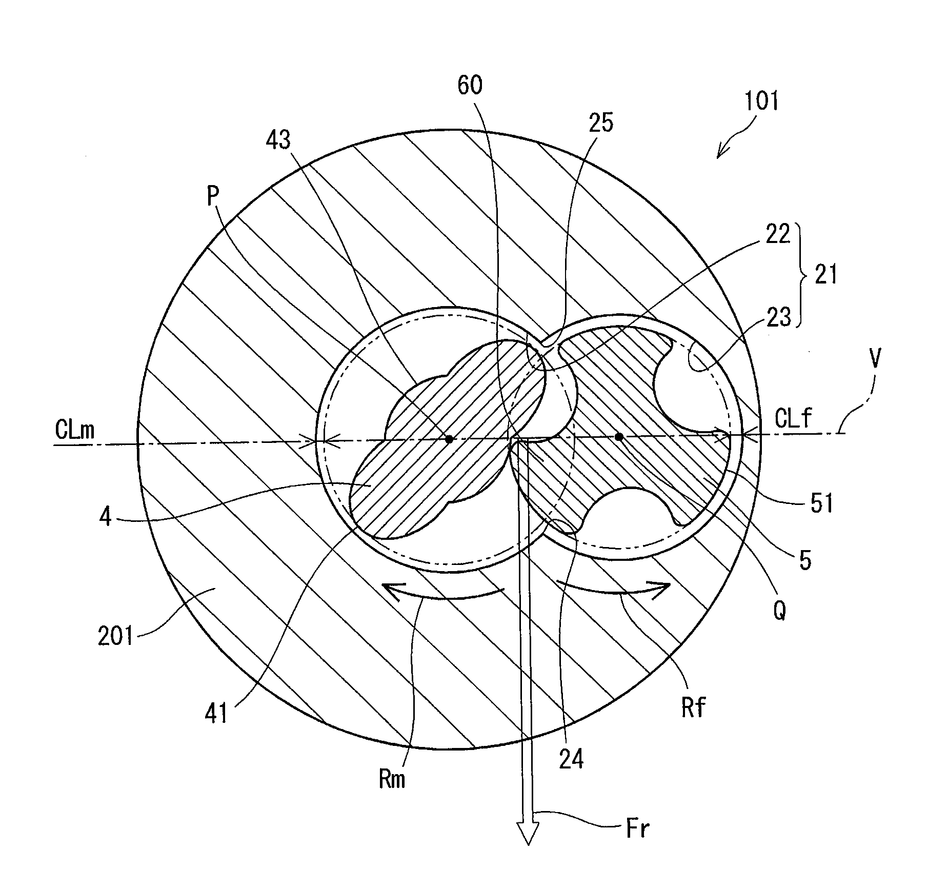
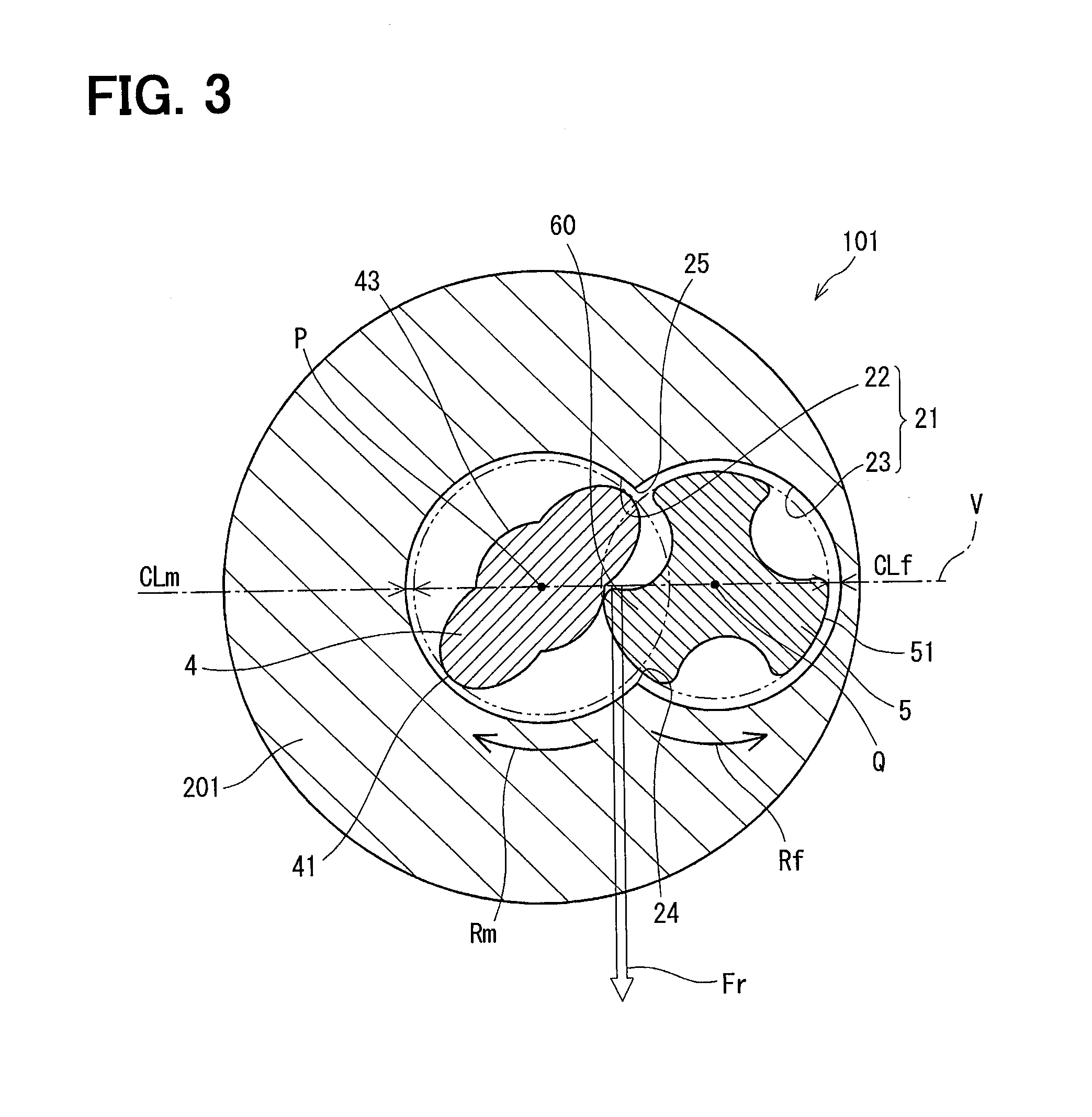
[0049] The pump housing 201, in particular, a relationship between the housing hole 21 and the screw members 4 and 5 will be explained more in detail. As shown in FIGS. 2 and 3, the pump housing 201 has the housing hole 21, which extends in the axial direction and accommodates the male screw member 4 and the female screw member 5. In FIG. 3, which shows a radial cross sectional view of the screw pump 101, taken along a line in FIG. 2, the housing hole 21 includes a male screw accommodation hole 22 for accommodating the male screw member 4 and a female screw accommodation hole 23 for accommodating the female screw member 5, wherein the male screw accommodation hole 22 and the female screw accommodation hole 23 are connected to each other in a peanut shape. An inner diameter of the male screw accommodation hole 22 is larger than that of the female screw accommodation hole 23. In the present disclosure, the male screw accommodation hole 22 corresponds to a driving-side screw accommodation hole, while the female screw accommodation hole 23 corresponds to a driven-side screw accommodation hole.
[0050] In the housing hole 21 of the peanut shape, there are two inwardly projecting portions respectively formed between the male screw accommodation hole 22 and the female screw accommodation hole 23. Each of the inwardly projecting portions extends in the axial direction of the pump housing 201. One of the inwardly projecting portions, which is located at a forward side of a rotation of the male screw member 4, is referred to as a forward-side boundary portion 24. The other of the inwardly projecting portions, which is located at a backward side of the rotation of the male screw member 4, is referred to as a backward-side boundary portion 25. The radial cross section of the housing hole 21 is symmetrically formed with respect to a virtual plane V extending in the axial direction. The virtual plane V is also referred to as a reference plane V.
[0051] As shown in FIG. 3, in a screw engagement area between the male screw member 4 and the female screw member 5, a lower-side area below the reference plane V corresponds to a forward-side engagement area of the rotation, while an upper-side area above the reference plane V corresponds to a backward-side engagement area of the rotation. In the screw engagement area, screw engagement portions 60 of the male screw member 4 and screw engagement portions 60 of the female screw member 5 are operatively in contact with or engaged with each other. The screw engagement portions 60 include a contact or an engagement portion of the male convex portion 41 and a contact or an engagement portion of the groove of the female screw member 5 as well as a contact or an engagement portion of the female convex portion 51 and a contact or an engagement portion of the groove 43 of the male screw member 4.
[0052] Pressure of the fuel flowing in the groove of a rotational backward side is higher than pressure of the fuel flowing in the groove of a rotational forward side, when compared them at the same axial height of the screw pump 101. In other words, the fuel pressure in the backward-side engagement area is higher than the fuel pressure in the forward-side engagement area. As a result, in the screw engagement area, a radial force Fr is generated in a direction from the rotational backward side to the rotational forward side, that is, from the backward-side engagement area to the forward-side engagement area.
[0053] The boundary portion between the male screw accommodation hole 22 and the female screw accommodation hole 23, which is located at a position of the rotational forward side in the screw engagement area, corresponds to the forward-side boundary portion 24.
[0054] A small radial gap of several ten microns (several ten pm) is formed in the radial direction of the screw pump 101 between an inner peripheral wall of the housing hole 21 and each radial-outward end of the male convex portion 41 and the female convex portion 51 of the screw members 4 and 5. A seal structure is thereby formed at the small radial gap. A working chamber 27 is formed between the inner peripheral wall of the housing hole 21 and each of the screw members 4 and 5 so as to compress the fuel F sucked from the suction port 11, as shown in FIG. 2. In each of the drawings from FIG. 3 to FIG. 8, the small radial gap is enlarged in order to show it in an easily understood manner.
[0055] As shown in FIG. 3, a male-side clearance "CLm" is formed between the male convex portion 41 and the inner peripheral wall of the male screw accommodation hole 22. The male-side clearance "CLm" continuously extends in a circumferential direction of the male screw accommodation hole 22 from the forward-side boundary portion 24 to the backward-side boundary portion 25 and has a constant value along the circumferential direction. A female-side clearance "CLf" is likewise formed between the female convex portion 51 and the inner peripheral wall of the female screw accommodation hole 23. The female-side clearance "CLf" continuously extends in a circumferential direction of the female screw accommodation hole 23 from the forward-side boundary portion 24 to the backward-side boundary portion 25 and has a constant value along the circumferential direction. The female-side clearance "CLf" is made to be larger than the male-side clearance "CLm" (CLf>CLm). In the present embodiment, the male-side clearance "CLm" corresponds to a first radial clearance, while the female-side clearance "CLf" corresponds to a second radial clearance.
(Operation and Advantages)
[0056] An operation of the screw pump 101 will be explained. When the male screw member 4 and the female screw member 5 are rotated by the electric motor 6, the fuel F is sucked into the working chamber 27 via the suction port 11. In this operation, the working chamber 27 is moved in the axial-upward direction from the lower-side cover 1 to the upper-side cover 3 in accordance with the rotation of the male screw member 4 and the female screw member 5.
[0057] When each of the male screw member 4 and the female screw member 5 is rotated by a predetermined angle, the working chamber 27 is communicated to the discharge port 32. Then, since an operational condition of the working chamber 27 is changed from a closed condition to an opened condition, the fuel Fin the working chamber 27 is discharged from the working chamber 27 to the outside of the screw pump 101 via the discharge port 32.
[0058] In the present embodiment, when any extraneous material, for example, sand or the like, enters the working chamber 27 during the operation of the screw pump 101, the female screw member 5 can move in a direction away from the male screw member 4 to the female screw accommodation hole 23, which has the female-side clearance "CLf" larger than the male-side clearance "CLm" of the male screw accommodation hole 22. Therefore, it is possible to prevent a locked condition of the screw members 4 and 5, which may be caused by the extraneous material wedged in a space between the male screw member 4 and the female screw member 5. In other words, the female-side clearance "CLf", which is made to be larger than the male-side clearance "CLm", works as an escape portion for the female screw member 5. The female-side clearance "CLf", which is made to be larger than the male-side clearance "CLm", is also referred to as "a clearance-enlarged portion". The female screw accommodation hole 23, for which the female-side clearance "CLf" is enlarged, corresponds to "a lock-prevention portion" for preventing the locked condition of the screw members 4 and 5, which would be caused by the extraneous material wedged between the screw members 4 and 5 and in which the screw members 4 and 5 are interlocked with each other.
[0059] In the screw pump of the above prior art (JP 2004-36547), the trap member is provided at the position of the side wall of the pump housing, in order to prevent the extraneous material from entering the screw pump. On the other hand, in the present embodiment, the lock-prevention portion is formed at the small radial gap in the housing hole 21. When compared the present embodiment with the screw pump of the prior art having the trap member, a size of the screw pump can be made to be smaller in the present embodiment.
[0060] Since it is not necessary in the present embodiment to provide a separate part, it is possible to reduce cost of the screw pump without increasing a number of parts. In addition, since the lock-prevention portion can be formed by simply increasing the inner diameter of the female screw accommodation hole 23, a manufacturing process of a hole drilling can be easily done.
[0061] In addition, in the present embodiment, the tooth width "W2" of the female screw member 5 is larger than the tooth width "W1" of the male screw member 4. The small radial gap (the female-side clearance "CLf") is made larger on a side of the female screw member 5, in which a sealing length is larger than that in the male screw member 4. It is thereby possible to make leakage loss smaller, when compared with a case in which the small radial gap (the male-side clearance "CLm") is made larger on a side of the male screw member 4.
Second Embodiment
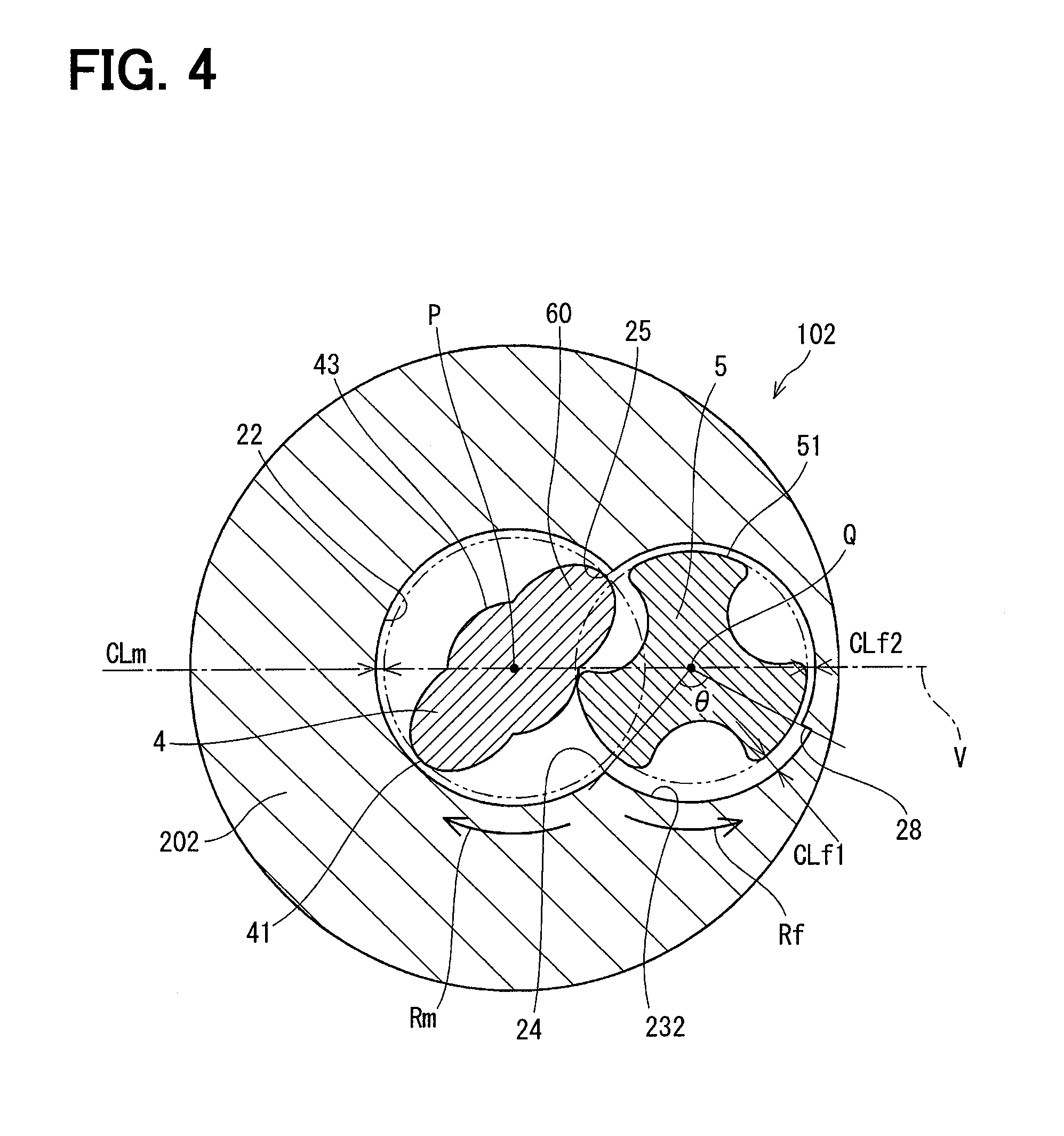
[0062] A screw pump 102 according to a second embodiment will be explained with reference to FIG. 4. The screw pump 102 of the second embodiment is different from the screw pump 101 of the first embodiment in a structure or a shape of the female screw accommodation hole.
[0063] As shown in FIG. 4, a stepped portion 28 is formed in a female screw accommodation hole 232 of a pump housing 202, wherein the stepped portion 28 extends in the axial direction. The stepped portion 28 is formed at a position, which is separated in the radial cross section from the forward-side boundary portion 24 in a circumferential direction of the female screw accommodation hole 232, more exactly, at a position separated from the forward-side boundary portion 24 in the rotational direction (in the anti-clockwise direction Rf) by an angle of 120 degrees. An inner diameter of the female screw accommodation hole 232 in a first inner surface area between the forward-side boundary portion 24 and the stepped portion 28 is different from that in a remaining area (a second inner surface area) of the female screw accommodation hole 232. The small radial gap between the female screw member 5 and the inner peripheral wall of the female screw accommodation hole 232 in the first inner surface area is referred to as a first female-side clearance "CLf1".
[0064] The small radial gap between the female screw member 5 and the inner peripheral wall of the female screw accommodation hole 232 in the second inner surface area (which is formed between the stepped portion 28 and the backward-side boundary portion 25) is referred to as a second female-side clearance "CLf2". The first female-side clearance "CLf1" is made to be larger than the second female-side clearance "CLf2". The second female-side clearance "CLf2" is equal to the male-side clearance "CLm". Each of the second female-side clearance "CLf2" and the male-side clearance "CLm" is set at such a value, with which a sealing performance can be sufficiently maintained between the screw member and the inner peripheral wall of the housing hole 21.
[0065] In the present embodiment, apart of the inner peripheral wall of the female screw accommodation hole 232 which has the first female-side clearance "CLf1", that is, a radial gap portion in the first inner surface area between the forward-side boundary portion 24 and the stepped portion 28, works as the escape portion for the female screw member 5. The first female-side clearance "CLf1" is formed in the first inner surface area from the forward-side boundary portion 24 to the stepped portion 28, which is an intermediate point between the forward-side boundary portion 24 and the backward-side boundary portion 25. A center angle ".theta." of the first female-side clearance "CLf1" is almost 120 degrees. In the first embodiment, the clearance-enlarged portion (the female-side clearance "CLf") is formed for an entire inner surface area of the female screw accommodation hole 23 in the circumferential direction. On the other hand, in the second embodiment, the clearance-enlarged portion (the first female-side clearance "CLf1") is formed for a limited inner surface area of the female screw accommodation hole 232 in the circumferential direction.
[0066] In the present embodiment, since the female screw member 5 is formed as the triple-thread screw, the first female-side clearance "CLf1" is formed for the circumferential portion of the inner peripheral wall of the female screw accommodation hole 232 having the center angle ".theta." of 120 degrees. Ina case that the female screw member 5 was formed as an N-thread screw, the first female-side clearance "CLf1" will be formed for a limited circumferential portion of the inner peripheral wall of the female screw accommodation hole 232 having the center angle ".theta." of 360/N degrees.
[0067] In the second embodiment, the same advantages to those of the first embodiment can be obtained. Since the first female-side clearance "CLf1", which is the clearance-enlarged portion working as the escape portion, is formed in the limited circumferential portion of the female screw accommodation hole 232, it is possible to reduce the leakage loss, which would be generated by making larger the radial gap between the screw member and the inner peripheral wall of the housing hole. As above, it is possible in the present embodiment to increase efficiency of the screw pump. In addition, the first female-side clearance "CLf1" is formed at the forward side of the rotation of the female screw member 5, at which the interlock of the screw members caused by the extraneous material is likely to occur. As a result, the female screw member 5 can smoothly move to the first female-side clearance "CLf1", when the extraneous material is going to be wedged between the male screw member 4 and the female screw member 5.
Third Embodiment
[0068] A screw pump 103 according to a third embodiment will be explained with reference to FIG. 5. The screw pump 103 of the third embodiment is different from the screw pump 102 of the second embodiment in the structure or the shape of the female screw accommodation hole.
[0069] In FIG. 5, a dotted line indicates the inner peripheral wall of the female screw accommodation hole 232 of the second embodiment, that is, the inner peripheral wall for the first inner surface area (the first female-side clearance "CLf1") formed between the forward-side boundary portion 24 and the stepped portion 28.
[0070] As shown in FIG. 5, an inner peripheral wall of a female screw accommodation hole 233 is formed in such a way that an inner diameter of the female screw accommodation hole 233 is gradually decreased in the rotational direction (in the anti-clockwise direction Rf) of the female screw member 5 in the first inner surface area from the forward-side boundary portion 24 to a circumferential intermediate point corresponding to the stepped portion 28 of the second embodiment, that is, the point separated in the circumferential direction from the forward-side boundary portion 24 by the angle of 120 degrees.
[0071] Even in the present embodiment, the same advantages to those of the second embodiment can be obtained. Since the radial gap between the female screw member 5 and the inner peripheral wall of the female screw accommodation hole 233 is gradually reduced in the first inner surface area (the clearance-enlarged portion), it is possible to further reduce the leakage loss.
Fourth Embodiment
[0072] A screw pump 104 according to a fourth embodiment will be explained with reference to FIG. 6. The screw pump 104 of the fourth embodiment is different from the screw pumps of the above embodiments in a structure of a female screw member 50.
[0073] In FIG. 6, a dotted line "L" shows an ideal line for an engagement between the male screw member 4 and the female screw member 50. More exactly, the ideal line "L" is a reference line, in which the radial gap between the male and the female screw members becomes zero when they are engaged with each other. As shown in FIG. 6, a pump housing 204 has a housing hole 211 and a female screw accommodation hole 234 is formed in the housing hole 211. The female screw member 50 is accommodated in the female screw accommodation hole 234.
[0074] In the present embodiment, a surface of a groove 53 of the female screw member 50 is further recessed in a radial-inward direction of the female screw member 50 from the reference line "L". A radial clearance between the surface of the groove 53 and the reference line "L" is set at a value "CLf3" at maximum.
[0075] As above, the groove 53 is so formed that the radial-outward end of the male convex portion 41 is not brought into contact with a bottom end of the groove 53, when the screw engagement portion 60 of the male convex portion 41 is engaged with the groove 53 of the female screw member 50. In other words, a space surrounded by the surface of the groove 53 and the reference line "L" works as the escape portion for the extraneous material. The groove 53 having the escape portion corresponds to the lock-prevention portion.
[0076] The interlock of the screw members 4 and 5 is likely to occur at such a portion, at which the radial-outward end of the male convex portion 41 is brought into contact with the groove 53, that is, at a portion neighboring to the reference line "L". However, in the present embodiment, the escape portion is formed in the groove 53 of the female screw member 50, so as to reduce probability of the interlock and to increase reliability of the screw pump.
Fifth Embodiment
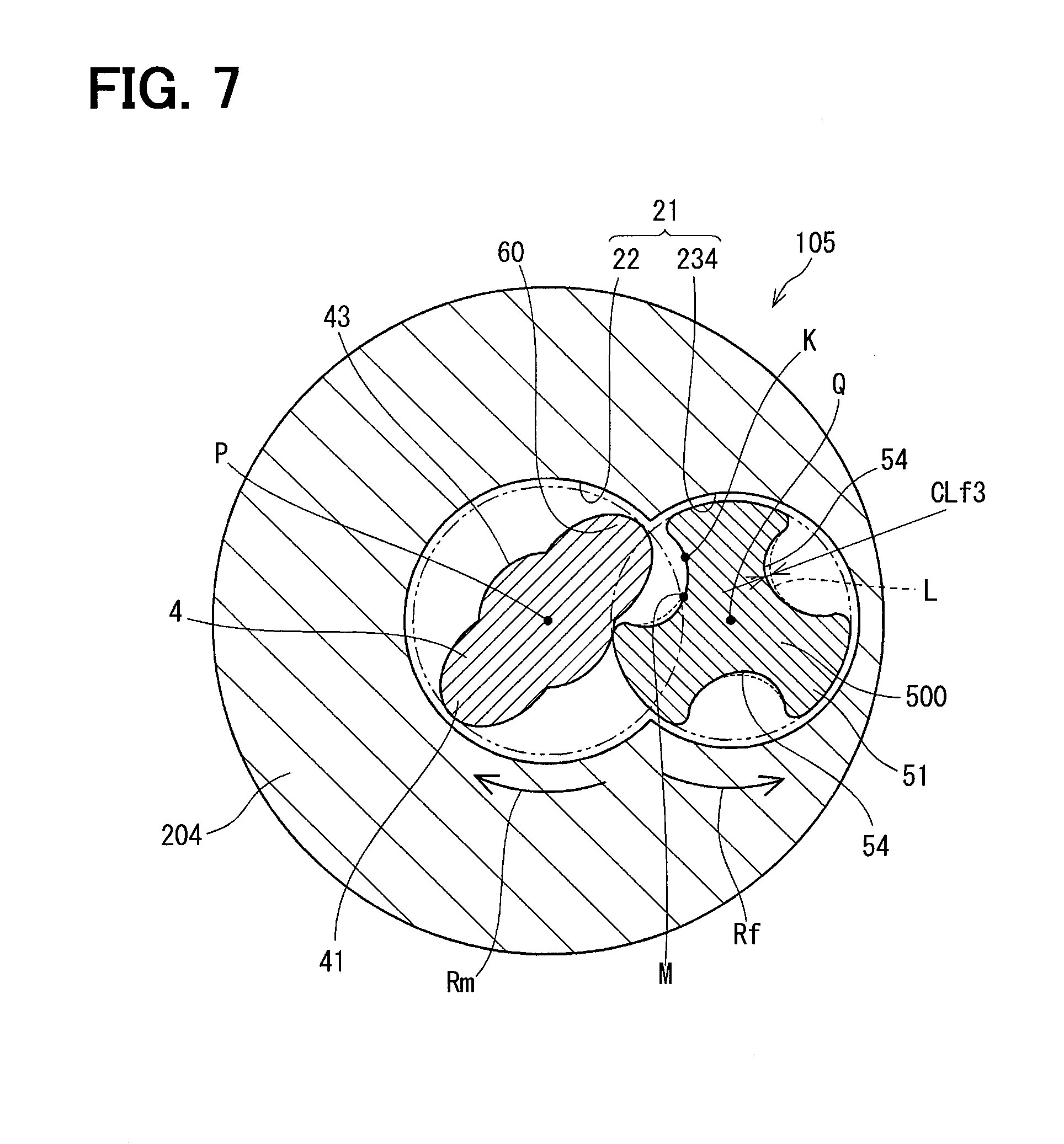
[0077] A screw pump 105 according to a fifth embodiment will be explained with reference to FIG. 7. The screw pump 105 of the fifth embodiment is different from the screw pump 104 of the fourth embodiment in a structure of a female screw member 500.
[0078] In FIG. 7, a dotted line "L" also shows the reference line for the engagement between the male screw member 4 and the female screw member 500.
[0079] As shown in FIG. 7, a surface of a groove 54 of the female screw member 500 is so formed that the surface of the groove 54 coincides with the shape of the reference line "L" in a backward-side groove area, that is, a portion from a point "K" to a point "M". The point "K" is a contact start point, at which a contact between the radial-outward end of the male convex portion 41 and the surface of the groove 54 starts. The point "M" is a middle point of the reference line "L" and a peak point of the contact between the male convex portion 41 and the groove 54. The surface of the groove 54 is further formed in a forward-side groove area in such a way that the surface of the groove 54 is recessed in the radial-inward direction of the female screw member 500 from the reference line "L", as indicated by a solid line. The groove 54, which has a recessed space working as the escape portion, corresponds to the lock-prevention portion.
[0080] In the present embodiment, since the escape portion is made smaller than that of the fourth embodiment, it is possible to further reduce the leakage loss and correspondingly improve the efficiency of the screw pump.
[0081] In the forward-side groove area, the extraneous material is more easily wedged between the screw members. However, since the escape portion for the extraneous material is formed at such a portion at which the interlock is likely to occur, the leakage loss can be reduced.
Sixth Embodiment
[0082] A screw pump 106 according to a sixth embodiment will be explained with reference to FIG. 8. The screw pump 106 of the sixth embodiment is different from the screw pump 102 of the second embodiment in a structure of the female accommodation hole 232.
[0083] As shown in FIG. 8, a low-rigidity layer 29 is provided on the inner peripheral wall of the female screw accommodation hole 232 in the first inner surface area of the first female-side clearance "CLf1". The low-rigidity layer 29 is made of, for example, a tinned layer, a coating of molybdenum dioxide and so on. The low-rigidity layer 29 is made of material, rigidity of which is lower than that of the pump housing 202. The radial gap between the female screw member 5 and the inner peripheral wall of the low-rigidity layer 29 provided in the female screw accommodation hole 232 is constantly formed at the value equal to the second female-side clearance "CLf2" even in the first inner surface area of the first female-side clearance "CLf1".
[0084] In the normal operation of the screw pump 106 in which no extraneous material enters, the low-rigidity layer 29 exists as it is. However, in a case that the extraneous material enters the screw pump 106 and the extraneous material is going to be wedged in the radial gap between the female screw member 5 and the inner peripheral wall of the female screw accommodation hole 232, a part of the low-rigidity layer 29 is chipped off by the female screw member 5.
[0085] As above, a high efficiency of the screw pump 106 can be maintained in the normal operation. The low-rigidity layer 29 works as the lock-prevention portion when the extraneous material enters the screw pump 106.
(Further Embodiments and/or Modifications)
[0086] In the above embodiments, the lock-prevention portion of each embodiment can be combined to one another.
[0087] For example, not only the female-side clearance "CLf" is formed between the female screw member 5 and the female screw accommodation hole 23 as the clearance-enlarged portion, as shown in the first embodiment (FIG. 3), but also the escape portion may be formed in the groove 53 of the female screw member 5, as shown in the fourth embodiment (FIG. 6). In such a combination, it is preferable to make each of the radial gaps further smaller to thereby make the leakage loss smaller as much as possible.
[0088] In the above third embodiment (FIG. 5), the clearance-enlarged portion is formed in the first inner surface area from the forward-side boundary portion 24 to the circumferential intermediate point separated therefrom by the angle of 120 degrees, in such a manner that the inner diameter of the female screw accommodation hole 233 is gradually decreased. However, the clearance-enlarged portion may extend in the circumferential direction to the backward-side boundary portion 25. Alternatively, the circumferential surface area for the clearance-enlarged portion may be arbitrarily changed.
[0089] In the above fourth and fifth embodiments (FIGS. 6 and 7), the recessed escape portion is formed in the groove 53/54 of the female screw member 50/500 as the escape portion, so that the escape portion works as the lock-prevention portion. The escape portion or the lock-prevention portion may be formed at any other portion of the engagement portion. For example, the escape portion may be formed in the groove 43 of the male screw member 4. In addition, it is not always necessary to form the escape portion in each of the grooves 53/54 of the female screw member 50/500. Namely, the escape portion(s) may be formed in one or two grooves 53/54.
[0090] In the above sixth embodiment (FIG. 8), the low-rigidity layer 29 is formed in the limited circumferential portion of the female screw accommodation hole 232. However, the low-rigidity layer 29 maybe formed in an entire inner peripheral wall of the female screw accommodation hole 232. Alternatively, the low-rigidity layer may be formed in the male screw accommodation hole 22. Furthermore, the low-rigidity layer may be formed in the groove 53/54 of the female screw member 50/500, more exactly, in the area surrounded by the reference line "L" and the surface of the groove 53/54 in the fourth or fifth embodiment (FIG. 6 or 7).
[0091] In the above first to third embodiments (FIGS. 1 to 5), the radial gap between the female screw member 5 and the female screw accommodation hole 23 (232, 233) is enlarged. However, the radial gap between the male screw member 4 and the male screw accommodation hole 22 may be enlarged to form the lock prevention portion.
[0092] In the above embodiments, the male screw member 4 is formed as the double-thread screw and the female screw member 5 (50, 500) is formed as the triple-thread screw. However, the type of the screw is not limited to the double-thread or the triple-thread screw.
[0093] In the above embodiments, the screw pump 101 (102, 103, 104, 105, 106) has one driving-side screw member and one driven-side screw member. However, it may be so modified that multiple driven-side screw members are provided around one driving-side screw member.
[0094] In the above embodiments, the female screw member may be used as the driving-side screw member and the male screw member may be used as the driven-side screw member.
[0095] A rotational-type actuator, which is operated by oil pressure or air pressure, may be used as the driving portion instead of the electric motor 6. The driving portion may be provided at a position outside of the upper-side cover.
[0096] The screw pump may be used as a pumping device for any fluid other than the fuel, for example, air.
[0097] The present disclosure is not limited to the above embodiments and/or the modifications but can be further modified in various manners without departing from a spirit of the present disclosure.
* * * * *
D00000
D00001
D00002
D00003
D00004
D00005
D00006
D00007
D00008
XML
uspto.report is an independent third-party trademark research tool that is not affiliated, endorsed, or sponsored by the United States Patent and Trademark Office (USPTO) or any other governmental organization. The information provided by uspto.report is based on publicly available data at the time of writing and is intended for informational purposes only.
While we strive to provide accurate and up-to-date information, we do not guarantee the accuracy, completeness, reliability, or suitability of the information displayed on this site. The use of this site is at your own risk. Any reliance you place on such information is therefore strictly at your own risk.
All official trademark data, including owner information, should be verified by visiting the official USPTO website at www.uspto.gov. This site is not intended to replace professional legal advice and should not be used as a substitute for consulting with a legal professional who is knowledgeable about trademark law.