Earth-boring Tools Including Rotatable Cutting Elements And Formation-engaging Features That Drive Rotation Of Such Cutting Elements, And Related Methods
Boehm; Alexander Rodney ; et al.
U.S. patent application number 15/704861 was filed with the patent office on 2019-03-14 for earth-boring tools including rotatable cutting elements and formation-engaging features that drive rotation of such cutting elements, and related methods. The applicant listed for this patent is Baker Hughes, a GE company, LLC. Invention is credited to Alexander Rodney Boehm, John Abhishek Raj Bomidi, Kegan L. Lovelace, William A. Moss, JR., Jon David Schroder.
| Application Number | 20190078392 15/704861 |
| Document ID | / |
| Family ID | 65630667 |
| Filed Date | 2019-03-14 |

| United States Patent Application | 20190078392 |
| Kind Code | A1 |
| Boehm; Alexander Rodney ; et al. | March 14, 2019 |
EARTH-BORING TOOLS INCLUDING ROTATABLE CUTTING ELEMENTS AND FORMATION-ENGAGING FEATURES THAT DRIVE ROTATION OF SUCH CUTTING ELEMENTS, AND RELATED METHODS
Abstract
An earth-boring tool includes a body and cutting elements rotatably mounted on the body. The earth-boring tool also includes a formation-engaging feature attached to the body and exposed at a face of the body. The formation-engaging feature may be configured to rotate about an axis of rotation responsive to frictional forces acting between the formation-engaging feature and a formation when the body moves relative to the formation. The axis of rotation of the formation-engaging feature may be oriented at an angle to an axis of rotation of the cutting elements. The formation-engaging feature may be operably coupled to the cutting elements such that rotation of the formation-engaging feature causes rotation of the cutting elements. Methods include drilling a subterranean formation including engaging a formation with the cutting elements and the formation-engaging features.
| Inventors: | Boehm; Alexander Rodney; (Wheat Ridge, CO) ; Schroder; Jon David; (The Woodlands, TX) ; Bomidi; John Abhishek Raj; (Spring, TX) ; Moss, JR.; William A.; (Conroe, TX) ; Lovelace; Kegan L.; (Houston, TX) | ||||||||||
| Applicant: |
|
||||||||||
|---|---|---|---|---|---|---|---|---|---|---|---|
| Family ID: | 65630667 | ||||||||||
| Appl. No.: | 15/704861 | ||||||||||
| Filed: | September 14, 2017 |
| Current U.S. Class: | 1/1 |
| Current CPC Class: | E21B 10/573 20130101; E21B 10/55 20130101; E21B 10/62 20130101 |
| International Class: | E21B 10/573 20060101 E21B010/573; E21B 10/55 20060101 E21B010/55 |
Claims
1. An earth-boring tool for drilling a subterranean formation, comprising: a body; at least one cutting element rotatably mounted on the body, the at least one cutting element comprising a table of polycrystalline hard material having an end cutting surface and a supporting substrate; a formation-engaging feature attached to the body and exposed at a face of the body, the formation-engaging feature configured to rotate about an axis of rotation responsive to frictional forces acting between the formation-engaging feature and a formation when the body moves relative to the formation, wherein the axis of rotation of the formation-engaging feature is oriented at an angle to an axis of rotation of the at least one cutting element; and wherein the formation-engaging feature is operably coupled to the at least one cutting element such that rotation of the formation-engaging feature causes rotation of the at least one cutting element.
2. The earth-boring tool of claim 1, further comprising: a first shaft extending from the formation-engaging feature and carrying a first gear; and a second shaft extending from the at least one cutting element and carrying a second gear; and wherein the first gear is engaged with the second gear.
3. The earth-boring tool of claim 2, wherein each of the first gear and the second gear comprises a miter gear.
4. The earth-boring tool of claim 2, wherein the first gear has a diameter greater than a diameter of the second gear.
5. The earth-boring tool of claim 2, wherein the first gear has a first tooth pattern, and the second gear has a second tooth pattern, the second tooth pattern differing from the first tooth pattern.
6. The earth-boring tool of claim 2, wherein an axis of rotation of the first shaft is substantially aligned with the axis of rotation of the formation-engaging feature, and an axis of rotation of the second shaft is substantially aligned with the axis of rotation of the at least one cutting element, and wherein the axis of rotation of the first shaft is generally perpendicular to the axis of rotation of the second shaft.
7. The earth-boring tool of claim 1, wherein the body comprises at least one blade having a recess therein, and the formation-engaging feature is mounted at least partially within the recess.
8. The earth-boring tool of claim 1, wherein the formation-engaging feature comprises a first rotational body and a second rotational body, the first rotational body of the formation-engaging feature being configured to rotate responsive to frictional forces acting between the first rotational body and the formation when the body moves relative thereto, and the second rotational body being configured to rotate responsive to rotation of the first rotational body.
9. The earth-boring tool of claim 8, wherein the first rotational body of the formation-engaging feature is operably coupled to the second rotational body of the formation-engaging feature by at least one of grooves, teeth, or frictional.
10. The earth-boring tool of claim 1, wherein the formation-engaging feature is operably coupled to the at least one cutting element such that one full revolution of the formation-engaging feature results in less than one full revolution of the at least one cutting element.
11. An earth-boring rotary drill bit, comprising: a bit body; a cutting element mounted on the bit body, the cutting element comprising a table of polycrystalline hard material having an end cutting surface and a supporting substrate, the cutting element being rotatable about a rotational axis; a formation-engaging feature attached to the bit body and exposed at a face of the bit body and configured to rotate about an axis of rotation responsive to frictional forces acting between the formation-engaging feature and a subterranean formation when the bit body moves relative to the subterranean formation, wherein the axis of rotation of the formation-engaging feature is oriented at an angle to an axis of rotation of the cutting element; and a flexible drive shaft operably coupled between the formation-engaging feature and the supporting substrate of the cutting element, the flexible drive shaft configured to apply torque to the supporting substrate of the cutting element so as to rotate the cutting element responsive to rotation of the formation-engaging feature.
12. The earth-boring rotary drill bit of claim 11, further comprising a plurality of rotatable cutting elements mounted on the bit body and a plurality of rotatable formation-engaging features attached to the bit body and exposed at a face of the bit body, each rotatable formation-engaging feature of the plurality of formation-engaging features being operably coupled with a respective one of the plurality of rotatable cutting elements such that rotation of each rotatable formation-engaging feature of the plurality of formation-engaging features drives rotation of a respective cutting element.
13. The earth-boring rotary drill bit of claim 11, wherein the face of the bit body includes a cone region, a nose region, a shoulder region, and a gage region, and wherein the cutting element is located in the shoulder region or the gage region of the face of the bit body.
14. The earth-boring rotary drill bit of claim 11, wherein the bit body includes blades having a leading edge, the cutting element is mounted at the leading edge of one of the blades, and the formation-engaging feature is located rotationally behind the cutting element.
15. The earth-boring rotary drill bit of claim 11, wherein the flexible drive shaft comprises non-alloy carbon steel material.
16. A method of drilling a subterranean formation, comprising: applying weight-on-bit to an earth-boring tool substantially along a longitudinal axis thereof and rotating the earth-boring tool; engaging a formation with a plurality of rotatable cutting elements located on blades of a bit body of the earth-boring tool, wherein the plurality of rotatable cutting elements are rotatably secured within pockets of the blades; engaging the formation with a formation-engaging feature attached to the bit body and exposed at a face of the earth-boring tool and configured to rotate about an axis of rotation thereof responsive to frictional forces acting between the formation-engaging feature and the formation when the earth-boring tool moves relative thereto; and driving rotation of at least one cutting element of the plurality of rotatable cutting elements responsive to rotation of the formation-engaging feature, wherein the axis of rotation of the formation-engaging feature is oriented at an angle to an axis of rotation of the at least one cutting element.
17. The method of claim 16, wherein driving rotation of the plurality of rotatable cutting elements comprises rotating a first shaft extending from the formation-engaging feature and carrying a first gear and rotating a second shaft extending from the at least one cutting element and carrying a second gear, wherein the first gear is engaged with the second gear.
18. The method of claim 17, wherein rotating the first shaft extending from the formation-engaging feature and carrying the first gear and rotating a second shaft extending from the at least one cutting element and carrying the second gear comprises the first gear having a diameter greater than a diameter of the second gear.
19. The method of claim 16, wherein the axis of rotation of the formation-engaging feature is perpendicular to an axis of rotation of the at least one cutting element.
20. The method of claim 16, wherein rotating the formation-engaging feature through one full revolution of the formation-engaging feature results in less than one full revolution of the at least one cutting element.
21. The method of claim 16, wherein engaging the formation with the formation-engaging feature comprises controlling a rate at which the formation-engaging feature extends and retracts from the face of the earth-boring tool using a hydraulic actuation device.
Description
FIELD
[0001] Embodiments of the present disclosure relate to earth-boring tools including rotatable cutting elements and formation-engaging features that drive rotation of such cutting elements, and to methods of drilling a subterranean formation using such earth-boring tools.
BACKGROUND
[0002] Wellbores are formed in subterranean formations for various purposes including, for example, extraction of oil and gas from the subterranean formation and extraction of geothermal heat from the subterranean formation. Wellbores may be formed in a subterranean formation using a drill bit, such as an earth-boring rotary drill bit. Different types of earth-boring rotary drill bits are known in the art, including fixed-cutter bits (which are often referred to in the art as "drag" bits), rolling-cutter bits (which are often referred to in the art as "rock" bits), diamond-impregnated bits, and hybrid bits (which may include, for example, both fixed cutters and rolling cutters). The drill bit is rotated and advanced into the subterranean formation. As the drill bit rotates, the cutters or abrasive structures thereof cut, crush, shear, and/or abrade away the formation material to form the wellbore. A diameter of the wellbore drilled by the drill bit may be defined by the cutting structures disposed at the largest outer diameter of the drill bit.
[0003] The drill bit is coupled, either directly or indirectly, to an end of what is referred to in the art as a "drill string," which comprises a series of elongated tubular segments connected end-to-end that extends into the wellbore from the surface of earth above the subterranean formations being drilled. Various tools and components, including the drill bit, may be coupled together at the distal end of the drill string at the bottom of the wellbore being drilled. This assembly of tools and components is referred to in the art as a "bottom hole assembly" (BHA).
[0004] The drill bit may be rotated within the wellbore by rotating the drill string from the surface of the formation, or the drill bit may be rotated by coupling the drill bit to a downhole motor, which is also coupled to the drill string and disposed proximate the bottom of the wellbore. The downhole motor may include, for example, a hydraulic Moineau-type motor having a shaft, to which the drill bit is mounted, that may be caused to rotate by pumping fluid (e.g., drilling mud or fluid) from the surface of the formation down through the center of the drill string, through the hydraulic motor, out from nozzles in the drill bit, and back up to the surface of the formation through the annular space between the outer surface of the drill string and the exposed surface of the formation within the wellbore. The downhole motor may be operated with or without drill string rotation.
[0005] A drill string may include a number of components in addition to a downhole motor and drill bit including, without limitation, drill pipe, drill collars, stabilizers, measuring while drilling (MWD) equipment, logging while drilling (LWD) equipment, downhole communication modules, and other components.
[0006] Cutting elements used in earth boring tools often include polycrystalline diamond compact (often referred to as "PDC") cutting elements, which are cutting elements that include so-called "tables" of a polycrystalline diamond material mounted to supporting substrates and presenting a cutting face for engaging a subterranean formation. Polycrystalline diamond (often referred to as "PCD") material is material that includes inter-bonded grains or crystals of diamond material. In other words, PCD material includes direct, intergranular bonds between the grains or crystals of diamond material.
[0007] Cutting elements are typically mounted on the body of a drill bit by brazing. The drill bit body is formed with recesses therein, commonly termed "pockets," for receiving a substantial portion of each cutting element in a manner which presents the PCD layer at an appropriate back rake and side rake angle, facing in the direction of intended bit rotation, for cutting in accordance with the drill bit design. In such cases, a brazing compound is applied between the surface of the substrate of the cutting element and the surface of the recess on the bit body in which the cutting element is received. The cutting elements are installed in their respective recesses in the bit body, and heat is applied to each cutting clement to raise the temperature to a point high enough to braze the cutting elements to the bit body in a fixed position but not so high as to damage the PCD layer.
[0008] Unfortunately, securing a PDC cutting element to a drill bit restricts the useful life of such cutting element, as the cutting edge of the diamond table wears down as does the substrate, creating a so-called "wear flat" and necessitating increased weight on bit to maintain a given rate of penetration of the drill bit into the formation due to the increased surface area presented. In addition, unless the cutting element is heated to remove it from the bit and then rebrazed with an unworn portion of the cutting edge presented for engaging a formation, more than half of the cutting element is never used.
[0009] Rotatable cutting elements mounted for rotation about a longitudinal axis of the cutting element can be made to rotate by mounting them at an angle in the plane in which the cutting elements are rotating (side rake angle). This will allow them to wear more evenly than fixed cutting elements, having a more uniform distribution of heat across and heat dissipation from the surface of the PDC table and exhibit a significantly longer useful life without removal from the drill bit. That is, as a cutting element rotates in a bit body, different parts of the cutting edges or surfaces of the PDC table may be exposed at different times, such that more of the cutting element is used. Thus, rotatable cutting elements may have a longer life than fixed cutting elements.
[0010] Additionally, rotatable cutting elements may mitigate the problem of "bit balling," which is the buildup of debris adjacent to the edge of the cutting face of the PDC table. As the PDC table rotates, the debris built up at the edge of the PDC table in contact with a subterranean formation may be forced away as the PDC table rotates.
BRIEF SUMMARY
[0011] In one embodiment of the disclosure, an earth-boring tool for drilling a subterranean formation includes a body and one or more cutting elements rotatably mounted on the body. The cutting elements may include a table of polycrystalline hard material having an end cutting surface and a supporting substrate. The earth-boring tool also includes a formation-engaging feature attached to the body and exposed at a face of the body. The formation-engaging feature may be configured to rotate about an axis of rotation responsive to frictional forces acting between the formation-engaging feature and a formation when the body moves relative to the formation. The axis of rotation of the formation-engaging feature may be oriented at an angle to an axis of rotation of the cutting elements. The formation-engaging feature may be operably coupled to the cutting elements such that rotation of the formation-engaging feature causes rotation of the cutting elements.
[0012] In another embodiment of the disclosure, an earth-boring rotary drill bit includes a bit body and a cutting element mounted on the bit body. The cutting element includes a table of polycrystalline hard material having an end cutting surface and a supporting substrate. The cutting element may be rotatable about a rotational axis. The earth-boring rotary drill bit also includes a formation-engaging feature attached to the bit body and exposed at a face of the bit body. The formation-engaging feature may be configured to rotate about an axis of rotation responsive to frictional forces acting between the formation-engaging feature and a subterranean formation when the bit body moves relative to the subterranean formation. The axis of rotation of the formation-engaging feature may be oriented at an angle to an axis of rotation of the cutting element. The earth-boring rotary drill bit may also include a flexible drive shaft operably coupled between the formation-engaging feature and the supporting substrate of the cutting element. The flexible drive shaft may be configured to apply torque to the supporting substrate of the cutting element so as to rotate the cutting element responsive to rotation of the formation-engaging feature.
[0013] In a further embodiment of the disclosure, a method of drilling a subterranean formation includes applying weight-on-bit to an earth-boring tool substantially along a longitudinal axis thereof and rotating the earth-boring tool. The method may include engaging a formation with rotatable cutting elements located on blades of a bit body of the earth-boring tool. The rotatable cutting elements may be rotatably secured within pockets of the blades. The method also includes engaging the formation with a formation-engaging feature attached to the bit body and exposed at a face of the earth-boring tool. The formation-engaging feature may be configured to rotate about an axis of rotation thereof responsive to frictional forces acting between the formation-engaging feature and the formation when the earth-boring tool moves relative thereto. The method may also include driving rotation of one of the cutting elements of the rotatable cutting elements responsive to rotation of the formation-engaging feature. The axis of rotation of the formation-engaging feature may be oriented at an angle to an axis of rotation of the cutting element.
BRIEF DESCRIPTION OF THE DRAWINGS
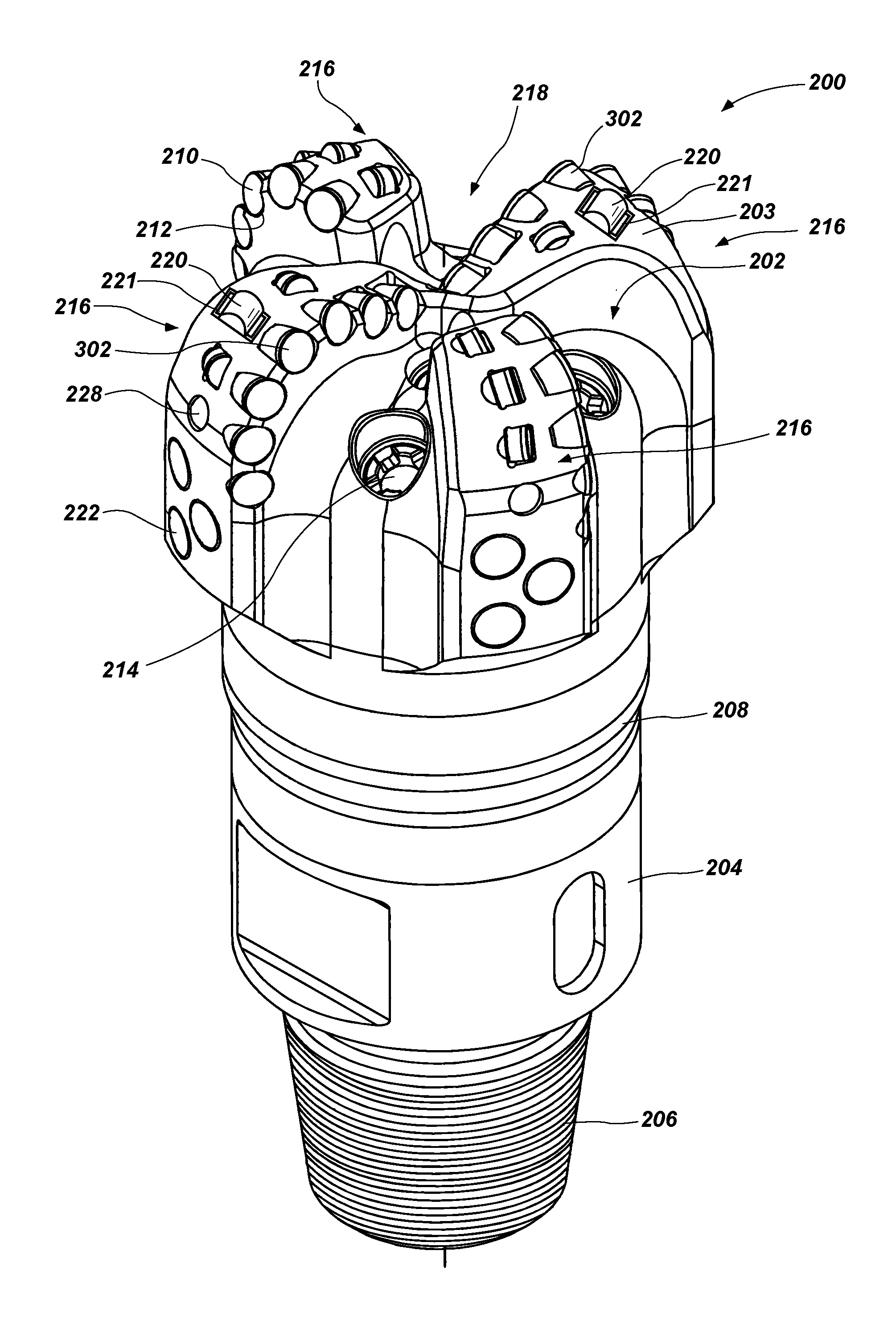
[0014] FIG. 1 is a simplified perspective view of a fixed-blade earth-boring rotary drill bit.
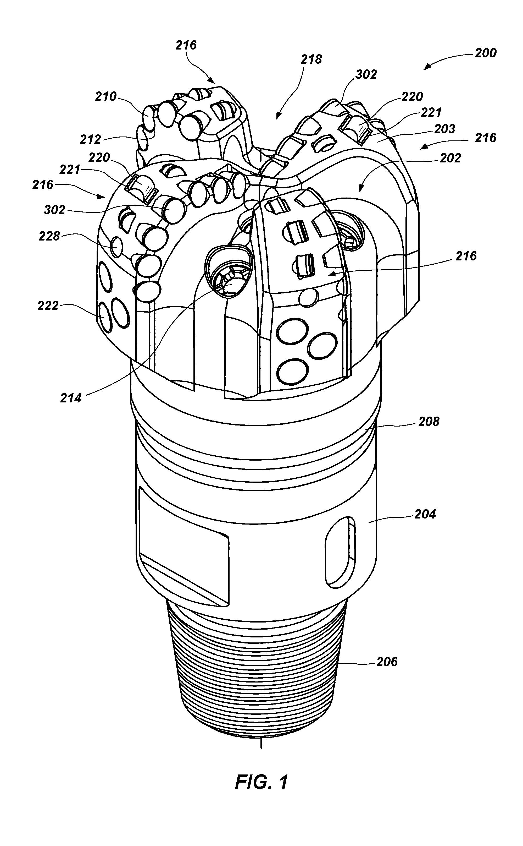
[0015] FIG. 2 is a simplified perspective view of a rotatable cutting element that may be used in conjunction with a formation-engaging feature as shown in FIG. 1.
[0016] FIG. 3 is a simplified top view of an embodiment of a formation-engaging assembly that may be used in conjunction with a rotatable cutting element, such as the one shown in FIG. 2.
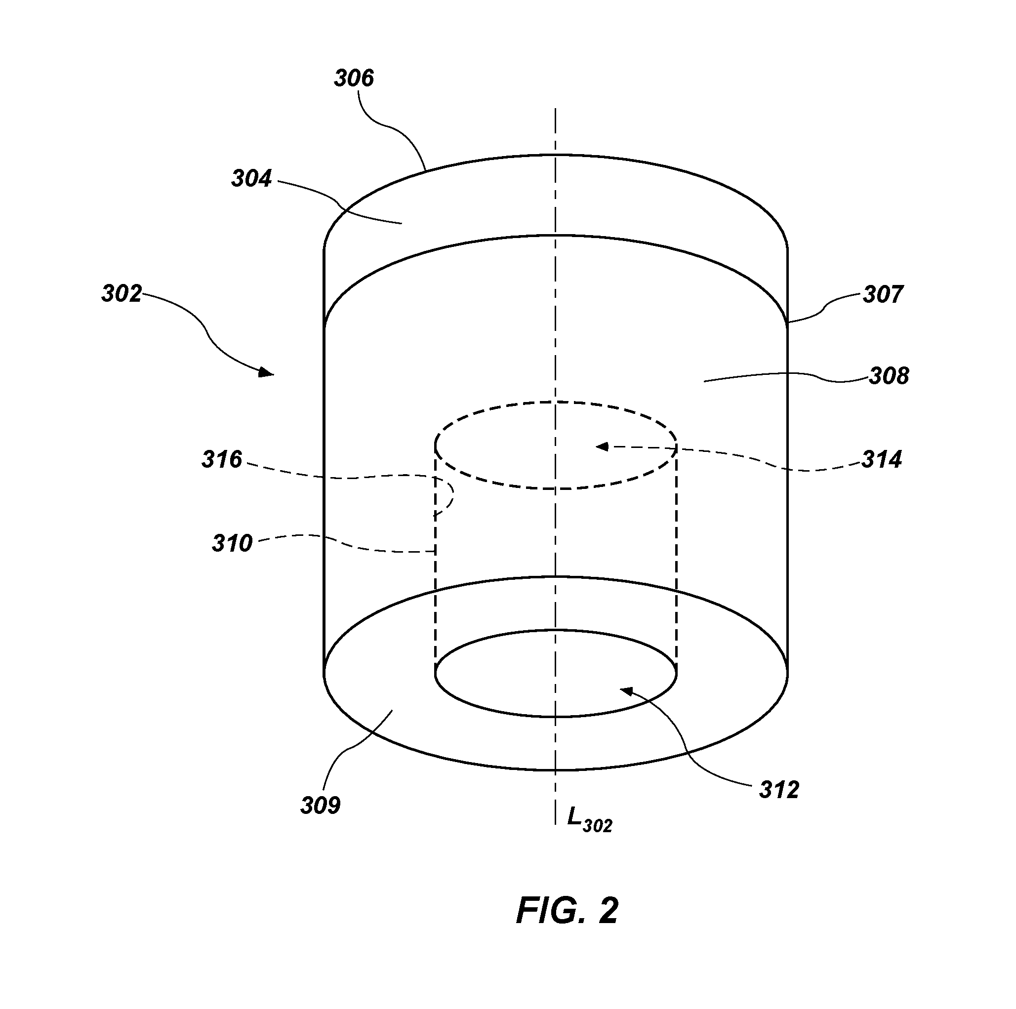
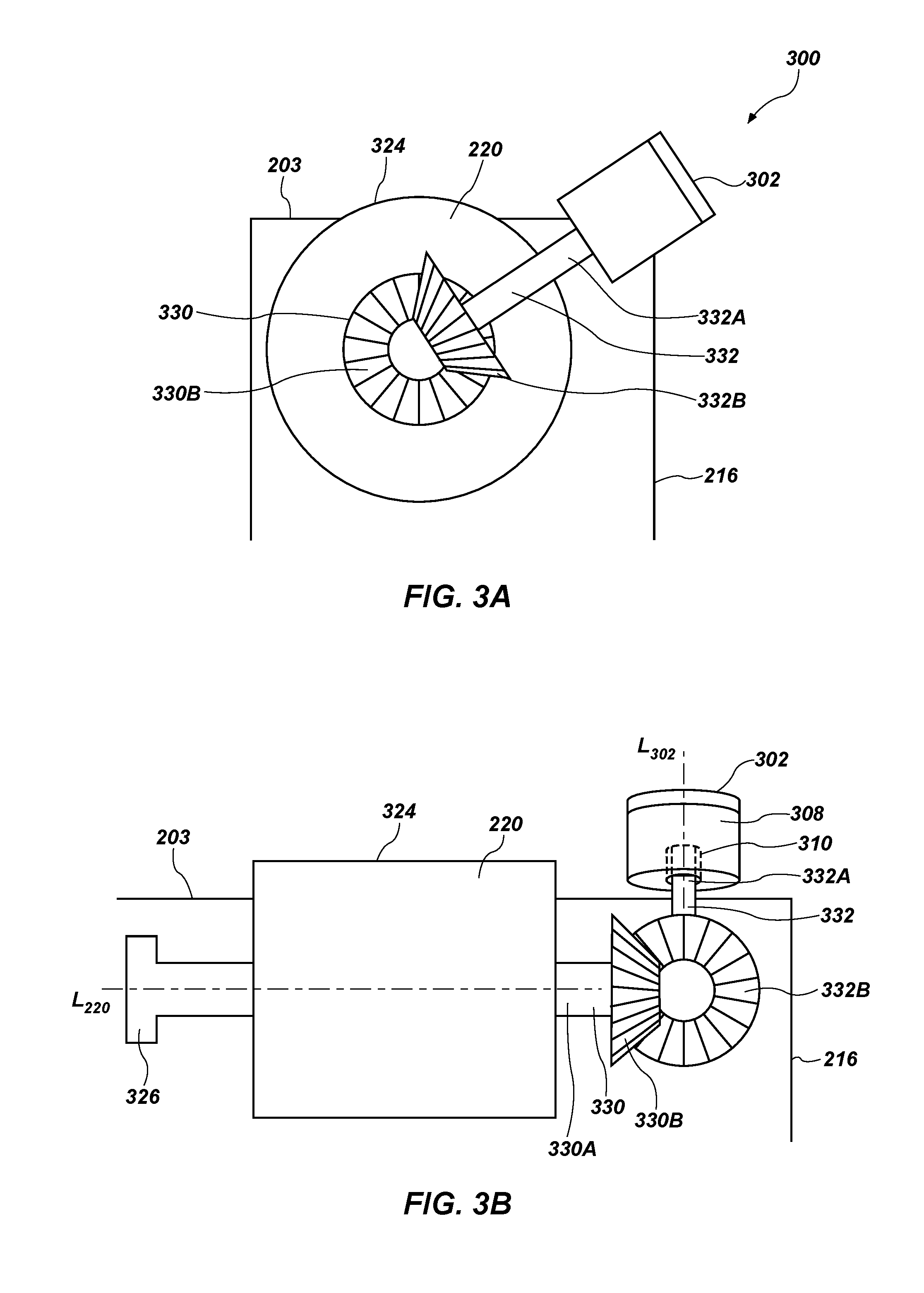
[0017] FIG. 3A is a simplified end view of the formation-engaging assembly shown in FIG. 3.
[0018] FIG. 3B is a simplified cross-sectional side view of the formation-engaging assembly shown in FIG. 3.
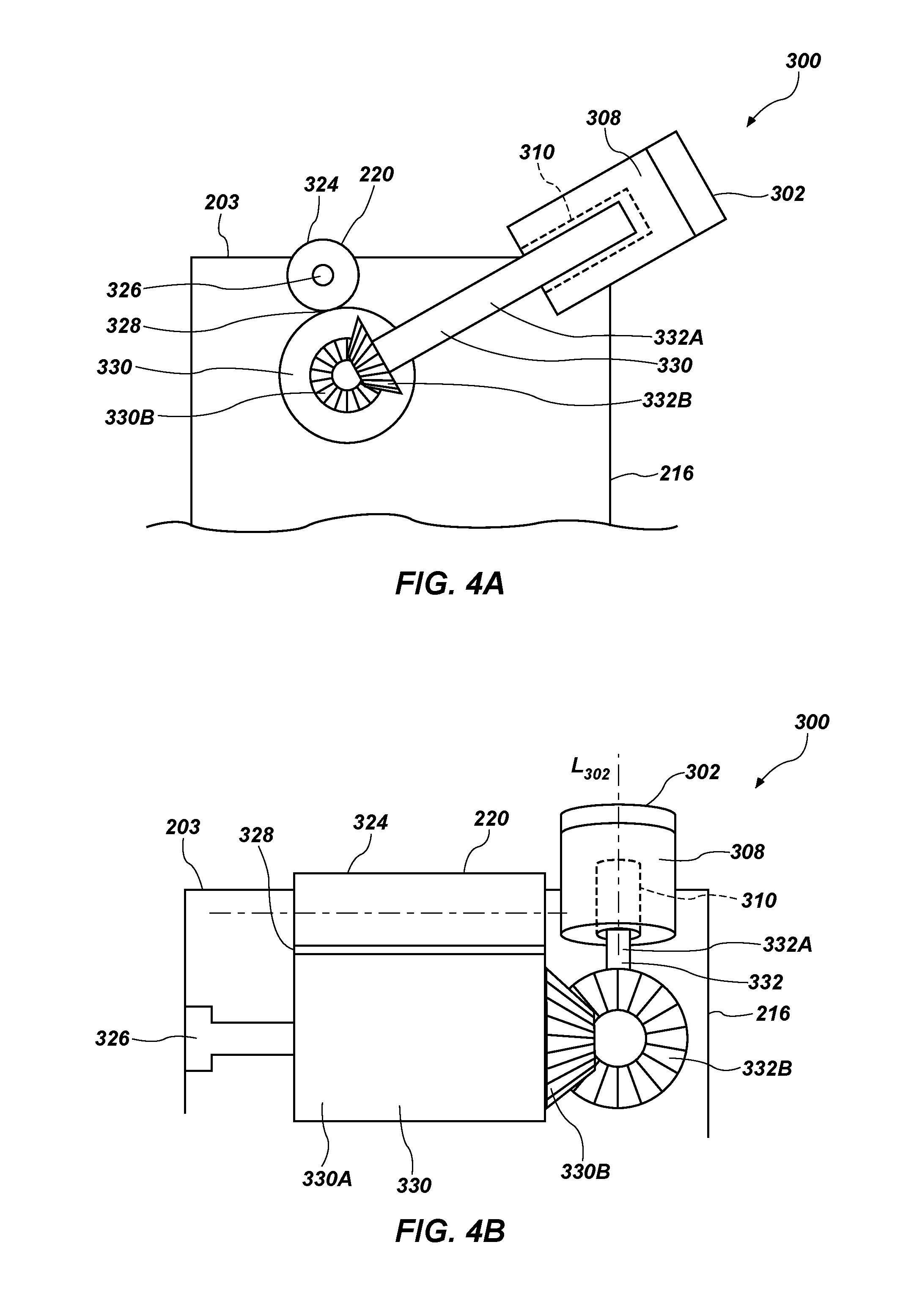
[0019] FIG. 4A is a simplified end view of another embodiment of a formation-engaging assembly that may be used in conjunction with a rotatable cutting element, such as the one shown in FIG. 2.
[0020] FIG. 4B is a simplified cross-sectional side view of the formation-engaging assembly shown in FIG. 4A.
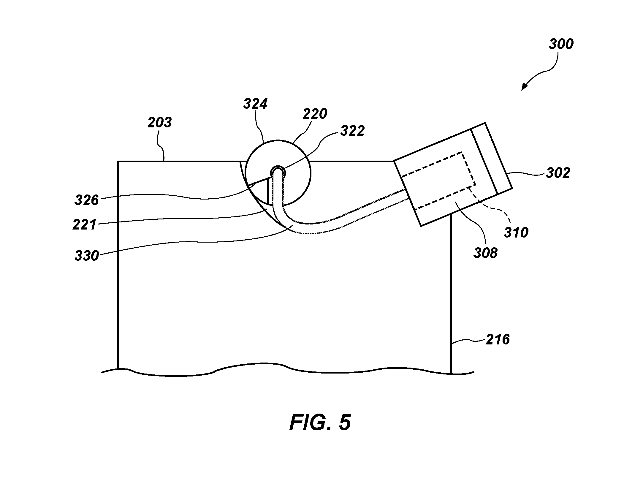
[0021] FIG. 5 is a simplified end view of another embodiment of a formation-engaging assembly that may be used in conjunction with a rotatable cutting element, such as the one shown in FIG. 2.
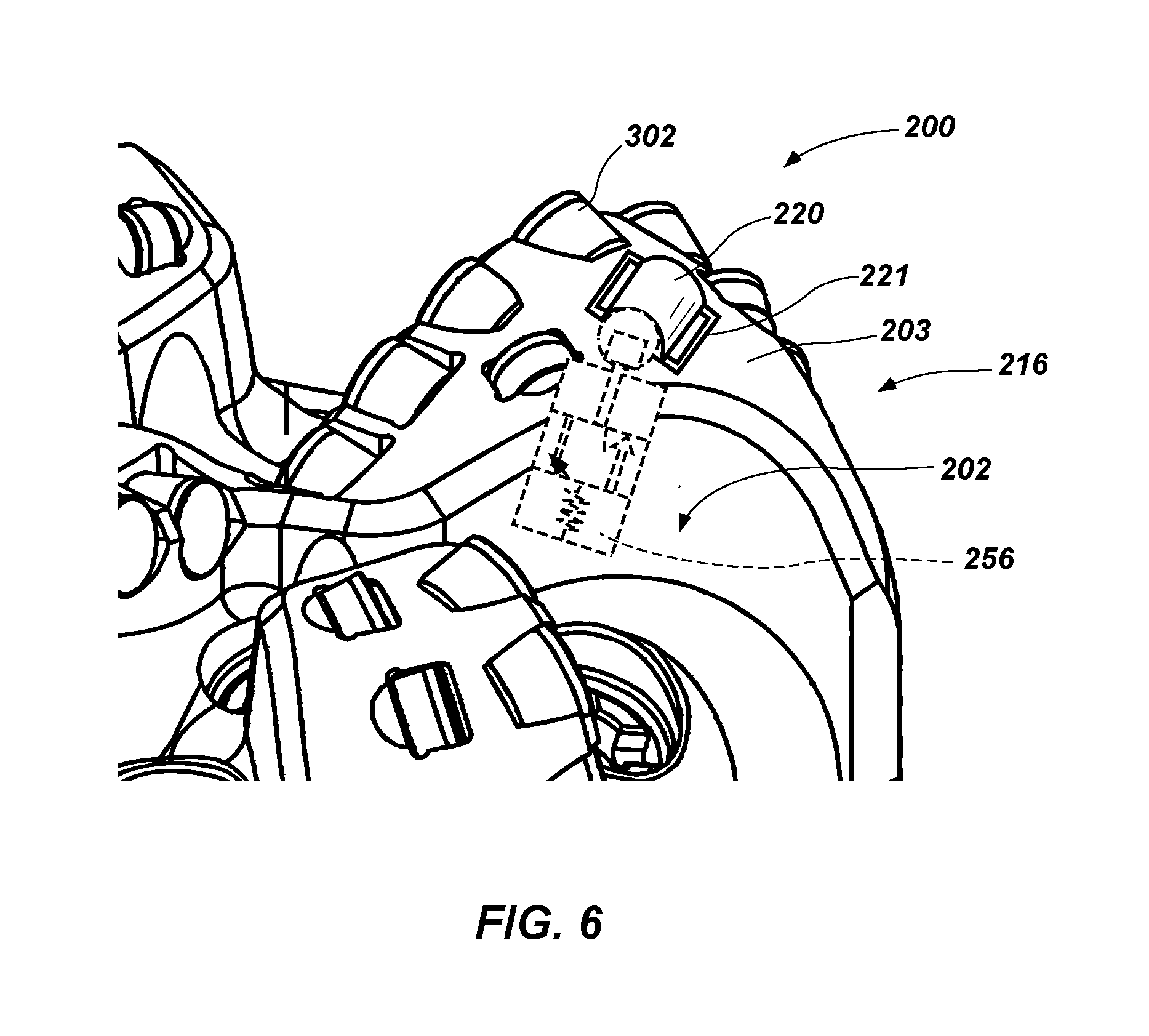
[0022] FIG. 6 is a simplified perspective view of a portion of the fixed-blade earth-boring rotary drill bit of FIG. 1.
DETAILED DESCRIPTION
[0023] The illustrations presented herein are not actual views of any particular tool or drill string, but are merely idealized representations that are employed to describe example embodiments of the present disclosure. The following description provides specific details of embodiments of the present disclosure in order to provide a thorough description thereof. However, a person of ordinary skill in the art will understand that the embodiments of the disclosure may be practiced without employing many such specific details. Indeed, the embodiments of the disclosure may be practiced in conjunction with conventional techniques employed in the industry. In addition, the description provided below does not include all elements to form a complete structure or assembly. Only those process acts and structures necessary to understand the embodiments of the disclosure are described in detail below. Additional conventional acts and structures may be used. Also note, any drawings accompanying the application are for illustrative purposes only, and are thus not drawn to scale. Additionally, elements common between figures may retain the same numerical designation.
[0024] As used herein, the terms "comprising," "including," "containing," "characterized by," and grammatical equivalents thereof are inclusive or open-ended terms that do not exclude additional, unrecited elements or method steps, but also include the more restrictive terms "consisting of" and "consisting essentially of" and grammatical equivalents thereof.
[0025] As used herein, the term "may" with respect to a material, structure, feature or method act indicates that such is contemplated for use in implementation of an embodiment of the disclosure, and such term is used in preference to the more restrictive term "is" so as to avoid any implication that other, compatible materials, structures, features and methods usable in combination therewith should or must be excluded.
[0026] As used herein, the term "configured" refers to a size, shape, material composition, and arrangement of one or more of at least one structure and at least one apparatus facilitating operation of one or more of the structure and the apparatus in a predetermined way.
[0027] As used herein, the singular forms following "a," "an," and "the" are intended to include the plural forms as well, unless the context clearly indicates otherwise.
[0028] As used herein, the term "and/or" includes any and all combinations of one or more of the associated listed items.
[0029] As used herein, spatially relative terms, such as "beneath," "below," "lower," "bottom," "above," "upper," "top," "front," "rear," "left," "right," and the like, may be used for ease of description to describe one element's or feature's relationship to another element(s) or feature(s) as illustrated in the figures. Unless otherwise specified, the spatially relative terms are intended to encompass different orientations of the materials in addition to the orientation depicted in the figures.
[0030] As used herein, the term "substantially" in reference to a given parameter, property, or condition means and includes to a degree that one of ordinary skill in the art would understand that the given parameter, property, or condition is met with a degree of variance, such as within acceptable manufacturing tolerances. By way of example, depending on the particular parameter, property, or condition that is substantially met, the parameter, property, or condition may be at least 90.0% met, at least 95.0% met, at least 99.0% met, or even at least 99.9% met.
[0031] As used herein, the term "about" used in reference to a given parameter is inclusive of the stated value and has the meaning dictated by the context (e.g., it includes the degree of error associated with measurement of the given parameter).
[0032] As used herein, the term "hard material" means and includes any material having a Knoop hardness value of about 1,000 Kg.sub.f/mm.sup.2 (9,807 MPa) or more. Hard materials include, for example, diamond, cubic boron nitride, boron carbide, tungsten carbide, etc.
[0033] As used herein, the term "intergranular bond" means and includes any direct atomic bond (e.g., covalent, metallic, etc.) between atoms in adjacent grains of material.
[0034] As used herein, the term "polycrystalline hard material" means and includes any material comprising a plurality of grains or crystals of the material that are bonded directly together by intergranular bonds. The crystal structures of the individual grains of polycrystalline hard material may be randomly oriented in space within the polycrystalline hard material.
[0035] As used herein, the term "earth-boring tool" means and includes any type of bit or tool used for drilling during the formation or enlargement of a wellbore and includes, for example, rotary drill bits, percussion bits, core bits, eccentric bits, bi-center bits, reamers, mills, drag bits, roller-cone bits, hybrid bits, and other drilling bits and tools known in the art.
[0036] Embodiments of the present disclosure include cutting elements rotatably mounted on a body of an earth-boring tool. Formation-engaging features attached to the body and exposed at a face of the body may be configured to drive rotation of the rotatable cutting elements responsive to frictional forces acting between the formation-engaging features and a subterranean formation. Further, operably coupling such formation-engaging features to the rotatable cutting elements may provide the advantage of selecting mating surfaces therebetween to impart increased torque to the rotatable cutting elements.
[0037] FIG. 1 is a perspective view of a fixed-cutter earth-boring rotary drill bit 200. The drill bit 200 includes a bit body 202 that may be secured to a shank 204 having a threaded connection portion 206 (e.g., an American Petroleum Institute (API) threaded connection portion) for attaching the drill bit 200 to a drill string. In some embodiments, the bit body 202 may be secured to the shank 204 using an extension 208. In other embodiments, the bit body 202 may be secured directly to the shank 204.
[0038] The bit body 202 may include internal fluid passageways that extend between the face 203 of the bit body 202 and a longitudinal bore, extending through the shank 204, the extension 208, and partially through the bit body 202. Nozzle inserts 214 also may be provided at the face 203 of the bit body 202 within the internal fluid passageways. The bit body 202 may further include a plurality of blades 216 that are separated by junk slots 218. In some embodiments, the bit body 202 may include gage wear plugs 222 and wear knots 228. A plurality of fixed cutting elements 210 may be mounted on the face 203 of the bit body 202 in cutting element pockets 212 that are located along each of the blades 216. Rotatable cutting elements 302 may be rotatably mounted on the face 203 of the bit body 202 in respective cutting element pockets 212. The fixed cutting elements 210 and the rotatable cutting elements 302 may include PDC cutting elements, or may include other cutting elements. In addition, formation-engaging features 220 may be fastened within respective recesses 221 at the face 203 of the bit body 202. The formation-engaging features 220 may be configured to drive rotation of at least some of the rotatable cutting elements 302 responsive to frictional forces acting between the formation-engaging features 220 and a subterranean formation when the bit body 202 moves relative thereto, as described below and shown in FIGS. 2-5.
[0039] FIG. 2 is a simplified perspective view of one embodiment of the rotatable cutting element 302. The rotatable cutting element 302 may be used, for example, in conjunction with formation-engaging features 220 shown in FIG. 1. The rotatable cutting element 302 may include a table 304 (e.g., a table of polycrystalline hard material) bonded to a substrate 308 at an interface 307. The table 304 may include diamond, cubic boron nitride, or another hard material. The substrate 308 may include, for example, cobalt-cemented tungsten carbide or another carbide material. The table 304 may have an end cutting surface 306, and may also have other surfaces, such as side surfaces, chamfers, etc., at a peripheral cutting edge of the table 304, which surfaces contact a subterranean formation when the rotatable cutting element 302 is used to form or service a wellbore. The table 304 may be generally cylindrical, and the interface 307 may be generally parallel to the end cutting surface 306. The substrate 308 may have a bearing surface 309 on an end thereof, opposite the interface 307. In this embodiment, the bearing surface 309 may be planar and annular. In addition, the end cutting surface 306 of the table 304 may be planar and annular. In other embodiments, the bearing surface 309 may be nonplanar and/or the end cutting surface may include a nonplanar, convex cutting table not having a flat cutting face (e.g., dome-shaped, cone-shaped, chisel-shaped, etc.). In some embodiments, the end cutting surface 306 may be treated (e.g., polished) to exhibit a reduced surface roughness.
[0040] Interior surfaces of the substrate 308 of the rotatable cutting element 302 may define a longitudinally extending blind hole 310 having a proximal end 312 at the bearing surface 309 of the substrate 308 and having a distal end 314 within the substrate 308 proximate the interface 307 between the substrate 308 and the table 304. In some embodiments, the blind hole 310 may not extend to the table 304 (i.e., may terminate within the substrate 308). The blind hole 310 is defined by an interior sidewall 316 of the rotatable cutting element 302 and may be generally centered along a longitudinal axis L.sub.302 of the rotatable cutting element 302. The blind hole 310 may impart an annular cross-sectional shape to the rotatable cutting element 302. In some embodiments, at least a portion of the interior sidewall 316 may include structures (e.g., channels, grooves, protrusions, threads, etc.) formed therein to facilitate retention and/or alignment of the rotatable cutting element 302 with respect to features inserted within the blind hole 310. Such structures may align with complementary structures on inserted features.
[0041] FIG. 3 shows a simplified top view of one embodiment of a formation-engaging assembly 300. Elements shown in dashed lines may not be visible from a top view of the blade 216, but are included in FIG. 3 for clarity. The formation-engaging assembly 300 may include cutting elements, such as the fixed cutting elements 210 as well as one or more of the rotatable cutting elements 302 shown in FIG. 2. The formation-engaging assembly 300 may also include formation-engaging features 220 having a longitudinal axis L.sub.220. In some embodiments, the formation-engaging feature 220 may be generally cylindrical and have an interior sidewall 322 and an exterior sidewall 324. The formation-engaging feature 220 may include an attachment feature 326 for fastening (e.g., brazing) at least a portion of the formation-engaging feature 220 within the recess 221. The formation-engaging feature 220 may also include an engagement feature 330 having a shaft 330A and a mating surface 330B, for example. The rotatable cutting element 302 may include an impelling feature 332 having a shaft 332A and a mating surface 332B, for example.
[0042] The fixed cutting elements 210 may be brazed or fastened within respective cutting element pockets 212 of the blades 216. In addition, the rotatable cutting elements 302 may be rotatably fastened within respective cutting element pockets 212 configured for retaining such elements. Of course, a person of ordinary skill in the art would recognize that lateral support of the rotatable cutting elements 302 would be desirable in order to protect against impact damage and/or to support the rotatable cutting elements 302 located within the cutting element pockets 212 machined (e.g., in steel bodies) or otherwise formed in the blades 216 of the bit body 202 (FIG. 1) or supported by preformed sleeves that have been brazed or otherwise fastened within the respective cutting element pockets 212 of the blades 216. The formation-engaging features 220 may be attached to the bit body 202 and exposed at the face 203 of the bit body 202 (FIG. 1) and configured to engage a formation during drilling operations. For example, the formation-engaging feature 220 may be located proximate to (e.g., rotationally behind) the rotatable cutting elements 302 on the blades 216. In some embodiments, the exterior sidewall 324 of the formation-engaging feature 220 may include features (e.g., grooves, veins, textured surface finish, etc.) to enhance frictional forces acting thereon to facilitate rotation of the formation-engaging feature 220 upon interaction with the engaged formation. Materials of the formation-engaging feature 220 may include a metal carbide or steel material (e.g., high-strength steel alloy). For example, the formation-engaging feature 220, including the attachment feature 326, may include materials such as tungsten carbide, tantalum carbide, or titanium carbide. Additionally, various binding metals may be included in the formation-engaging feature 220, such as cobalt, nickel, iron, metal alloys, or mixtures thereof, such that metal carbide grains may be supported within the metallic binder.
[0043] The formation-engaging feature 220 may be fastened within a respective recess 221 of the blades 216 utilizing the attachment feature 326. In some embodiments, the attachment feature 326 may include support members (e.g., sleeves) that retain the formation-engaging feature 220 utilizing retention members (e.g., snap rings). Such support members may secure the formation-engaging feature 220 to the blade 216 and enable the formation-engaging feature 220 to move relative to the blades 216. It is to be appreciated that any type of attachment feature 326 may be utilized to facilitate attachment of the formation-engaging feature 220 within the recess 221 without interfering with rotation thereof.
[0044] The shaft 330A of the formation-engaging feature 220 may be affixed thereto (e.g., within a through hole or blind hole defined by the interior sidewall 322). In other embodiments, the shaft 330A may be integrally formed with the formation-engaging feature 220, such that there is no physical interface between the shaft 330A and the formation-engaging feature 220. The mating surface 330B may be affixed to or integrally formed with the shaft 330A. In some embodiments, the mating surface 330B may include a gear (e.g., bevel, miter, etc.). In other embodiments, the mating surface 330B may include a spur gear (e.g., straight-cut gear). The engagement feature 330, including the shaft 330A and/or the mating surface 330B, may be formed of the same material as the formation-engaging feature 220. In yet other embodiments, the mating surface 330B may not include a gear, but may include any other surface or interface for operatively coupling the engagement feature 330 of the formation-engaging feature 220 to features of the rotatable cutting element 302. In addition, the shaft 332A of the impelling feature 332 may be affixed (e.g., brazed) to the interior sidewall 316 defining the blind hole 310. In other embodiments, the shaft 332A of the impelling feature 332 may be integrally formed with the substrate 308, such that there is no physical interface between the shaft 332A and the substrate 308 of the rotatable cutting element 302. The mating surface 332B may be affixed to or integrally formed with the shaft 332A. In some embodiments, the mating surface 332B may include a gear (e.g., bevel, miter, etc.) that is complementary to the mating surface 330B of the engagement feature 330. In other embodiments, the mating surface 332B may include a spur gear (e.g., straight-cut gear) or other such surface or interface to be aligned with the mating surface 330B. In some embodiments, the impelling feature 332, including the shaft 332A and/or the mating surface 332B, may be formed of the same material as the engagement feature 330, while in other embodiments, the impelling feature 332 may be formed of a different material than that of the engagement feature 330. Further, the impelling feature 332, including the shaft 332A and/or the mating surface 332B, may or may not be formed of the same material as that of the substrate 308 of the rotatable cutting element 302.
[0045] In some embodiments, at least a portion of the rotatable cutting element 302 may be retained within a sleeve (not shown) in order to facilitate retention and rotation thereof within the cutting element pocket 212. Such sleeves for rotatable elements are described in, for example, U.S. patent application Ser. No. 15/662,626, "Rotatable Cutters and Elements for Use on Earth-Boring Tools in Subterranean Boreholes, Earth-Boring Tools Including Same, and Related Methods," filed Jul. 28, 2017, the entire disclosure of which is hereby incorporated herein by reference. The sleeve may be sized and shaped to circumferentially surround at least a portion of the substrate 308. The sleeve may include grooves or similar features to facilitate removable retention of the rotatable cutting element 302 using various retention features. In other embodiments, the rotatable cutting element 302 may be rotatably secured within the cutting element pocket 212 utilizing the shaft 332A of the impelling feature 332 alone and/or using alternative retention elements. For example, the shaft 332A may be brazed to the substrate 308 of the rotatable cutting element 302 to restrict relative movement therebetween. In other embodiments, the retention elements may include threaded fasteners having complementary threaded surfaces on each of the shaft 332A and the interior sidewall 316 of the substrate 308. Such threaded fasteners may also include locking devices (e.g., nuts or washers) to prevent such threaded fasteners from becoming loosened. It may be appreciated that any type of retention elements may be utilized to support and protect the rotatable cutting element 302 against forces experienced while drilling. In particular, when the formation-engaging feature 220 and/or the rotatable cutting element 302 engage a formation, the compressive forces acting thereon may be absorbed and deflected in order to facilitate coupling between the components of the formation-engaging assembly 300 without inducing bending and/or angular misalignment of such components.
[0046] In some embodiments, the longitudinal axis L.sub.220 of the formation-engaging feature 220 and longitudinal axis L.sub.302 of the rotatable cutting element 302 may be oriented at an angle to one another. In some embodiments, the axis of rotation of the formation-engaging feature 220 may be generally transverse (e.g., perpendicular) to an axis of rotation of the rotatable cutting element 302. In such configurations, use of gears (e.g., miter) as the mating surfaces 330B, 332B may facilitate such a transverse relationship between the longitudinal axis L.sub.220 of the formation-engaging feature 220 and longitudinal axis L.sub.302 of the rotatable cutting element 302. In some embodiments, the formation-engaging feature 220 may be operably coupled to more than one rotatable cutting element 302. For example, multiple (e.g., two or more) mating surfaces 330B may be located along the shaft 330A of the engagement feature 330. Each of the mating surfaces 330B may be associated and aligned with mating surfaces 332B of respective impelling features 332 of multiple rotatable cutting elements 302. For example, each of the rotatable cutting elements 302 located on an individual blade 216 may be operatively coupled to a single formation-engaging feature 220.
[0047] The formation-engaging feature 220 may be characterized as a "rolling element" that interacts with a formation. The formation-engaging feature 220 may be operatively coupled to one or more of the rotatable cutting elements 320 to drive rotation thereof. In some embodiments, the formation-engaging feature 220 may be configured to rotate about an axis of rotation thereof (e.g., bearing axis) responsive to frictional forces acting between the formation-engaging feature 220 and the engaged formation as the bit body 202 moves relative thereto. In some embodiments, a longitudinal axis L.sub.220 of the formation-engaging feature 220 may be oriented at an angle (e.g., perpendicular) to relative movement of the engaged formation to enable rotation thereof upon rotation of a drill string and application of weight-on-bit (WOB).
[0048] In order to enhance (e.g., increase) torque transfer between the formation-engaging feature 220 and the rotatable cutting element 302 during drilling operations, the mating surface 330B of the engagement feature 330 may be sized and shaped to operatively engage the mating surface 332B of the impelling feature 332. For example, a size of the mating surface 330B may be larger than a size of the mating surface 332B. For example, the mating surface 330B may be considered the primary (i.e., carrier) gear and may have a greater diameter than that of the mating surface 332B, which may be considered the secondary (i.e., receiver) gear. Such an offset in size, may function as a torque multiplier. In addition, the tooth lines of the gears of the mating surfaces 330B, 332B may include straight, spiral, or zerol (i.e., intermediate) tooth lines and may be chosen for a specific configuration to distribute (e.g., increase) torque between the engagement feature 330 and the impelling feature 332. In addition, the angles of the gears (e.g., bevel) may be complementary to that of opposing mating surfaces 330B, 332B and may be configured to facilitate a desired torque transfer therebetween. By way of non-limiting example, the mating surfaces 330B, 332B may include miter gears having a conical shape and capable of transmitting rotational motion at a 90-degree angle with a 1:1 tooth ratio. However, alternative angles and ratios are contemplated, each of which may be adjusted in order to impart increased torque to the impelling feature 332 to drive rotation of the rotatable cutting element 302. In other words, the impelling feature 332 may be configured to apply torque to the substrate 308 of the rotatable cutting element 302 to facilitate rotation of the rotatable cutting element 302 relative to the blades 216 of the bit body 202 (FIG. 1) utilizing the mating surfaces 330B, 332B that are sized and shaped to maximize distribution of torque from the engagement feature 330 to the impelling feature 332. Further, a ratio of rotational frequency between the rotatable cutting element 302 and the formation-engaging feature 220 may be adjusted for a desired torque transfer. By way of non-limiting example, the rotational frequency ratio of the formation-engaging feature 220 to the rotatable cutting element 302 may be between about 0.05:1 and about 20:1. Thus, the formation-engaging feature 220 may be operatively coupled to the rotatable cutting element 302 through the engagement feature 330 (being fixedly coupled to the formation-engaging feature 220) and the impelling feature 332 (being fixedly coupled to the substrate 308 of the rotatable cutting element 302).
[0049] FIG. 3A shows a simplified end view of the embodiment of the formation-engaging assembly 300 shown in FIG. 3. In particular, the end view includes the formation-engaging feature 220 and the rotatable cutting element 302 as viewed from an end of the blade 216. As shown in FIG. 3A, the exterior sidewall 324 of the formation-engaging feature 220 may extend above the face 203 of the bit body 202 (FIG. 1) to enable interaction with the engaged formation. The rotatable cutting element 302 may be mounted to the blade 216, as described in greater detail above with reference to FIG. 3. Additional components of the formatting-engaging assembly 300 may be located within the recess 221 (FIG. 3) of the blade 216. For example, the engagement feature 330, including the shaft 330A (not shown) and the mating surface 330B, and the impelling feature 332, including the shaft 332A and the mating surface 332B, may be located within the recess 221 of the blade 216 (i.e., below an outer surface of the face 203) in order to protect such components from harsh drilling conditions. In some embodiments, the engagement feature 330 may not include a shaft 330A. Rather, the mating surface 330B may be affixed directly to or integrally formed with a distal end surface of the formation-engaging feature 220. In some embodiments, the formation-engaging feature 220 may be sized such that a diameter thereof may be relatively larger than a diameter of the rotatable cutting element 302. By way of non-limiting example, the formation-engaging feature 220 may have a diameter of between about 0.5 in. and about 5 in. and the rotatable cutting element 302 may have a diameter of between about 0.3 in. and about 1.25 in.
[0050] FIG. 3B shows a simplified cross-sectional side view of the embodiment of the formation-engaging assembly 300 shown in FIGS. 3 and 3A. In particular, the side view includes the formation-engaging feature 220 and the rotatable cutting element 302 as viewed from behind (i.e., opposite a leading edge of) the blade 216. As described with reference to FIG. 3A, additional components of the formatting-engaging assembly 300 may be located within the recess 221 (FIG. 3) of the blade 216. For example, the engagement feature 330, including the attachment feature 326, the shaft 330A, and the mating surface 330B, as well as the impelling feature 332, including the shaft 332A and the mating surface 332B, may be located within the recess 221 of the blade 216 (i.e., below an outer surface of the face 203) in order to protect such components from harsh drilling conditions. As best shown in FIGS. 3A and 3B, the longitudinal axis L.sub.220 of the formation-engaging feature 220 and the longitudinal axis L.sub.302 of the rotatable cutting element 302 may be oriented at an angle (e.g., perpendicular) with respect to one another. In addition, the longitudinal axis L.sub.302 of the rotatable cutting element 302 may be angled (e.g., inclined) relative to a vertical plane intersecting the formation-engaging feature 220. In such an embodiment, a longitudinal axis of the shaft 332A of the impelling feature 332 may be generally aligned with the longitudinal axis L.sub.302 of the rotatable cutting element 302 when the shaft 332A is retained within the blind bore 310 of the substrate 308. The exterior sidewall 324 of the formation-engaging feature 220 may be configured and positioned for direct contact with the engaged formation, while the longitudinal axis L.sub.220 (e.g., bearing axis) of the formation-engaging feature 220 is aligned with a longitudinal axis of the engagement feature 330 and, thus, the mating surfaces 330B, 332B. In other words, rotation of the rotatable cutting element 302 is driven by rotation of a single rotational body (i.e., the formation-engaging feature 220) being in direct contact with the engaged formation while having a single bearing axis directly aligned with the engagement feature 330 and the mating surfaces 330B, 332B.
[0051] FIG. 4A shows a simplified end view of another embodiment of the formation-engaging assembly 300 that may be used in conjunction with the rotatable cutting element 302, such as the one shown in FIG. 2. In the embodiment of FIGS. 4A and 4B, components and alignment of the formation-engaging feature 220 may be different than that of the embodiment of FIGS. 3, 3A, and 3B. For example, the formation-engaging feature 220 may be separate from and located proximate to the engagement feature 330. In such an embodiment, the exterior sidewall 324 of the formation-engaging feature 220 may be configured and positioned for direct contact with the engaged formation. However, rather than the shaft portion 330A of the engagement feature 330 being located within the interior sidewall 322 and along the longitudinal axis L.sub.220 of the formation-engaging feature 220, the engagement feature 330 may be configured as a separate rotational body located remote from the engaged formation and in direct physical contact with the formation-engaging feature 220. For example, the engagement feature 330 may be located directly below or alongside the formation-engaging feature 220.
[0052] In some embodiments, the engagement feature 330 may not include a shaft 330A. Rather, the mating surface 330B may be affixed directly to or integrally formed with a distal end surface of the engagement feature 330. As in the previous embodiment, the shaft 332A of the impelling feature 332 may be affixed within the blind bore 310 of the substrate 308 of the rotatable cutting element 302. Additional components of the formatting-engaging assembly 300 may be located within the recess 221 (FIG. 3) of the blade 216. For example, the engagement feature 330, including the shaft 330A (not shown) and the mating surface 330B, and the impelling feature 332, including the shaft 332A and the mating surface 332B, may be located within the recess 221 of the blade 216 (i.e., below an outer surface of the face 203) in order to protect such components from harsh drilling conditions.
[0053] In some embodiments, the engagement feature 330 may be configured as a cylindrical-shaped shaft and/or gear having grooves or teeth mating with corresponding grooves or teeth on the exterior sidewall 324 of the formation-engaging feature 220 along an interface 328 therebetween. In other embodiments, the interface 328 may be a frictional interface such that friction alone (i.e., exterior surfaces lacking grooves or teeth) drives interaction between the formation-engaging feature 220 and the engagement feature 330. In some embodiments, the interface 328 may include a hard material (e.g., polycrystalline hard material). In such an embodiment, the external surfaces of the components may be allowed to slide relative to one another during excessive opposing forces, thus avoiding damage to various components of the system.
[0054] In addition, the formation-engaging assembly 300 may include sealing elements associated with the recess 221 in order to prevent entry of and/or flush cuttings and drilling debris from the components within the recess 221. In some embodiments, drilling fluids may be utilized to deflect and/or clear the recess 221 of cuttings and drilling debris. In other embodiments materials (e.g., polymeric, rubber, etc.) may be applied to exterior surfaces of certain components, such that the formation-engaging feature 220 and/or the engagement feature 330 may be self-cleaning during rotation thereof. In yet other embodiments, grooves and/or teeth of the formation-engaging feature 220 and the engagement feature 330 may be shaped and/or sized to facilitate removal of the cuttings and drilling debris during drilling operations.
[0055] In some embodiments, rotation of the formation-engaging feature 220 based on interaction with the engaged formation may drive opposite rotation of the engagement feature 330. Rotation of the engagement feature 330 may in turn drive rotation of the shafts 330A, 332A by way of the mating surfaces 330B, 332B and, thus, drive rotation of the rotatable cutting element 302. In such a configuration, sizes, shapes, and tooth patterns of each of the formation-engaging feature 220 and the engagement feature 330 may be adjusted to distribute (e.g., increase) torque between components in order to enhance torque to the rotatable cutting element 302. For example, the formation-engaging feature 220 may be sized such that a diameter thereof may be relatively smaller than a diameter of the engagement feature 330 in order to facilitate torque distribution to the rotatable cutting element 302.
[0056] FIG. 4B shows a simplified cross-sectional side view of the embodiment of the formation-engaging assembly 300 shown in FIG. 4A. The side view includes the formation engaging feature 220 and the rotatable cutting element 302 as viewed from behind (i.e., opposite the leading edge of) the blade 216. As described with reference to FIG. 4A, additional components of the formatting-engaging assembly 300 may be located within the recess 221 (FIG. 3) of the blade 216. For example, the engagement feature 330, including the shaft 330A and the mating surface 330B, as well as the impelling feature 332, including the shaft 332A and the mating surface 332B, may be located interior to the blade 216 (i.e., below an outer surface of the face 203) in order to protect such components from harsh drilling conditions.
[0057] In the embodiment of FIGS. 4A and 4B, the exterior sidewall 324 of the formation-engaging feature 220 may be configured and positioned for direct contact with the engaged formation, while the longitudinal axis L.sub.220 (e.g., bearing axis) of the formation-engaging feature 220 is not aligned with a longitudinal axis of the engagement feature 330. Rather, the engagement feature 330 may be configured as a separate shaft and/or gear configured to rotationally interact with the formation-engaging feature 220 along the interface 328 therebetween. In such an embodiment, each of the formation-engaging feature 220 and the engagement feature 330 may include separate and/or combined attachment features 326. In the present embodiment, rotation of the rotatable cutting element 302 is driven by rotation of multiple bodies (e.g., two) including the formation-engaging feature 220 and the engagement feature 330. For example, the formation-engaging feature 220 may have one bearing axis and may be in direct contact with the engaged formation while the engagement feature 330 may have a second bearing axis directly aligned with the mating surfaces 330B, 332B.
[0058] As with the embodiment of FIGS. 3, 3A, and 3B, the longitudinal axis L.sub.220 of the formation-engaging feature 220 and the longitudinal axis L.sub.302 of the rotatable cutting element 302 may be oriented at an angle (e.g., perpendicular) with respect to one another. In addition, the longitudinal axis L.sub.302 of the rotatable cutting element 302 may be angled (e.g., inclined) relative to the vertical plane intersecting the formation-engaging feature 220. As with the previous embodiment, the longitudinal axis of the shaft 332A of the impelling feature 332 may be generally aligned with the longitudinal axis L.sub.302 of the rotatable cutting element 302 when the shaft 332A is retained within the blind bore 310 of the substrate 308. However, in the embodiment of FIGS. 4A and 4B, the longitudinal axis L.sub.220 of the formation-engaging feature 220 may not intersect the longitudinal axis L.sub.302 of the rotatable cutting element 302 at the mating surfaces 330B, 332B. Rather, the longitudinal axis L.sub.220 of the formation-engaging feature 220 is offset (e.g., above) the longitudinal axis of the engagement feature 330, which axis intersects the longitudinal axis L.sub.302 of the rotatable cutting element 302 at the mating surfaces 330B, 332B.
[0059] FIG. 5 shows a simplified end view of yet another embodiment of the formation-engaging assembly 300 that may be used in conjunction with the rotatable cutting element 302, such as the one shown in FIG. 2. In the embodiment of FIG. 5, the engagement feature 330 may be different than that of previous embodiments. For example, the engagement feature 330 may include a single continuous element extending from the formation-engaging feature 220 directly to the substrate 308 of the rotatable cutting element 302 to drive rotation thereof. As in the previous embodiments, the rotatable cutting element 302 may be mounted to the face 203 of the bit body 202 (FIG. 1). The exterior sidewall 324 of the formation-engaging feature 220 may be exposed above the face 203 and may be configured and positioned to rotate responsive to frictional forces acting between the formation-engaging feature 220 and the engaged formation. The formation-engaging feature 220 may be retained within the recess 221 utilizing the attachment feature 326, for example.
[0060] The difference of the embodiment of FIG. 5 lies in a specific structure for transferring rotation from the formation-engaging feature 220 to the rotatable cutting element 302. For example, rather than using a shaft and gear system, the present embodiment utilizes a single engagement feature 330, such as a flexible draft shaft. In such a configuration, the engagement feature 330 may include a drive cable, belt, or chain, for example. In some embodiments, the engagement feature 330 may include an aircraft-grade steel cable, such as a galvanized or stainless wire rope including non-alloy carbon steel material, for example. Further, the engagement feature 330 may be configured to resist tensile and compressive forces as well as resist torsional forces, such that rotation of the formation-engaging feature 220 directly drives rotation of the rotatable cutting element 302.
[0061] In some embodiments, a proximal end of the engagement feature 330 may be fixedly coupled within a blind bore or through hole defined by the interior sidewall 322 of the formation-engaging feature 220, while a distal end of the engagement feature 330 may be fixedly coupled within the blind bore 310 of the substrate 308 of the rotatable cutting element 302. In such an embodiment, the engagement feature 330 may be configured to allow a gradual curvature (e.g., bend) along at least a portion of the recess 221 to facilitate the transverse orientation between the longitudinal axis L.sub.220 of the formation-engaging feature 220 and longitudinal axis L.sub.302 of the rotatable cutting element 302. Such recesses 221 having a gradual curvature may be manufactured using, for example, 3D printing or casting in a matrix bit body, for example. Further, the engagement feature 330 (i.e., flexible drive shaft) of the embodiment of FIG. 5 may be utilized to drive rotation of concentric elements, such as the rotatable cutting element 302 of FIG. 2 or may, alternatively, be used to drive rotation of eccentric elements, such as a cutting element having an axis of rotation different than a central longitudinal axis of the cutting element.
[0062] FIG. 6 shows a simplified perspective view of a portion of the drill bit 200 shown in FIG. 1. In the embodiment of FIG. 6, adaptive depth-of-cut control features may be included within the bit body 202 for maintaining contact between the formation-engaging feature 220 and the engaged formation while absorbing angular and axial shock forces on the formation-engaging feature 220. An actuation device 256 (e.g., hydraulic) may be operatively coupled to the formation-engaging feature 220 and may be configured to control rates at which the formation-engaging feature 220 extends and retracts from the drill bit 200 relative to the face 203 of the bit body 202. For example, posts and/or shafts of the actuation device 256 may be coupled to the formation-engaging feature 220. In some embodiments, the actuation device 256 may be oriented with a longitudinal axis of the actuation device 256 oriented at an acute angle (e.g., a tilt) relative to a direction of rotation of the drill bit 200 in order to minimize a tangential component of a friction force experienced by the actuation device 256. The actuation device 256 may be disposed inside the blades 216 supported by the bit body 202 and may be secured to the bit body 202 with a press fit proximate the face 230 thereof, for example. In some embodiments, at least a portion of the actuation device 256 may be disposed within or proximate to the recess 221 of the formation-engaging feature 220, which in turn is located proximate to the rotatable cutting element 302.
[0063] In some embodiments, the actuation device 256 may be passive and may be self-adjusting. In other embodiments, the actuation device 256 may be actively controlled. For example, a rate controller may control a flowrate of a hydraulic fluid through fluid flow paths associated with the actuation device. In some embodiments, the actuation device may include a biasing member (e.g., a spring) alternatively or in addition to utilizing hydraulics. For example, the actuation device 256 may be similar to the actuation devices described in U.S. Patent Publication No. 2017/0074047, published Mar. 16, 2017 and U.S. Patent Publication No. 2017/0175454, published Jun. 22, 2017, the disclosure of each of which is incorporated in its entirety herein by this reference. Thus, shock forces may be absorbed by such adaptive depth-of-cut control features, including the actuation device 256, while ensuring continuing contact between the formation-engaging feature 220 and the engaged formation in order to facilitate consistent engagement thereof.
[0064] In each of the embodiments of the present disclosure, the formation-engaging assemblies 300 including the formation-engaging features 220 and the rotatable cutting elements 302 may include selective placement relative to the number and placement of the fixed cutting elements 210 (as shown in FIG. 1). In other words, it is contemplated that the fixed cutting elements 210 and the rotatable cutting elements 302 may be selectively positioned relative to one another on the blades 216. Further, the number of cutters (i.e., cutter density) may remain the same or may differ from that of conventional blades in order to accommodate selective placement of the formation-engaging features 220 and the rotatable cutting elements 302 among the fixed cutting elements 210. In some embodiments, placement and exposure of the fixed cutting elements 210 may be maintained. In other words, an original bit design may not change with the exception of replacing one or more of the fixed cutting elements 210 with the rotatable cutting elements 302 in selected locations (e.g., cone, nose, shoulder, or gage regions) of the bit body 202.
[0065] In some embodiments, the rotatable cutting elements 302 may be positioned proximate a front cutting edge of a respective blade 216 (e.g., at a rotationally leading edge of the blades 216) with the formation-engaging features 220 proximate to (e.g., rotationally behind) the rotatable cutting elements 302 and/or the fixed cutting elements 210. In some embodiments, one or more (e.g., two) of the rotatable cutting elements 302 may be positioned proximate one another on selected blades 216 (e.g., primary blades) and may be disposed at selected locations rotationally leading secondary rows of the fixed cutting elements 210 and/or depth-of-cut control features (e.g., ovoids) on the same blade 216. Finally, selective placement of the rotatable cutting elements 302 may be utilized on other earth-boring tools, such as, for example, drag bits having differing blade configurations, hybrid bits, and other earth-boring tools employing fixed cutting elements and which may include bodies and/or blades that are fabricated from either steel or a hard metal "matrix" material.
[0066] Formation-engaging assemblies including rotatable cutting elements disclosed herein may provide certain advantages over conventional fixed cutting elements. For example, because the edge of the cutting element contacting the formation changes as the rotatable cutting element rotates, the cutting edge remains sharp, avoiding the generation of a local wear flat. The sharp cutting edge may increase the rate of penetration while drilling formation, thereby increasing the efficiency of the drilling operation. The formation-engaging assemblies including formation-engaging features configured to drive rotatable cutting elements as disclosed herein may have additional advantages over conventional rotatable cutting elements. For example, such rotatable cutting elements may be forced to rotate upon rotation of the drill string and application of WOB. In addition, operably coupling such formation-engaging features to the rotatable cutting elements may provide the advantage of selecting mating surfaces therebetween to impart increased torque to the rotatable cutting elements. Further, revolutions per minute (RPM) of rotation of the rotatable cutting elements may be determined, at least in part, by RPM of rotation of the formation-engaging features along with torque transfer therebetween rather relying solely on direct contact between rotatable cutting elements and an engaged formation.
[0067] Additional non-limiting example embodiments of the disclosure are described below.
Embodiment 1
[0068] An earth-boring tool for drilling a subterranean formation, comprising: a body; at least one cutting element rotatably mounted on the body, the at least one cutting element comprising a table of polycrystalline hard material having an end cutting surface and a supporting substrate; a formation-engaging feature attached to the body and exposed at a face of the body, the formation-engaging feature configured to rotate about an axis of rotation responsive to frictional forces acting between the formation-engaging feature and a formation when the body moves relative to the formation, wherein the axis of rotation of the formation-engaging feature is oriented at an angle to an axis of rotation of the at least one cutting element; and wherein the formation-engaging feature is operably coupled to the at least one cutting element such that rotation of the formation-engaging feature causes rotation of the at least one cutting element.
Embodiment 2
[0069] The earth-boring tool of Embodiment 1, further comprising: a first shaft extending from the formation-engaging feature and carrying a first gear; and a second shaft extending from the at least one cutting element and carrying a second gear; and wherein the first gear is engaged with the second gear.
Embodiment 3
[0070] The earth-boring tool of Embodiment 2, wherein each of the first gear and the second gear comprises a miter gear.
Embodiment 4
[0071] The earth-boring tool of Embodiment 2 or Embodiment 3, wherein the first gear has a diameter greater than a diameter of the second gear.
Embodiment 5
[0072] The earth-boring tool of any of Embodiments 2 through 4, wherein the first gear has a first tooth pattern, and the second gear has a second tooth pattern, the second tooth pattern differing from the first tooth pattern.
Embodiment 6
[0073] The earth-boring tool of any of Embodiments 2 through 5, wherein an axis of rotation of the first shaft is substantially aligned with the axis of rotation of the formation-engaging feature, and an axis of rotation of the second shaft is substantially aligned with the axis of rotation of the at least one cutting element, and wherein the axis of rotation of the first shaft is generally perpendicular to the axis of rotation of the second shaft.
Embodiment 7
[0074] The earth-boring tool of any of Embodiments 1 through 6, wherein the body comprises at least one blade having a recess therein, and the formation-engaging feature is mounted at least partially within the recess.
Embodiment 8
[0075] The earth-boring tool of Embodiment 1, wherein the formation-engaging feature comprises a first rotational body and a second rotational body, the first rotational body of the formation-engaging feature being configured to rotate responsive to frictional forces acting between the first rotational body and the formation when the body moves relative thereto, and the second rotational body being configured to rotate responsive to rotation of the first rotational body.
Embodiment 9
[0076] The earth-boring tool of Embodiment 8, wherein the first rotational body of the formation-engaging feature is operably coupled to the second rotational body of the formation-engaging feature by at least one of grooves, teeth, or frictional.
Embodiment 10
[0077] The earth-boring tool of any of Embodiments 1 through 9, wherein the formation-engaging feature is operably coupled to the at least one cutting element such that one full revolution of the formation-engaging feature results in less than one full revolution of the at least one cutting element.
Embodiment 11
[0078] An earth-boring rotary drill bit, comprising: a bit body; a cutting element mounted on the bit body, the cutting element comprising a table of polycrystalline hard material having an end cutting surface and a supporting substrate, the cutting element being rotatable about a rotational axis; a formation-engaging feature attached to the bit body and exposed at a face of the bit body and configured to rotate about an axis of rotation responsive to frictional forces acting between the formation-engaging feature and a subterranean formation when the bit body moves relative to the subterranean formation, wherein the axis of rotation of the formation-engaging feature is oriented at an angle to an axis of rotation of the cutting element; and a flexible drive shaft operably coupled between the formation-engaging feature and the supporting substrate of the cutting element, the flexible drive shaft configured to apply torque to the supporting substrate of the cutting element so as to rotate the cutting element responsive to rotation of the formation-engaging feature.
Embodiment 12
[0079] The earth-boring rotary drill bit of Embodiment 11, further comprising a plurality of rotatable cutting elements mounted on the bit body and a plurality of rotatable formation-engaging features attached to the bit body and exposed at a face of the bit body, each formation-engaging feature being operably coupled with a respective one of the plurality of rotatable cutting elements such that rotation of each formation-engaging feature drives rotation of a respective cutting element.
Embodiment 13
[0080] The earth-boring rotary drill bit of Embodiment 11 or Embodiment 12, wherein the face of the bit body includes a cone region, a nose region, a shoulder region, and a gage region, and wherein the cutting element is located in the shoulder region or the gage region of the face of the bit body.
Embodiment 14
[0081] The earth-boring rotary drill bit of any of Embodiments 11 through 13, wherein the bit body includes blades having a leading edge, the cutting element is mounted at the leading edge of one of the blades, and the formation-engaging feature is located rotationally behind the cutting element.
Embodiment 15
[0082] The earth-boring rotary drill bit of any of Embodiments 11 through 14, wherein the flexible drive shaft comprises non-alloy carbon steel material.
Embodiment 16
[0083] A method of drilling a subterranean formation, comprising: applying weight-on-bit to an earth-boring tool substantially along a longitudinal axis thereof and rotating the earth-boring tool; engaging a formation with a plurality of rotatable cutting elements located on blades of a bit body of the earth-boring tool, wherein the plurality of rotatable cutting elements are rotatably secured within pockets of the blades; engaging the formation with a formation-engaging feature attached to the bit body and exposed at a face of the earth-boring tool and configured to rotate about an axis of rotation thereof responsive to frictional forces acting between the formation-engaging feature and the formation when the earth-boring tool moves relative thereto; and driving rotation of at least one cutting element of the plurality of rotatable cutting elements responsive to rotation of the formation-engaging feature, wherein the axis of rotation of the formation-engaging feature is oriented at an angle to an axis of rotation of the at least one cutting element.
Embodiment 17
[0084] The method of Embodiment 16, wherein driving rotation of the plurality of rotatable cutting elements comprises rotating a first shaft extending from the formation-engaging feature and carrying a first gear and rotating a second shaft extending from the at least one cutting element and carrying a second gear, wherein the first gear is engaged with the second gear.
Embodiment 18
[0085] The method of Embodiment 17, wherein rotating the first shaft extending from the formation-engaging feature and carrying the first gear and rotating a second shaft extending from the at least one cutting element and carrying the second gear comprises the first gear having a diameter greater than a diameter of the second gear.
Embodiment 19
[0086] The method of Embodiment 16 or Embodiment 17, wherein the axis of rotation of the formation-engaging feature is perpendicular to an axis of rotation of the at least one cutting element.
Embodiment 20
[0087] The method of any of Embodiments 16 through 19, wherein rotating the formation-engaging feature through one full revolution of the formation-engaging feature results in less than one full revolution of the at least one cutting element.
Embodiment 21
[0088] The method of any of Embodiments 16 through 20, wherein engaging the formation with the formation-engaging feature comprises controlling a rate at which the formation-engaging feature extends and retracts from the face of the earth-boring tool using a hydraulic actuation device.
[0089] While the present invention has been described herein with respect to certain illustrated embodiments, those of ordinary skill in the art will recognize and appreciate that it is not so limited. Rather, many additions, deletions, and modifications to the illustrated embodiments may be made without departing from the scope of the invention as hereinafter claimed, including legal equivalents thereof. In addition, features from one embodiment may be combined with features of another embodiment while still being encompassed within the scope of the invention as contemplated by the inventors. Further, embodiments of the disclosure have utility with different and various types and configurations of earth-boring tools.
* * * * *
D00000
D00001
D00002
D00003
D00004
D00005
D00006
D00007
XML
uspto.report is an independent third-party trademark research tool that is not affiliated, endorsed, or sponsored by the United States Patent and Trademark Office (USPTO) or any other governmental organization. The information provided by uspto.report is based on publicly available data at the time of writing and is intended for informational purposes only.
While we strive to provide accurate and up-to-date information, we do not guarantee the accuracy, completeness, reliability, or suitability of the information displayed on this site. The use of this site is at your own risk. Any reliance you place on such information is therefore strictly at your own risk.
All official trademark data, including owner information, should be verified by visiting the official USPTO website at www.uspto.gov. This site is not intended to replace professional legal advice and should not be used as a substitute for consulting with a legal professional who is knowledgeable about trademark law.