Electrostatic Discharge Dissipation Structure
Brueck; Daniel J. ; et al.
U.S. patent application number 16/121286 was filed with the patent office on 2019-03-07 for electrostatic discharge dissipation structure. The applicant listed for this patent is MILWAUKEE ELECTRIC TOOL CORPORATION. Invention is credited to Daniel J. Brueck, Daniel R. Ertl.
| Application Number | 20190075639 16/121286 |
| Document ID | / |
| Family ID | 65518461 |
| Filed Date | 2019-03-07 |


View All Diagrams
| United States Patent Application | 20190075639 |
| Kind Code | A1 |
| Brueck; Daniel J. ; et al. | March 7, 2019 |
ELECTROSTATIC DISCHARGE DISSIPATION STRUCTURE
Abstract
An electric tool, a blower and a method of discharging electrostatic charge in an electric tool. The tool may include a housing, a motor supported by the housing and powered by a power source, the motor including a rotor, a fan supported by the housing and driven by the motor to cause an air flow, and a wire electrically connected between the rotor and a terminal of the power source and operable to dissipate electrostatic discharge in the tool.
| Inventors: | Brueck; Daniel J.; (South Milwaukee, WI) ; Ertl; Daniel R.; (Brookfield, WI) | ||||||||||
| Applicant: |
|
||||||||||
|---|---|---|---|---|---|---|---|---|---|---|---|
| Family ID: | 65518461 | ||||||||||
| Appl. No.: | 16/121286 | ||||||||||
| Filed: | September 4, 2018 |
Related U.S. Patent Documents
| Application Number | Filing Date | Patent Number | ||
|---|---|---|---|---|
| 62553433 | Sep 1, 2017 | |||
| Current U.S. Class: | 1/1 |
| Current CPC Class: | H02K 7/145 20130101; H05F 3/02 20130101; H02K 7/086 20130101; H02K 9/06 20130101; F04D 25/08 20130101; H02K 11/40 20160101; H05F 3/00 20130101; F04D 25/0673 20130101; H02K 7/003 20130101; H02K 7/14 20130101; F04D 25/0693 20130101 |
| International Class: | H05F 3/00 20060101 H05F003/00; H02K 7/14 20060101 H02K007/14; F04D 25/08 20060101 F04D025/08; F04D 25/06 20060101 F04D025/06 |
Claims
1. An electric tool comprising: a housing; a motor supported by the housing and powered by a power source, the motor including a rotor; a fan supported by the housing and driven by the motor to cause an air flow; and a wire electrically connected between the rotor and a terminal of the power source and operable to dissipate electrostatic discharge in the tool.
2. The electric tool of claim 1, wherein the wire includes a conductive interface couplable with the rotor.
3. The electric tool of claim 1, wherein the motor includes a bearing supporting the rotor, the conductive interface being in electrical contact with the bearing.
4. The electric tool of claim 1, wherein the housing includes a motor support portion supporting the motor and a battery support portion, the battery support portion being operable to support a battery, the motor being powered by the battery.
5. The electric tool of claim 4, further comprising a circuit operable to electrically connect the battery to the motor, the circuit including a circuit terminal connectable to a battery terminal.
6. The electric tool of claim 1, wherein the housing defines a conduit, and wherein the fan is operable to direct air flow through the conduit.
7. The electric tool of claim 1, wherein the motor includes a drive shaft connected to the rotor, and wherein the fan includes a hub and blades extending from the hub, the hub being coupled to the drive shaft.
8. The electric tool of claim 1, wherein the power source includes an AC power source.
9. The electric tool of claim 1, wherein the housing defines a wire path for the wire.
10. The electric tool of claim 9, wherein the wire path includes a plurality of retainer members configured to retain the wire along the wire path.
11. The electric tool of claim 1, further comprising a controller configured to control a supply of power to the motor.
12. A blower comprising: a housing including a motor support portion and a battery support portion, the housing defining a conduit; a motor supported by the motor support portion and powered by a battery supportable on the battery support portion, the motor including a rotor; a fan supported by the housing and driven by the motor to cause an air flow through the conduit; a circuit operable to electrically connect the battery to the motor, the circuit including a terminal connectable to a battery terminal; and electrostatic discharge structure operable to dissipate electrostatic discharge in the tool, the structure including a conductive interface engaging the rotor, and a conductor electrically connected between the conductive interface and the terminal.
13. The blower of claim 12, further comprising the battery, the battery including a battery housing connectable to the battery support portion, a battery cell supported by the battery housing, and the battery terminal electrically connected to the battery cell.
14. The blower of claim 12, further comprising a bearing supporting the rotor, the conductive interface being in electrical contact with the bearing.
15. The blower of claim 12, wherein the conductor includes a wire.
16. The blower of claim 15, wherein the housing defines a wire path for a wire.
17. The blower of claim 16, wherein the wire path includes a plurality of retainer members configured to retain the wire along the wire path.
18. The blower of claim 16, wherein the housing further includes a handle, and wherein the wire path is at least partially defined between the handle and the motor support portion.
19. The blower of claim 12, wherein the motor includes a drive shaft connected to the rotor, and wherein the fan includes a hub and blades extending from the hub, the hub being coupled to the drive shaft.
20. A method of discharging electrostatic charge in an electric tool, the tool including a housing, a motor supported by the housing and powered by a power source, the motor including a rotor, and a fan supported by the housing and driven by the motor to cause an air flow, the method comprising: electrically connecting the rotor and a terminal of the power source; operating the fan; and dissipating electrostatic discharge in the tool.
Description
RELATED APPLICATION
[0001] The present application claims priority to U.S. Provisional Patent Application No. 62/553,433, filed Sep. 1, 2017, the entire contents of which are hereby incorporated by reference.
FIELD
[0002] The present invention relates to an electric tool and, more particularly, to electrostatic discharge dissipation structure for a tool.
SUMMARY
[0003] In one independent aspect, an electric tool, such as a blower, may generally include a housing; a motor supported by the housing and powered by a power source, the motor including a rotor; a fan supported by the housing and driven by the motor to cause an air flow; and structure (e.g., a wire) electrically connected between the rotor and a terminal of the power source and operable to dissipate electrostatic discharge in the tool.
[0004] In another independent aspect, a blower may generally include a housing including a motor support portion and a battery support portion, the housing defining a conduit; a motor supported by the motor support portion and powered by a battery supportable on the battery support portion, the motor including a rotor; a fan supported by the housing and driven by the motor to cause an air flow through the conduit; a circuit operable to electrically connect the battery to the motor, the circuit including a terminal connectable to a battery terminal; and electrostatic discharge structure operable to dissipate electrostatic discharge in the tool, the structure including a conductive interface engaging the rotor, and a conductor electrically connected between the conductive interface and the terminal.
[0005] In yet another independent aspect, a method of discharging electrostatic charge in an electric tool, such as a blower, may be provided. The tool may include a housing, a motor supported by the housing and powered by a power source, the motor including a rotor, and a fan supported by the housing and driven by the motor to cause an air flow. The method may generally include electrically connecting the rotor and a terminal of the power source; operating the fan; and dissipating electrostatic discharge in the tool.
[0006] Other independent features and independent aspects of the invention may become apparent by consideration of the following detailed description, claims and accompanying drawings.
BRIEF DESCRIPTION OF THE DRAWINGS
[0007] FIG. 1 is a side view of a tool, such as a blower.
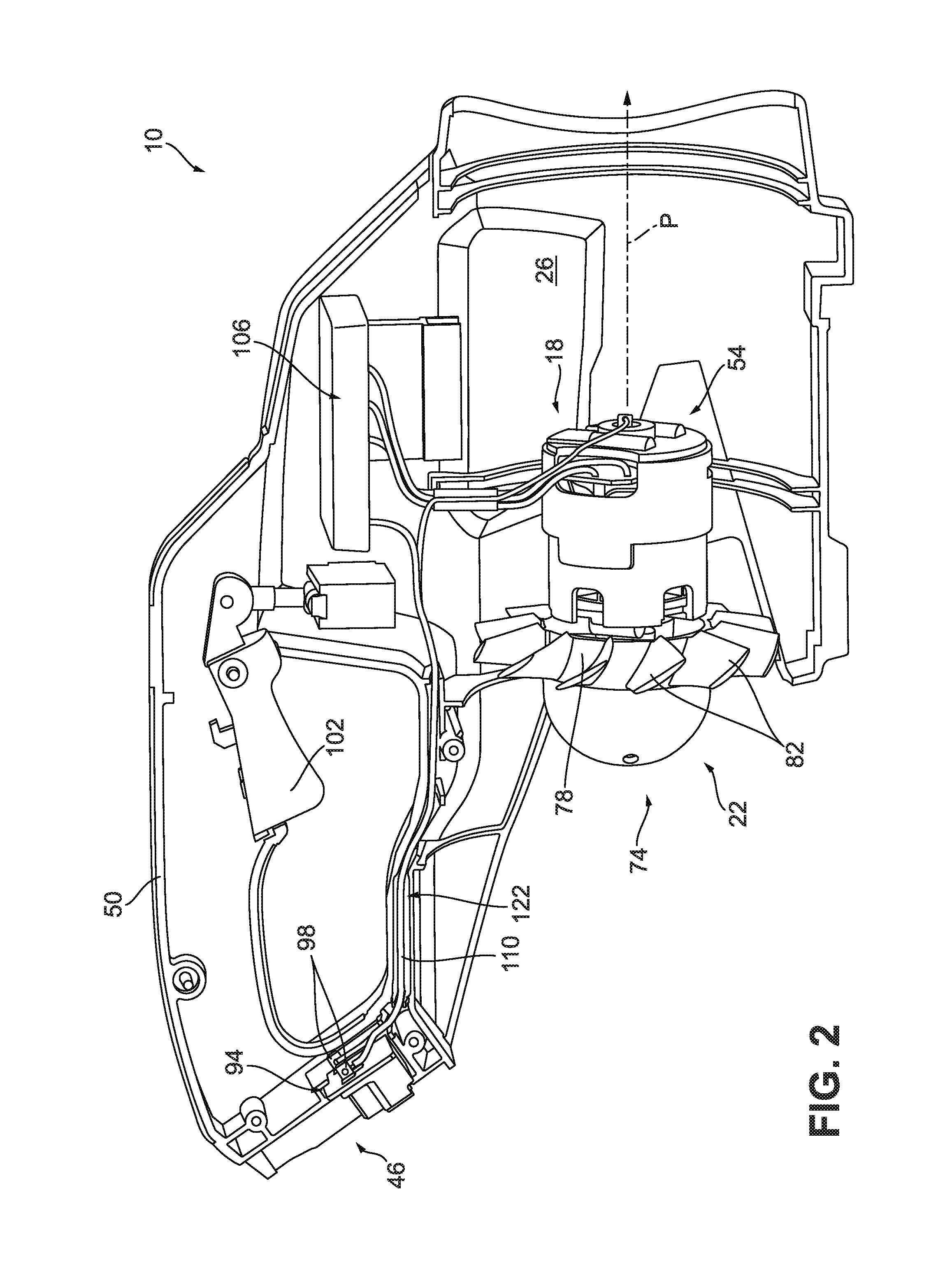
[0008] FIG. 2 is a side view of a portion of the blower of FIG. 1, with portions removed.
[0009] FIG. 3 is an enlarged view of a portion of the blower shown in FIG. 2.
[0010] FIG. 4 is an enlarged view of another portion of the blower shown in FIG. 2.
[0011] FIG. 5 is an enlarged view of another portion of the blower shown in FIG. 2.
[0012] FIG. 6 is a perspective view of electrostatic discharge dissipation structure of the blower.
[0013] FIGS. 7A-7B are perspective views of the conductive interface of the structure shown in FIG. 6.
[0014] FIG. 8 is a perspective view of a terminal connection of the structure shown in FIG. 6.
[0015] FIG. 9 is a perspective view of a portion of a motor assembly.
[0016] FIG. 10 is a perspective view of a portion of an electric tool, such as a blower.
[0017] FIG. 11 is a side view of a portion of the blower shown in FIG. 10.
DETAILED DESCRIPTION
[0018] Before any independent embodiments of the invention are explained in detail, it is to be understood that the invention is not limited in its application to the details of construction and the arrangement of components set forth in the following description or illustrated in the following drawings. The invention is capable of other independent embodiments and of being practiced or of being carried out in various ways. Also, it is to be understood that the phraseology and terminology used herein is for the purpose of description and should not be regarded as limiting.
[0019] Use of "including" and "comprising" and variations thereof as used herein is meant to encompass the items listed thereafter and equivalents thereof as well as additional items. Use of "consisting of" and variations thereof as used herein is meant to encompass only the items listed thereafter and equivalents thereof. Unless specified or limited otherwise, the terms "mounted," "connected," "supported," and "coupled" and variations thereof are used broadly and encompass both direct and indirect mountings, connections, supports, and couplings.
[0020] Relative terminology, such as, for example, "about", "approximately", "substantially", etc., used in connection with a quantity or condition would be understood by those of ordinary skill to be inclusive of the stated value and has the meaning dictated by the context (for example, the term includes at least the degree of error associated with the measurement of, tolerances (e.g., manufacturing, assembly, use, etc.) associated with the particular value, etc.). Such terminology should also be considered as disclosing the range defined by the absolute values of the two endpoints. For example, the expression "from about 2 to about 4" also discloses the range "from 2 to 4". The relative terminology may refer to plus or minus a percentage (e.g., 1%, 5%, 10% or more) of an indicated value.
[0021] Also, the functionality described herein as being performed by one component may be performed by multiple components in a distributed manner. Likewise, functionality performed by multiple components may be consolidated and performed by a single component. Similarly, a component described as performing particular functionality may also perform additional functionality not described herein. For example, a device or structure that is "configured" in a certain way is configured in at least that way but may also be configured in ways that are not listed.
[0022] Furthermore, some embodiments described herein may include one or more electronic processors configured to perform the described functionality by executing instructions stored in non-transitory, computer-readable medium. Similarly, embodiments described herein may be implemented as non-transitory, computer-readable medium storing instructions executable by one or more electronic processors to perform the described functionality. As used in the present application, "non-transitory computer-readable medium" comprises all computer-readable media but does not consist of a transitory, propagating signal. Accordingly, non-transitory computer-readable medium may include, for example, a hard disk, a CD-ROM, an optical storage device, a magnetic storage device, a ROM (Read Only Memory), a RAM (Random Access Memory), register memory, a processor cache, or any combination thereof.
[0023] Many of the modules and logical structures described are capable of being implemented in software executed by a microprocessor or a similar device or of being implemented in hardware using a variety of components including, for example, application specific integrated circuits ("ASICs"). Terms like "controller" and "module" may include or refer to both hardware and/or software. Capitalized terms conform to common practices and help correlate the description with the coding examples, equations, and/or drawings. However, no specific meaning is implied or should be inferred simply due to the use of capitalization. Thus, the claims should not be limited to the specific examples or terminology or to any specific hardware or software implementation or combination of software or hardware.
[0024] FIGS. 1-5 illustrate an electric tool, such as a blower 10, including a housing assembly 14, a power unit 18, a blower fan assembly 22 driven by the power unit 18, and electrostatic discharge dissipation structure 26. During operation, electrostatic charge builds up in the blower 10, and the structure 26 is operable to dissipate this charge to inhibit damage to components of the blower 10 (e.g., electronic components), unwanted discharges to objects touching the blower 10, etc.
[0025] The housing assembly 14 includes a power unit support portion 30 (see FIGS. 10-11) and a duct member 34 (see FIG. 1) defining a flow path P to an outlet 38 from a housing inlet 42. The housing assembly 14 provides a power source connection portion 46 and a handle 50.
[0026] The power unit 18 includes a motor assembly 54 supported by the support portion 30 (e.g., a tubular member with fixed stator blades) in the flow path P. The motor assembly 54 includes a stator 58 supported by the support portion 30 and a rotor 62 supported by bearings 66. A drive shaft 70 is connected to the rotor 62. The fan assembly 22 includes a fan 74 with a hub 78 connected to the drive shaft 70 and blades 82 extending from the hub 78. The fan 74 is driven by the motor assembly 54 to create an air flow through the flow path P.
[0027] The motor assembly 54 is powered by a power source. In the illustrated construction, the power source includes a battery pack 86 supportable on the connection portion 46. The battery pack 86 includes a pack housing 90 mechanically connected to the connection portion 46, one or more battery cells (not shown), and a battery terminal assembly (not shown). In other constructions (not shown), the power source may include a different power source (e.g., an AC power source).
[0028] An electrical circuit selectively connects the power source to the motor assembly 54. The circuit includes a terminal assembly 94 electrically connectable to the battery terminal assembly. The terminal assembly 94 includes at least power terminals 98 (e.g., positive and negative terminals). A switch assembly 102 (e.g., a user-actuated trigger supported on the handle 50) and a controller 106 cooperate to control operation of the blower 10 (e.g., supply of power to the motor assembly 54). The circuit includes a number of wires 110 electrically connecting the components.
[0029] The electrostatic discharge dissipation structure 26 generally electrically connects a rotating portion of the power unit 18 to ground. In the illustrated construction, the structure 26 includes a conductive interface 114 (e.g., a washer, a plate, etc.) in electrical contact with the rotor 62 (through a bearing 66) and an electrical conductor (e.g., a wire 118) electrically connected between the conductive interface 114 and the terminal assembly 94 (e.g., to the negative power terminal 98).
[0030] As shown in FIGS. 7A-7B, the conductive interface 114 includes an annular portion (e.g., extending about a full circumference (as illustrated), a portion of the circumference, etc.) engaging the bearing 66 (see FIG. 4) and a tab projecting from the annular portion. The wire 118 is connected to the tab.
[0031] The housing assembly 14 defines a wire path 122 for the wire 118 and at least some of the wires 110. The path 122 includes opposing retainer members 126 to retain the wires 118, 110 on the path 122. The path 122 is between the handle portion of the housing assembly 14 and the support portion 30.
[0032] In operation, the user holds the handle 50 and engages the switch assembly 102 to power the motor assembly 54 to drive the fan 74. Operation of the fan 74 generates a high velocity air flow and may cause electrostatic discharge to build up in the blower 10. The structure 26 dissipates the built-up charge to avoid unwanted discharges (e.g., to the electronics, to objects contacting the blower 10, etc.).
[0033] Although aspects of the invention have been described in detail with reference to certain preferred constructions, variations and modifications exist within the scope and spirit of one or more independent aspects of the invention as described.
[0034] One or more independent features and/or independent advantages of the invention may be set forth in the following claims:
* * * * *
D00000
D00001
D00002
D00003
D00004
D00005
D00006
D00007
D00008
D00009
D00010
D00011
D00012

XML
uspto.report is an independent third-party trademark research tool that is not affiliated, endorsed, or sponsored by the United States Patent and Trademark Office (USPTO) or any other governmental organization. The information provided by uspto.report is based on publicly available data at the time of writing and is intended for informational purposes only.
While we strive to provide accurate and up-to-date information, we do not guarantee the accuracy, completeness, reliability, or suitability of the information displayed on this site. The use of this site is at your own risk. Any reliance you place on such information is therefore strictly at your own risk.
All official trademark data, including owner information, should be verified by visiting the official USPTO website at www.uspto.gov. This site is not intended to replace professional legal advice and should not be used as a substitute for consulting with a legal professional who is knowledgeable about trademark law.