Valve Orientation Device For Timepieces
LOETSCHER; Philippe
U.S. patent application number 16/052746 was filed with the patent office on 2019-03-07 for valve orientation device for timepieces. This patent application is currently assigned to Omega SA. The applicant listed for this patent is Omega SA. Invention is credited to Philippe LOETSCHER.
| Application Number | 20190072904 16/052746 |
| Document ID | / |
| Family ID | 59772480 |
| Filed Date | 2019-03-07 |

| United States Patent Application | 20190072904 |
| Kind Code | A1 |
| LOETSCHER; Philippe | March 7, 2019 |
VALVE ORIENTATION DEVICE FOR TIMEPIECES
Abstract
An orientable valve including a device for adjusting the angular orientation of the valve head with respect to the watch case, wherein the device for adjusting the angular orientation of the valve head includes a friction ring disposed between the valve head and the upper step, the friction ring rotates integrally with the shaft and is free in translation with respect to the shaft, the friction ring has a cylindrical external friction surface in friction contact with an internal wall of the tube, and wherein the shaft includes, in its distal portion, a device for actuating the latter in rotation making it possible to pivot the valve to adjust the angular orientation of the valve head.
| Inventors: | LOETSCHER; Philippe; (Evilard, CH) | ||||||||||
| Applicant: |
|
||||||||||
|---|---|---|---|---|---|---|---|---|---|---|---|
| Assignee: | Omega SA Biel/Bienne CH |
||||||||||
| Family ID: | 59772480 | ||||||||||
| Appl. No.: | 16/052746 | ||||||||||
| Filed: | August 2, 2018 |
| Current U.S. Class: | 1/1 |
| Current CPC Class: | G04B 37/084 20130101; G04B 37/08 20130101; F16K 17/04 20130101 |
| International Class: | G04B 37/08 20060101 G04B037/08; F16K 17/04 20060101 F16K017/04 |
Foreign Application Data
| Date | Code | Application Number |
|---|---|---|
| Sep 1, 2017 | EP | 17189111.2 |
Claims
1. An orientable valve device comprising: a valve provided at a proximal end with a valve head integral with a central shaft terminating in a distal end, the front face of said head comprising a logo or a trademark, a tube intended to be assembled to a watch case, the shaft being arranged to be able to move in translation along its longitudinal axis in said tube, the tube comprising an inner shoulder defining an upper step and a lower step and delimiting a first upper space inside which is housed the valve head and a second lower space defining a passage connected to the interior of the watch case and into which extends one portion of the central shaft, a sealing gasket surrounding the central shaft to ensure the seal between the shaft and an internal wall of the tube, a return spring surrounding the shaft portion housed inside the passage and extending between the lower step and a stop member arranged at the distal end of the valve shaft so as to hold the valve head in abutment against the gasket, and a device for adjusting the angular orientation of the valve head with respect to the watch case, wherein said device for adjusting the angular orientation of the valve head includes a friction ring arranged concentrically around the central shaft, between the valve head and the stop member, wherein the friction ring rotates integrally with the shaft and is free in translation with respect to the shaft, wherein the friction ring includes an external friction surface in friction contact with an internal wall of the tube, and wherein said device for adjusting the angular orientation of the valve head includes means for rotational actuation of the latter making it possible to pivot the valve against the frictional forces generated by the friction ring in order to adjust the angular orientation of the valve head.
2. The valve device according to claim 1, wherein the actuating means are arranged in the distal portion of the central shaft.
3. The valve device according to claim 2, wherein the actuating means also form the stop member for the return spring.
4. The valve device according to claim 2, wherein the actuating means is a nut.
5. The valve device according to claim 1, wherein the actuating means includes a slot.
6. The valve device according to claim 5, wherein the slot is arranged in the distal end of the shaft or in the nut.
7. The valve device according to claim 1, wherein the friction torque generated by the friction ring inside the tube is greater than the screw torque of the nut on the shaft.
8. The valve device according to claim 1, wherein the friction ring is arranged between the sealing gasket and the upper step.
9. The valve device according to claim 1, wherein the friction ring includes an opening of polygonal shape and wherein the shaft has a polygonal cross section complementary to said opening to make the shaft integral in rotation with the ring.
10. The valve device according to claim 1, wherein the friction ring is disposed in said first upper space.
11. The valve device according to claim 1, wherein the friction ring is disposed in said second lower space.
12. The valve device according to claim 1, wherein the sealing gasket is arranged between the valve head and the upper step of the tube.
13. A watch case comprising an orientable valve device including: a valve provided at a proximal end with a valve head integral with a central shaft terminating in a distal end, the front face of said head comprising a logo or a trademark, a tube intended to be assembled to a watch case, the shaft being arranged to be able to move in translation along its longitudinal axis in said tube, the tube comprising an inner shoulder defining an upper step and a lower step and delimiting a first upper space inside which is housed the valve head and a second lower space defining a passage connected to the interior of the watch case and into which extends one portion of the central shaft, a sealing gasket surrounding the central shaft to ensure the seal between the shaft and an internal wall of the tube, a return spring surrounding the shaft portion housed inside the passage and extending between the lower step and a stop member arranged at the distal end of the valve shaft so as to hold the valve head in abutment against the gasket, and a device for adjusting the angular orientation of the valve head with respect to the watch case, wherein said device for adjusting the angular orientation of the valve head includes a friction ring arranged concentrically around the central shaft, between the valve head and the stop member, wherein the friction ring rotates integrally with the shaft and is free in translation with respect to the shaft, wherein the friction ring includes an external friction surface in friction contact with an internal wall of the tube, and wherein said device for adjusting the angular orientation of the valve head includes means for rotational actuation of the latter making it possible to pivot the valve against the frictional forces generated by the friction ring in order to adjust the angular orientation of the valve head.
Description
[0001] This application claims priority from European Patent Application No. 17189111.2 filed on Sep. 1, 2017; the entire disclosure of which is incorporated herein by reference
[0002] The present invention concerns a device for adjusting the orientation of a valve of a valve device screwed or pressed into a watch case and more specifically for automatic helium escape valve devices wherein the valve comprises a motif or a logo on its end face and wherein the motif can be oriented as desired.
[0003] Helium escape valve devices, also known as helium release valves, are present in certain dive watches for removing helium that has penetrated the watch case during saturation dives where divers inhale a gas mixture containing helium and oxygen. This allows them to stay inside a diving bell or underwater habitat for several days. During this time period, helium may penetrate the watch. In the absence of such a valve, internal overpressure caused by helium that has seeped in may, during the decompression phase, cause damage to the watch, such as, for example, loss of the crystal which may pop out or break.
[0004] An automatic valve device includes a valve having a cylindrical head integral with a central shaft arranged to be able to move in translation along its longitudinal axis in a tube screwed or pressed into a lateral portion of the watch case. The tube includes an internal shoulder defining an upper step and a lower step. The internal shoulder delimits a first upper space inside which is housed the valve head and a second lower space defining a passage connected to the interior of the case and into which extends one portion of the central shaft. An annular sealing gasket is disposed around the central shaft between the valve head and the upper step of the tube. The head is held in abutment against the gasket by means of a return spring surrounding the shaft portion housed inside the passage and extending between the lower step and a nut screwed onto the free end of the valve shaft. Thus, the gasket is able to rise up against the return force of the spring when the pressure inside the case becomes higher than the pressure outside. Gas is then evacuated from the interior of the watch to the exterior.
[0005] The manufacture and assembly of these valve devices, which are screwed or pressed into watch cases, are well known. However, methods for assembling such valve devices are ill suited to the devices when the valve bears an inscription or a motif, for example a logo, a trademark or similar sign, on its end face. Indeed, known assembly methods do not generally allow the valve head to be moved into a determined precise angular position with respect to the case when the valve device is assembled by screwing or pressing the tube into the watch case. This therefore detracts from the aesthetics of the watch when an inscription is affixed to the end face of the valve head. This situation is evidently unacceptable when these valve devices are fitted to high quality and luxury products.
[0006] It is an object of the present invention to overcome the drawbacks of the aforementioned prior art by providing a screw-in or press-in valve device, in particular an automatic helium escape valve device of simple and economical construction and wherein the valve head includes on its end face a motif, such as a logo or a trademark, and wherein the position of the logo or the trademark affixed to the end face of said head can easily be adjusted into a determined precise angular orientation or position.
[0007] To this end, the invention concerns an orientable valve device including:
[0008] a valve provided at a proximal end with a valve head integral with a central shaft terminating in a distal end, the front face of said head comprising a logo or a trademark,
[0009] a tube intended to be assembled to a watch case, for example screwed-in or pressed-in, the shaft being arranged to be able to move in translation along its longitudinal axis in said tube, the tube comprising an inner shoulder defining an upper step and a lower step and delimiting a first upper space inside which is housed the valve head and a second lower space defining a passage connected to the interior of the watch case and into which extends one portion of the central shaft,
[0010] a sealing gasket surrounding the central shaft to ensure the seal between the central shaft and an internal wall of the tube, and preferably disposed between the valve head and the upper step of the tube,
[0011] a return spring surrounding the shaft portion housed inside the passage and extending between the lower step and a stop member arranged at the distal end of the valve shaft so as to hold the valve head in abutment against the gasket, and
[0012] a device for adjusting the angular orientation of the valve head with respect to the watch case, characterized in that
[0013] said device for adjusting the angular orientation of the valve head includes a friction ring arranged concentrically around the central shaft, between the valve head and the stop member,
[0014] in that the friction ring rotates integrally with the shaft and is free in translation with respect to the shaft,
[0015] in that the friction ring includes an external, for example cylindrical friction surface in friction contact with an inner wall of the tube,
[0016] and in that said device for adjusting the angular orientation of the valve head includes means for rotational actuation of the latter making it possible to pivot the valve against the frictional forces generated by the friction ring in order to adjust the angular orientation of the valve head, said actuating means being preferably arranged in the distal portion of the shaft.
[0017] According to other advantageous aspects of the invention: [0018] the actuating means also form the stop member for the return spring. [0019] the actuating means is a nut. [0020] the actuating means includes a slot, [0021] the slot is arranged in the distal end of the shaft or in the nut. [0022] the friction torque produced by the friction ring inside the tube is greater than the screw torque of the nut on the shaft. [0023] the friction ring is arranged between the sealing gasket and the upper step. [0024] the friction ring includes a polygonal opening and the shaft has a polygonal cross section complementary to said opening to make the shaft integral in rotation with the ring. [0025] the stop ring can either be disposed in the first upper space or in the second lower space.
[0026] The invention also concerns a watch case including a valve device as described above.
[0027] Other features and advantages of the present invention will appear more clearly from the following detailed description of a preferred embodiment, given by way of non-limiting example, with reference to the annexed drawings, in which:
[0028] FIG. 1 shows a top view of an orientable valve device, provided with a logo on the external face of the valve head according to the invention.
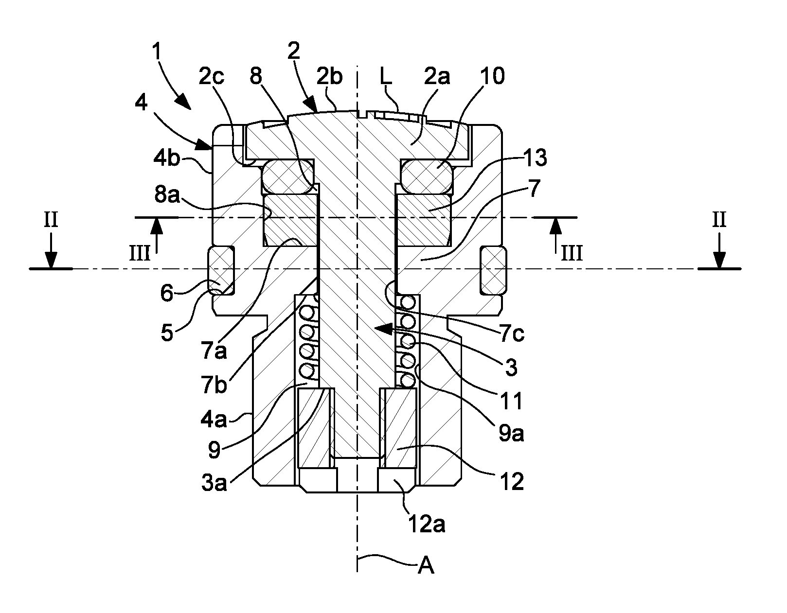
[0029] FIG. 2 shows a cross-sectional view of the orientable valve device according to the invention along the line II-II of FIG. 1.
[0030] FIG. 3 shows a section of the orientable valve device according to the invention, along the line III-III of FIG. 2.
[0031] FIG. 4 shows a section of the orientable valve device according to the invention, along the line IV-IV of FIG. 2.
[0032] FIGS. 1 and 2 represent an automatic valve device designated by the general reference 1 and intended to be mounted by being pressed or screwed into the side wall of a watch case middle (not represented).
[0033] In FIG. 1, which is a top view of valve device 1, the logo L "He" can be seen, arranged on the external face of a valve 2, inside which is housed the orientation adjustment device described below with reference to FIGS. 2 to 4. For aesthetic reasons, this logo L is adjusted in a perfectly horizontal position, preferably corresponding to the plane of the middle part of the watch case in which the valve is mounted.
[0034] Valve device 1 includes a valve 2 provided with a valve head 2a integral with a central shaft 3. The front face 2b of head 2a includes logo L.
[0035] Device 1 further includes a tube 4 intended to be pressed via its lower portion 4a into an opening in the watch case middle. Tube 4 has an upper portion 4b of larger diameter than lower portion 4a. In the lower area of its upper portion, tube 4 has an annular groove 5 inside which is housed an O-ring joint 6 which seals the tube with respect to the case middle.
[0036] Depending upon the embodiment, tube 4 can either end in an upper portion that protrudes from case middle 4 or be embedded in the case middle.
[0037] Tube 4 has an internal shoulder 7 defining an upper step 7a and a lower step 7b and an opening 7c of reduced diameter. Internal shoulder 7 also delimits a first upper space 8, inside which is housed valve head 2, and a second lower space defining a passage 9, connected to the interior of the watch case.
[0038] Central shaft 3 is arranged inside tube 4 so as to be able to move in translation along its longitudinal axis A and to rotate freely in opening 7c.
[0039] The device further includes an annular sealing gasket 10 surrounding the central shaft and disposed beneath head 2a between the latter and upper step 7a.
[0040] It is also seen that device 1 further comprises a helical return spring 11 which surrounds the central portion of shaft 3 extending into or housed inside passage 8. Spring 11 is mounted compressed between lower step 7b and a stop member 12, integral in translation with central shaft 3 and arranged at the distal end of central shaft 3.
[0041] In the illustrated example, stop member 12 is a nut screwed onto the distal portion of the shaft tight against a shoulder 3a of the latter. Head 2a is thus held in abutment by its back face 2c against annular sealing gasket 10 by means of return spring 11.
[0042] The device further includes a device for adjusting the angular orientation of valve head 2 with respect to the watch case. The adjustment device includes a friction ring 13 disposed between valve head 2a and upper step 7a and, in the illustrated example, the friction ring is more specifically disposed between annular gasket 10 and upper step 7a. Friction ring 13 has a cylindrical external surface 13a whose diameter is an interference fit on inner wall 8a of upper space 8 of tube 4, and therefore in friction contact with said wall 8a.
[0043] It is evident that, in a variant, friction ring 13 could be disposed between annular gasket 10 and back face 2c of the valve head or even, in another variant, inside lower space 9, for example between the upper end of spring 11 and lower step 7b. In this latter case, the cylindrical external surface 13a of friction ring 13 has a diameter that is an interference fit on inner wall 9a of lower space 9 of tube 4 and is thus in friction contact with said wall 9a.
[0044] As seen in FIG. 3, friction ring 13 includes a central opening 13b of polygonal shape, in this case hexagonal, and central shaft 3 has a polygonal cross section complementary to opening 13b to make shaft 3 integral in rotation with ring 13 while allowing the shaft to move freely in translation in opening 13b.
[0045] It will be noted that nut 12 includes, in its distal face, a slot 12a intended to cooperate with the end of a tool in order to be screwed onto the distal portion of the shaft tight against shoulder 3a. Once screwed tight against shoulder 3a, since the friction fit of friction ring 13 on inner wall 8 is chosen so that the friction torque produced by the friction ring inside the tube is greater than the screw torque of nut 12 on central shaft 3, nut 12 thus acts as a means of actuating valve 2 in rotation, which makes it possible to pivot the valve and thereby adjust the angular orientation of valve head 2 into a determined angular position. It will be noted in this regard that the surface of internal wall 8a and/or cylindrical external surface 13a of the ring can be textured to adjust the appropriate friction torque.
[0046] It will be noted that, in this embodiment, nut 12 has a dual function, namely it forms both the stop member for return spring 11 and the means for actuating valve 2 in order to pivot and angularly orient said valve. However, in variant embodiments that are not represented, it is possible, without departing from the scope of the invention, to envisage arranging, for example, an elastic ring inserted into an annular groove of the distal portion of central shaft 3 as the stop member and a slot arranged directly in the fact of the distal end of central shaft 3, as the valve actuating means.
[0047] The method for mounting the valve device and orienting the valve is as follows. The completely assembled valve device 1, with nut 12 screwed tight against shoulder 3a of the shaft, is pressed or screwed into an opening in the watch case middle. Once the device is pressed or screwed in, with tube 4 thereby immobilised in the case middle, nut 12 can then be screwed on by means of a tool inserted into slot 12a from inside the case middle and can drive the valve head in rotation. The valve head in turn thereby drives friction ring 13, via the polygon connection between opening 13a and the cross-section of central shaft 3, into the desired angular position. Ring 13 turns in tube 4 against the retaining frictional force between external surface 13a of friction ring 13 and internal wall 8a of the upper space of the tube, which is lower than the torque applied by the tool to the nut when nut 12 is tight against shoulder 3a.
[0048] According to an alternative embodiment, it is possible to envisage arranging the means for rotational actuation in the proximal portion of the valve and, in particular, front face 2b of valve head 2a could be arranged to include housings for receiving the ends of an operating tool. Alternatively, it is possible to envisage the valve head protruding slightly with respect to the external end face of the tube and having a non-circular, for example hexagonal, side surface, capable of being gripped by a suitable tool.
* * * * *
D00000
D00001
XML
uspto.report is an independent third-party trademark research tool that is not affiliated, endorsed, or sponsored by the United States Patent and Trademark Office (USPTO) or any other governmental organization. The information provided by uspto.report is based on publicly available data at the time of writing and is intended for informational purposes only.
While we strive to provide accurate and up-to-date information, we do not guarantee the accuracy, completeness, reliability, or suitability of the information displayed on this site. The use of this site is at your own risk. Any reliance you place on such information is therefore strictly at your own risk.
All official trademark data, including owner information, should be verified by visiting the official USPTO website at www.uspto.gov. This site is not intended to replace professional legal advice and should not be used as a substitute for consulting with a legal professional who is knowledgeable about trademark law.