Semiautomatic Firearm
VERNEY-CARRON; Pierre Jean Marie
U.S. patent application number 16/084561 was filed with the patent office on 2019-03-07 for semiautomatic firearm. This patent application is currently assigned to Verney-Carron S.A.. The applicant listed for this patent is Verney-Carron S.A.. Invention is credited to Pierre Jean Marie VERNEY-CARRON.
| Application Number | 20190072349 16/084561 |
| Document ID | / |
| Family ID | 57184522 |
| Filed Date | 2019-03-07 |


| United States Patent Application | 20190072349 |
| Kind Code | A1 |
| VERNEY-CARRON; Pierre Jean Marie | March 7, 2019 |
SEMIAUTOMATIC FIREARM
Abstract
The semiautomatic firearm comprises: means capable of recovering energy resulting from pressure exerted when firing an ammunition (7) to move a movable assembly (4) against a return spring (10), wherein the firearm comprises a stopper, a latch and a striker cooperating with a hammer (5) controlled by a trigger (6), locking means for locking the movable assembly in a compressed position of the return spring at a rear position of movement of the movable assembly, after each shot, an unlocking assembly (12) that is manually actionable and able to act on the locking means for releasing the movable assembly (4) and allowing the assisted return of said movable assembly (4) in order for reloading.
| Inventors: | VERNEY-CARRON; Pierre Jean Marie; (Rivas, FR) | ||||||||||
| Applicant: |
|
||||||||||
|---|---|---|---|---|---|---|---|---|---|---|---|
| Assignee: | Verney-Carron S.A. Saint Etienne FR |
||||||||||
| Family ID: | 57184522 | ||||||||||
| Appl. No.: | 16/084561 | ||||||||||
| Filed: | March 7, 2017 | ||||||||||
| PCT Filed: | March 7, 2017 | ||||||||||
| PCT NO: | PCT/FR2017/050501 | ||||||||||
| 371 Date: | September 13, 2018 |
| Current U.S. Class: | 1/1 |
| Current CPC Class: | F41A 17/80 20130101; F41A 17/76 20130101; F41A 17/74 20130101; F41A 17/42 20130101; F41A 17/78 20130101 |
| International Class: | F41A 17/42 20060101 F41A017/42; F41A 17/78 20060101 F41A017/78; F41A 17/80 20060101 F41A017/80 |
Foreign Application Data
| Date | Code | Application Number |
|---|---|---|
| Mar 14, 2016 | FR | 1652098 |
Claims
1. A semiautomatic firearm comprising: means capable of recovering energy resulting from pressure exerted when firing an ammunition (7) to move a movable assembly (4) against a return spring (10), wherein the firearm comprises a stopper, a latch and a striker cooperating with a hammer (5) controlled by a trigger (6), characterized in that the firearm comprises: locking means, made up by the hammer (5), for locking the movable assembly in a compressed position of the return spring at a rear position of movement of the movable assembly, after each shot, a manually actuatable unlocking assembly (12) capable of acting on the locking means (5) to release the movable assembly to allow the assisted return of said movable assembly to perform an ammunition reloading.
2. A semiautomatic firearm comprising: means capable of recovering energy resulting from pressure exerted when firing an ammunition (7) to move a movable assembly (4) against a return spring (10), wherein the firearm comprises a stopper, a latch and a striker cooperating with a hammer (5) controlled by a trigger (6), characterized in that the firearm comprises: locking means, made up by a pivoting fork (11), for locking the movable assembly in a compressed position of the return spring at a rear position of movement of the movable assembly, after each shot, a manually actuatable unlocking assembly (12) capable of acting on the locking means (11) to release the movable assembly to allow the assisted return of said movable assembly to perform an ammunition reloading.
3. The firearm according to claim 1, characterized in that the unlocking assembly (12), when manually actuated, cooperates with two parts (15) and (15a), able to neutralize the striker of the firearm, by making the hammer (5) inoperative.
4. The firearm according to claim 3, characterized in that the two parts are made up by an unlocking finger (15) and an unlocking notch (15a).
5. The firearm according to claim 4, characterized in that the unlocking notch (15a) has a beak cooperating with a boss on the hammer (5) to make the hammer drop when the unlocking assembly is manually actuated.
6. The firearm according to claim 4, characterized in that the unlocking assembly (12) is securely connected with the unlocking finger (15), by means of a pivoting pin (13) that has the unlocking assembly.
7. The firearm according to claim 6, characterized in that the pivoting pin (13) has a polygonal male step cooperating with a female cavity having a complementary shape, formed in a thickness of the unlocking finger (15).
8. The firearm according to claim 1, characterized in that the unlocking assembly (12), when manually actuated, cooperates with one part (15) able to neutralize the striker of the firearm by disengaging the trigger (6).
9. The firearm according to claim 8, characterized in that the unlocking assembly (12) is made up of an articulated lever (12) mounted pivotably relative to an articulation pin (13) and having an operating finger cooperating with an opening in order to be accessible from outside the firearm.
10. The firearm according to claim 2, characterized in that the unlocking assembly (12), when manually actuated, cooperates with two parts (15) and (15a), able to neutralize the striker of the firearm, by making the hammer (5) inoperative.
11. The firearm according to claim 2, characterized in that the unlocking assembly (12), when manually actuated, cooperates with one part (15) able to neutralize the striker of the firearm by disengaging the trigger (6).
Description
[0001] The invention belongs to the technical field of firearms and more specifically relates to a semiautomatic firearm of any caliber.
[0002] As is fully known to the person skilled in the art, this type of firearm comprises a movable assembly mounted in a breech housing. This movable assembly comprises, essentially, a stopper, a latch and a striker, which can be struck by the effect of swinging a hammer controlled by a trigger, against a return spring.
[0003] For this type of semiautomatic firearm, arming the striker system is done by moving the movable assembly, which can be done by recovery of energy released by a fired ammunition. This recovery can be done by means of an inertial system, a system taking gas from the barrel, or by recoil of the barrel.
[0004] Because of the operating principle of a semiautomatic firearm, the cartridge is immediately re-chambered, which can lead to a risk of accidents.
[0005] The goal of the invention is to remedy these disadvantages simply, safely, effectively and rationally.
[0006] The problem that the invention proposes to resolve is proposing an additional safety able to create a time delay around chambering. Rechambering becomes a manual and intentional action.
[0007] To resolve such a problem, a semiautomatic firearm was designed and developed comprising means capable of recovering energy resulting from pressure exerted when firing an ammunition to move a movable assembly against a return spring and comprising a stopper, a latch and a striker cooperating with a hammer controlled by a trigger.
[0008] According to the invention, in consideration of the problem to be resolved, the semiautomatic type of firearm comprises: [0009] locking means for locking the movable assembly in a compressed position of the return spring at a rear position of movement of the movable assembly, after each shot, [0010] a manually actuatable unlocking assembly capable of acting on the locking means to release the movable assembly to allow the assisted return of said movable assembly to perform an ammunition reloading.
[0011] In a first advantageous embodiment of the invention, the locking means are made up by the hammer, which cooperates with the movable assembly to lock the movable assembly at the rear position of movement.
[0012] It follows from these features that the invention acts on a key part, which is the hammer.
[0013] In this first embodiment, when the unlocking assembly is manually actuated, it cooperates with two parts, able to neutralize the striker system of the firearm, by making the hammer inoperative, where said two parts are made up of an unlocking finger and an unlocking notch.
[0014] The unlocking notch has a beak engaging with a boss on the hammer to make it drop when the unlocking assembly is manually actuated.
[0015] The unlocking assembly is securely connected with the unlocking finger, by means of a pivoting pin that said assembly has, where said pivoting pin has a polygonal male step cooperating with a female cavity having a complementary shape, formed in a thickness of the unlocking finger.
[0016] In another embodiment, the locking means are made of a pivoting fork connecting with the movable assembly.
[0017] In this other embodiment, the unlocking assembly cooperates, when it is manually actuated, with a part able to neutralize the striker system of the firearm by disengaging the trigger, where said unlocking assembly is made up of an articulated lever mounted pivotably relative to an articulation pin and having an operating finger cooperating with an opening in order to be accessible from outside the firearm.
[0018] The invention is disclosed below in detail with the help of the figures from the attached drawings, in which:
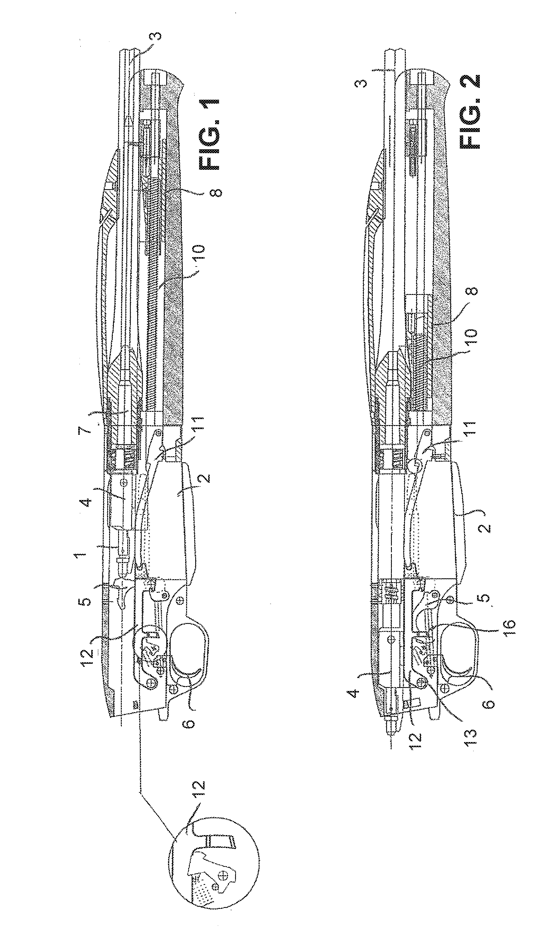
[0019] FIG. 1 is a partial longitudinal section view of an example of a firearm according to the features of the invention shown in phase 1 of firing;
[0020] FIG. 2 is a view corresponding to FIG. 1 shown in phase 2 of locking the movable assembly at a rear position of the movement;
[0021] FIG. 3 is a perspective view of the lower receiver, showing in particular the hammer controlled by the unlocking assembly, corresponding to the advantageous embodiment, according to the invention;
[0022] FIG. 4 is a front view corresponding to FIG. 3;
[0023] FIG. 5 is a side view from FIG. 4;
[0024] FIG. 6 is a top view from FIG. 3;
[0025] FIG. 7 is a longitudinal section view, taken along line A-A from FIG. 5;
[0026] FIG. 8 is a section view, taken along the line B-B from FIG. 6.
[0027] As indicated, the invention applies to any semiautomatic type firearm, whatever the caliber.
[0028] This type of firearm is fully known to the person skilled in the art and can have several embodiments. For the most part, this firearm type has a stock, not shown, a breech housing (1), a magazine (2) and a barrel (3). The breech housing (1) receives a movable assembly (4) essentially comprising a stopper, a latch and a striker, which is struck by the effect of swinging a hammer (5) controlled by a trigger (6).
[0029] Arming of the movable assembly (4) is done by means capable of recovering energy resulting from pressure exerted when firing an ammunition (7). This energy can be recovered either by inertia, by a gas operated system, or even by recoil of the barrel, as is currently used in semiautomatic type firearms. This energy recovery therefore allows the movement of the movable assembly (4) against a return spring (10). Finally, the firearm comprises locking means for locking the movable assembly (4) in a compressed position of the return spring (10) at a rear position of movement of the movable assembly, after each shot.
[0030] The firearm has an unlocking assembly (12) that is manually actionable and able to act on the hammer (5), for releasing the movable assembly (4) and allowing the assisted return of said assembly, in order for reloading. The unlocking assembly is made up of an operating lever (12), accessible from outside the firearm.
[0031] More specifically, the unlocking lever (12) is secured to the hammer (5), which consequently constitutes the locking means by cooperating with two parts (15) and (15a), able to neutralize the striker system of the firearm, consequently making said hammer (5) inoperable.
[0032] As FIG. 7 shows more specifically, these two parts are made up by an unlocking 20 finger (15) and an unlocking notch (15a).
[0033] The unlocking lever (12) is securely connected with the unlocking finger (15) by means of a pivoting pin (13), which said lever (12) has; said pin is inserted transversely, FIG. 8.
[0034] More specifically, this pin (13) has a polygonal male step, for example square-shaped, cooperating with a female cavity having a complementary shape, formed in a thickness of the unlocking finger (15).
[0035] Thus, when one acts on the unlocking lever (12), the unlocking finger (15), which cooperates by supporting with the unlocking notch (15a), acts on said notch, which has a beak cooperating with a boss on the hammer, to make it go down.
[0036] The result of these features is that the locking back of the movable assembly is done directly by the hammer, which constitutes a key part of the firearm.
[0037] In another embodiment, these locking means are made of a pivoting fork (11) connecting with the movable assembly (FIGS. 1 and 2).
[0038] In this embodiment, the unlocking assembly is made up of an articulated lever (12) mounted pivotably relative to an articulation pin (13) and having an operating finger cooperating with an opening in order to be accessible from outside the firearm.
[0039] As with the previous embodiment, to avoid a shunting of the locking at a rear position of the movement of the movable assembly (4) by exerting, for example, a continuous pressure on this lever (12), this lever cooperates, when it is actuated 15 manually, with a part (15) able to neutralize the striker system of the firearm by disengaging the trigger.
[0040] The following is the operation of the firearm:
[0041] After firing the firearm, the firearm is closed, the hammer (5) strikes the movable assembly (strikes the striker) (4) for the discharge of the ammunition (7).
[0042] Under the effect of the pressure exerted by the discharge of the ammunition, the energy is recovered for the movement of the movable assembly (4).
[0043] Under the effect of recovery of the energy, there is an assisted ejection of the ammunition (7). The hammer (5) is rearmed under the effect of the recoil of the movable assembly (4); the hammer spring (16) is compressed. In this position, there is therefore an assisted ejection of the ammunition (7), assisted loading of the hammer (5) spring (16) and assisted loading of the return spring (10).
[0044] After unlocking, the movable assembly (4) is unlocked following pressing on the lever, secured to the hammer (5) or to the fork (11). The result of this is the disengagement of the trigger (6), which consequently blocks the striker system.
[0045] It follows from these features that, in the case of a semiautomatic rifle, the movable assembly is locked by the hammer (5) or the fork (11), which increases the safety by placing a stop at a rear position of the movement of the movable assembly, such that the cartridge is not immediately rechambered. A time delay is obtained before chambering. Rechambering becomes a manual and intentional action.
* * * * *
D00000
D00001
D00002
XML
uspto.report is an independent third-party trademark research tool that is not affiliated, endorsed, or sponsored by the United States Patent and Trademark Office (USPTO) or any other governmental organization. The information provided by uspto.report is based on publicly available data at the time of writing and is intended for informational purposes only.
While we strive to provide accurate and up-to-date information, we do not guarantee the accuracy, completeness, reliability, or suitability of the information displayed on this site. The use of this site is at your own risk. Any reliance you place on such information is therefore strictly at your own risk.
All official trademark data, including owner information, should be verified by visiting the official USPTO website at www.uspto.gov. This site is not intended to replace professional legal advice and should not be used as a substitute for consulting with a legal professional who is knowledgeable about trademark law.