Heat Exchanger
TAKAHASHI; Kazuyuki ; et al.
U.S. patent application number 16/057821 was filed with the patent office on 2019-03-07 for heat exchanger. This patent application is currently assigned to KEIHIN THERMAL TECHNOLOGY CORPORATION. The applicant listed for this patent is KEIHIN THERMAL TECHNOLOGY CORPORATION. Invention is credited to Mana KOBAYASHI, Hiroshi OTSUKI, Kazuyuki TAKAHASHI.
| Application Number | 20190072344 16/057821 |
| Document ID | / |
| Family ID | 65364248 |
| Filed Date | 2019-03-07 |

| United States Patent Application | 20190072344 |
| Kind Code | A1 |
| TAKAHASHI; Kazuyuki ; et al. | March 7, 2019 |
HEAT EXCHANGER
Abstract
A heat exchanger includes exchange tubes formed from an aluminum extrudate and fins made of an aluminum bare material. The wall of each heat exchange tube is composed of a main body portion made of an Al alloy forming the aluminum extrudate, and a covering layer made of an Al--Si--Zn alloy and covering the main body portion. A diffusion layer containing Zn and Si diffused from the Al--Si--Zn alloy is formed in an outer surface layer portion of the main body portion. A low potential portion whose spontaneous potential is the lowest, and a high potential portion whose spontaneous potential is 60 mV or more higher than that of the low potential portion, are present within a range between an outermost surface of the wall and a deepest portion of the diffusion layer such that the low potential portion is located toward the outermost surface of the wall.
| Inventors: | TAKAHASHI; Kazuyuki; (Oyama-shi, JP) ; OTSUKI; Hiroshi; (Oyama-shi, JP) ; KOBAYASHI; Mana; (Oyama-shi, JP) | ||||||||||
| Applicant: |
|
||||||||||
|---|---|---|---|---|---|---|---|---|---|---|---|
| Assignee: | KEIHIN THERMAL TECHNOLOGY
CORPORATION Oyama-shi JP |
||||||||||
| Family ID: | 65364248 | ||||||||||
| Appl. No.: | 16/057821 | ||||||||||
| Filed: | August 8, 2018 |
| Current U.S. Class: | 1/1 |
| Current CPC Class: | F28D 2021/0084 20130101; F28F 2255/16 20130101; F28F 9/0251 20130101; F28F 21/084 20130101; F28D 1/05375 20130101; F28F 19/06 20130101 |
| International Class: | F28F 19/06 20060101 F28F019/06 |
Foreign Application Data
| Date | Code | Application Number |
|---|---|---|
| Sep 5, 2017 | JP | 2017-169933 |
Claims
1. A heat exchanger comprising: a plurality of heat exchange tubes formed from an aluminum extrudate; and fins made of an aluminum bare material, each disposed between adjacent heat exchange tubes, and joined to the corresponding heat exchange tubes by a brazing material, wherein each heat exchange tube has a wall composed of a main body portion made of an Al alloy forming the aluminum extrudate, and a covering layer made of an Al--Si--Zn alloy and covering an outer surface of the main body portion; a diffusion layer in which Zn and Si contained in the Al--Si--Zn alloy forming the covering layer are diffused is formed in an outer surface layer portion of the main body portion of the wall of each heat exchange tube; and a low potential portion whose spontaneous potential is the lowest, and a high potential portion whose spontaneous potential is 60 mV or more higher than that of the low potential portion, are present within a range between an outermost surface of the wall of each heat exchange tube and a deepest portion of the diffusion layer such that the low potential portion is located toward the outermost surface of the wall.
2. The heat exchanger according to claim 1, wherein within the range between the outermost surface of the wall of each heat exchange tube and the deepest portion of the diffusion layer, the spontaneous potential of the wall lowers from the outermost surface of the wall toward the main body portion up to the low potential portion, and the spontaneous potential of the wall increases from the low potential portion toward the main body portion up to the high potential portion.
3. The heat exchanger according to claim 1, wherein the brazing material for joining the heat exchange tubes and the corresponding fins is composed of Al contained in the Al alloy forming the aluminum extrudate, and Si of Si powder caused, before joining, to adhere to surfaces of the heat exchange tubes.
4. The heat exchanger according to claim 1, wherein the Al--Si--Zn alloy serving as the covering layer of each heat exchange tube is composed of Al contained in the Al alloy forming the aluminum extrudate, Si of Si powder caused, before joining, to adhere to the surface of the heat exchange tube, and Zn of Zn powder caused, before joining, to adhere to the surface of the heat exchange tube.
Description
BACKGROUND OF THE INVENTION
[0001] The present invention relates to a heat exchanger. More particularly, the present invention relates to a heat exchanger which is used as a condenser for a car air conditioner mounted on a vehicle such as an automobile.
[0002] In this specification and claims, the term "aluminum" encompasses aluminum alloys in addition to pure aluminum. Also, materials represented by chemical symbols represent pure materials, and the term "Al alloy" means an aluminum alloy.
[0003] In this specification, the term "spontaneous potential" of a material refers to the electrode potential of the material within an acidic (pH: 3) aqueous solution of 5% NaCl with respect to a saturated calomel electrode (S.C.E.), which serves as a reference electrode.
[0004] A heat exchanger having the following structure has been widely known and used as a condenser for a car air conditioner. The heat exchanger has a plurality of flat heat exchange tubes formed from an aluminum extrudate, header tanks, corrugated aluminum fins, and aluminum side plates. The flat heat exchange tubes are disposed at predetermined intervals in their thickness direction such that they have the same longitudinal direction and their width direction coincides with an air-flow direction. The header tanks are disposed at opposite longitudinal ends of the heat exchange tubes such that their longitudinal directions coincide with the direction in which the heat exchange tubes are juxtaposed. Opposite ends of the heat exchange tubes are connected to the corresponding header tanks. Each of the fins is disposed between adjacent heat exchange tubes or on the outer side of the heat exchange tube at each of opposite ends, and is brazed to the corresponding heat exchange tube(s). The side plates are disposed outward of the fins at opposite ends and are brazed to the corresponding fins. Each of the header tanks is composed of a tubular tank body formed of aluminum and closing members formed of aluminum. The tank body is formed by bending, into a tubular shape, an aluminum brazing sheet having a brazing material layer on each of opposite sides thereof and brazing opposite side edges of the sheet which are butted against each other. The tank body has openings at opposite ends thereof. The closing members are brazed to the opposite ends of the tank body so as to close the openings at the opposite ends. The tank body has a plurality of tube insertion holes elongated in the air-flow direction and spaced from one another in the longitudinal direction of the tank body. An end portion of each heat exchange tube is inserted into the corresponding tube insertion hole and is brazed to the tank body.
[0005] The present applicant has proposed a method of manufacturing the above-described heat exchanger (see Japanese Patent Application Laid-Open (kokai) No. 2014-238209). The proposed method includes steps of: preparing heat exchange tubes and fins; adhering Zn powder and flux powder to outer surfaces of the heat exchange tubes; and brazing the heat exchange tubes and the corresponding fins and forming a Zn diffused layer in an outer surface layer portion of each of the heat exchange tubes. Each of the heat exchange tubes has a wall thickness of 200 .mu.m or less and is formed from an aluminum extrudate made of an alloy containing Mn in an amount of 0.2 to 0.3 massa, Cu in an amount of 0.05 mass % or less, and Fe in an amount of 0.2 mass % or less, the balance being Al and unavoidable impurities. Each of the fins is formed from a brazing sheet composed of an aluminum core material, and a coating material formed of an aluminum brazing material and covering the opposite sides of the core material. In the step of adhering Zn powder and flux powder to the outer surfaces of the heat exchange tubes, a dispersing liquid is prepared by mixedly dispersing flux powder, and Zn powder having an average particle size of 3 to 5 .mu.m and a largest particle size of less than 10 .mu.m in a binder. The dispersing liquid is applied to the outer surface of each of the heat exchange tubes, and the liquid component of the dispersing liquid is vaporized so as to adhere the Zn powder and the flux powder to the outer surface of each heat exchange tube such that the Zn powder adhesion amount becomes 1 to 3 g/m.sup.2, the flux powder adhesion amount becomes 15 g/m.sup.2 or less, and the ratio of the flux powder adhesion amount to the Zn powder adhesion amount (the flux powder adhesion amount/the Zn powder adhesion amount) becomes 1 or higher. In the step of brazing the heat exchange tubes and the corresponding fins, the heat exchange tubes and the fins in an assembled condition are heated so as to braze the heat exchange tubes and the corresponding fins through utilization of the flux powder adhering to the outer surfaces of the heat exchange tubes and the coating material of the fins and to melt the Zn powder adhering to the outer surfaces of the heat exchange tubes for diffusing Zn in outer surface layer portions of the heat exchange tubes so as to form Zn diffused layers in the respective outer surface layer portions of the heat exchange tubes.
[0006] In manufacture of the heat exchanger by the method described in the publication, the heat exchange tubes and the corresponding fins are joined by a brazing material melted out from the coating material of the brazing sheet for forming the fins.
[0007] A conceivable method for further enhancing the corrosion resistance of the fins in the heat exchanger manufactured by the method described in the publication is to use fins made of an aluminum bare material in place of the fins formed from an aluminum brazing sheet. In this case, the described method may be modified such that, in addition to the Zn powder, Si powder is caused to adhere to the outer surfaces of the heat exchange tubes, and the heat exchange tubes and the corresponding fins are joined by a brazing material composed of Al contained in the Al alloy forming the aluminum extrudate from which the heat exchange tubes are formed, and Si of the Si powder caused, before joining, to adhere to the surfaces of the heat exchange tubes.
[0008] However, in the heat exchanger manufactured by such a method, the corrosion resistance of the heat exchange tubes may become insufficient.
SUMMARY OF THE INVENTION
[0009] An object of the present invention is to solve the above-described problem and to provide a heat exchanger in which heat exchange tubes exhibit excellent corrosion resistance.
[0010] A heat exchanger according to the present invention comprises a plurality of heat exchange tubes formed from an aluminum extrudate and fins made of an aluminum bare material, each disposed between adjacent heat exchange tubes, and joined to the corresponding heat exchange tubes by a brazing material. Each heat exchange tube has a wall composed of a main body portion made of an Al alloy forming the aluminum extrudate, and a covering layer made of an Al--Si--Zn alloy and covering an outer surface of the main body portion. A diffusion layer in which Zn and Si contained in the Al--Si--Zn alloy forming the covering layer are diffused is formed in an outer surface layer portion of the main body portion of the wall of each heat exchange tube. A low potential portion whose spontaneous potential is the lowest, and a high potential portion whose spontaneous potential is 60 mV or more higher than that of the low potential portion, are present within a range between an outermost surface of the wall of each heat exchange tube and a deepest portion of the diffusion layer such that the low potential portion is located toward the outermost surface of the wall.
BRIEF DESCRIPTION OF THE DRAWINGS
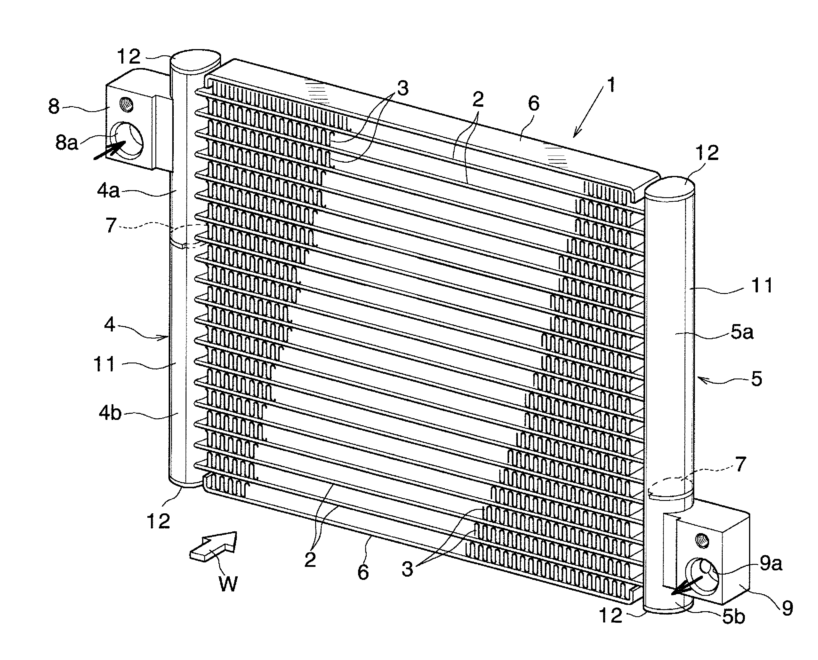
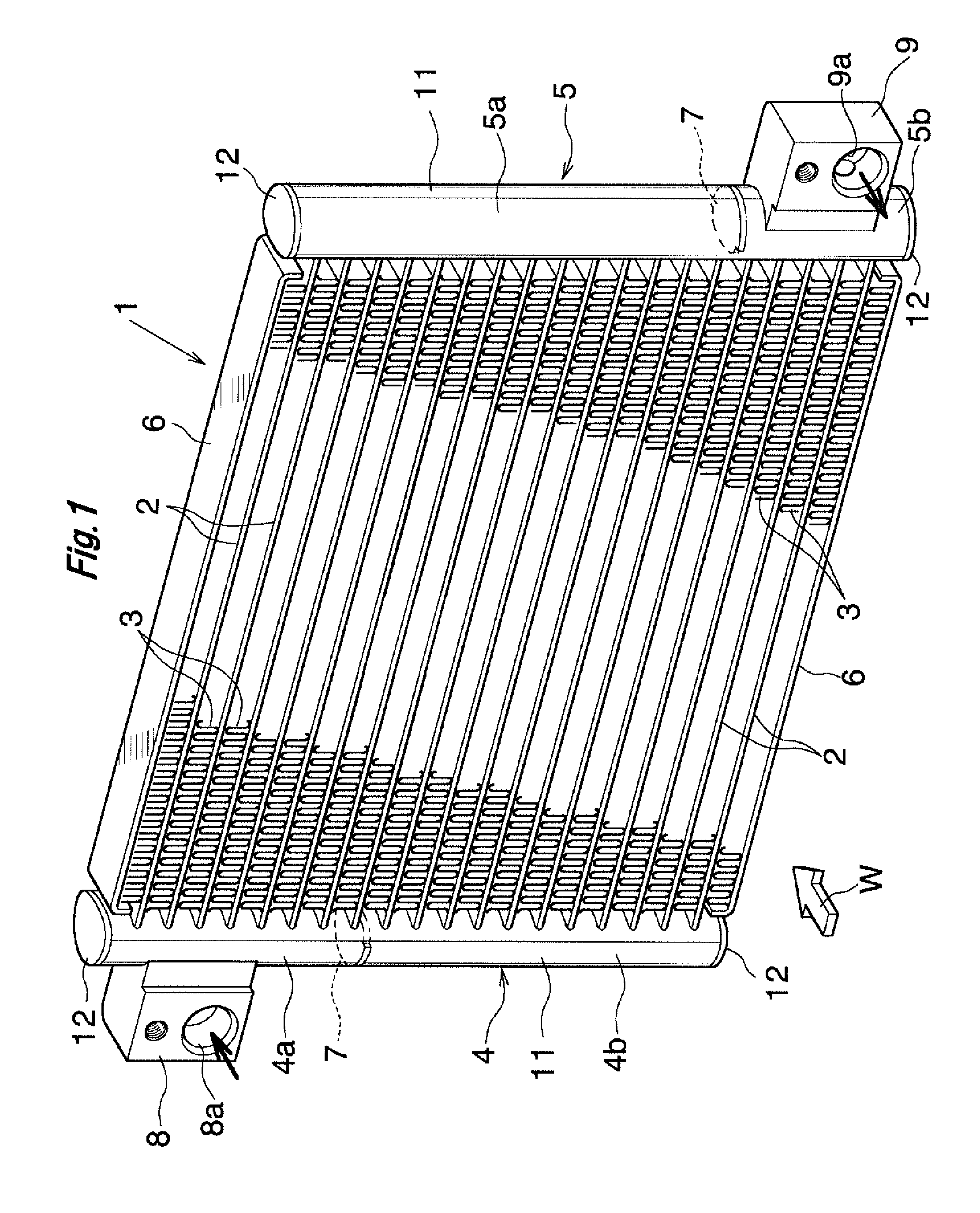
[0011] FIG. 1 is a perspective view showing the overall structure of a condenser for a car air conditioner to which a heat exchanger according to the present invention is applied;
[0012] FIG. 2 is an enlarged sectional view partially showing the wall of a heat exchange tube of the condenser of FIG. 1; and
[0013] FIG. 3 is a graph showing spontaneous potentials at different depths from the wall outermost surface of a single heat exchange tube to which a fin is brazed in an experimental example.
DESCRIPTION OF THE PREFERRED EMBODIMENT
[0014] An embodiment of the present invention will next be described with reference to the drawings. In the embodiment, a heat exchanger according to the present invention is applied to a condenser for a car air conditioner.
[0015] FIG. 1 shows the overall structure of a condenser for a car air conditioner to which a heat exchanger according to the present invention is applied, and FIG. 2 shows the structure of a main portion of the condenser.
[0016] Notably, in the following description, the upper, lower, left-hand, and right-hand sides of FIG. 1 will be referred to as "upper," "lower," "left," and "right," respectively.
[0017] As shown in FIG. 1, a condenser 1 for a car air conditioner includes a plurality of flat heat exchange tubes 2 formed from an aluminum extrudate, corrugated fins 3 each formed of an aluminum bare material, a pair of header tanks 4 and 5 formed of aluminum, and side plates 6 formed from an aluminum brazing sheet. The heat exchange tubes 2 are disposed at predetermined intervals in the vertical direction (the thickness direction of the heat exchange tubes 2) in such a manner that their longitudinal direction coincides with the left-right direction and their width direction coincides with an air-passing direction. The corrugated fins 3 are disposed between adjacent heat exchange tubes 2 and on the outer sides of the uppermost and lowermost heat exchange tubes 2, and are brazed to the corresponding heat exchange tubes 2. The header tanks 4 and 5 are disposed at a predetermined interval in the left-right direction in such a manner that their longitudinal direction coincides with the vertical direction (the direction in which the heat exchange tubes 2 are juxtaposed). Left and right end portions of the heat exchange tubes 2 are connected to the header tanks 4 and 5. The side plates 6 are disposed on the outer sides of the uppermost and lowermost corrugated fins 3, and are brazed to the corresponding corrugated fins 3. Air flows in a direction indicated by an arrow W in FIG. 1.
[0018] The left header tank 4 is divided by a partition plate 7 into upper and lower header sections 4a and 4b, at a position higher than the center of the left header tank 4 in the height direction. The right header tank 5 is divided by another partition plate 7 into upper and lower header sections 5a and 5b, at a position lower than the center of the right header tank 5 in the height direction. A refrigerant inlet (not shown) is formed at the upper header section 4a of the left header tank 4, and an aluminum inlet member 8 having an inflow passage 8a communicating with the refrigerant inlet is brazed to the upper header section 4a. A refrigerant outlet (not shown) is formed at the lower header section 5b of the right header tank 5, and an aluminum outlet member 9 having an outflow passage 9a communicating with the refrigerant outlet is brazed to the lower header section 5b. Refrigerant having flowed into the upper header section 4a of the left header tank 4 through the inflow passage 8a of the inlet member 8 flows rightward within the heat exchange tubes 2 located above the partition plate 7 of the left header tank 4, and flows into an upper portion of the upper header section 5a of the right header tank 5. The refrigerant then flows downward within the upper header section 5a, flows leftward within the heat exchange tubes 2 whose vertical positions are located between the partition plate 7 of the left header tank 4 and the partition plate 7 of the right header tank 5, and flows into an upper portion of the lower header section 4b of the left header tank 4. The refrigerant then flows downward within the lower header section 4b, flows rightward within the heat exchange tubes 2 located below the partition plate 7 of the right header tank 5, and flows into the lower header section 5b of the right header tank 5. The refrigerant then flows to the outside of the condenser 1 through the outflow passage 9a of the outlet member 9.
[0019] Each of the left and right header tanks 4 and 5 is formed from an aluminum pipe having a brazing material layer on at least an outer surface thereof; for example, a tubular member formed by bending an aluminum brazing sheet having a brazing material layer on each of opposite sides thereof into a tubular shape and brazing side edges thereof which overlap each other. Each of the left and right header tanks 4 and 5 is composed of a tank body 11 having a plurality of tube insertion holes elongated in the air-flow direction, and aluminum closing members 12 brazed to the opposite ends of the tank body 11 so as to close the openings at the opposite ends. A detailed illustration of the tank body 11 is omitted. Also, the tank body 11 may be formed from a tubular aluminum extrudate having a brazing material thermally sprayed to an outer circumferential surface thereof.
[0020] Preferably, each heat exchange tube 2 is formed from an extrudate formed of, for example, an Al alloy containing Cu in an amount of 0.4 to 0.5 mass % and Mn in an amount of 0.1 to 0.3 mass %, the balance being Al and unavoidable impurities. The Al alloy is usually used for forming a heat exchange tube formed from an extrudate.
[0021] As shown in FIG. 2, each heat exchange tube 2 has a wall 30 composed of a main body portion 31 and a covering layer 32. The main body portion 31 is made of an Al alloy forming the aluminum extrudate. The covering layer 32 is made of an Al--Si--Zn alloy and covers the outer surface of the main body portion 31. A diffusion layer 33 is formed in an outer surface layer portion of the main body portion 31 of the wall 30 as a result of diffusion of Zn and Si contained in the Al--Si--Zn alloy forming the covering layer 32.
[0022] Preferably, the wall 30 of each heat exchange tube 2 has a thickness of 200 .mu.m or less. The thickness of the wall 30 of the heat exchange tube 2 may not be uniform, but may differ locally. The expression "the wall 30 has a thickness of 200 .mu.m or less" means that a thickest portion of the wall 30 has a thickness of 200 .mu.m or less.
[0023] A low potential portion whose spontaneous potential is the lowest, and a high potential portion whose spontaneous potential is 60 mV or more higher than that of the low potential portion, are present within a range between an outermost surface 34 of the wall 30 of each heat exchange tube 2 and a deepest portion 35 of the diffusion layer 33 such that the low potential portion is located toward the outermost surface 34 of the wall 30. For example, within the range between the outermost surface 34 of the wall 30 and the deepest portion 35 of the diffusion layer 33, the spontaneous potential of the wall 30 lowers gradually from the outermost surface 34 of the wall 30 toward the main body portion 31 up to the low potential portion, and the spontaneous potential of the wall 30 increases from the low potential portion toward the main body portion 31 up to the high potential portion.
[0024] Cu contained in the alloy forming the aluminum extrudate-made heat exchange tubes 2 has the effect of improving the corrosion resistance of the main body portion 31 of each heat exchange tube 2. However, at a Cu content of less than 0.4 massa, the effect is not yielded. At a Cu content in excess of 0.5 massa, the sacrificial corrosion effect of the diffusion layer 33 for the main body portion 31 deteriorates. That is, the diffusion layer 33 in which Zn is diffused has the effect of lowering the spontaneous potential of the diffusion layer 33 and is formed so as to serve as a sacrificial corrosion layer for the main body portion 31. However, at a Cu content in excess of 0.5 mass %, the effect of Zn becomes insufficient, resulting in a failure to sufficiently lower the spontaneous potential of the diffusion layer 33. Therefore, preferably, the Cu content is 0.4 to 0.5 mass %. Also, Mn contained in the alloy forming the aluminum extrudate-made heat exchange tubes 2 has the effect of improving the strength of the heat exchange tubes 2. However, at an Mn content of less than 0.1 mass %, the effect is not yielded. At an Mn content in excess of 0.3 mass %, extrusion workability deteriorates. Therefore, preferably, the Mn content is 0.1 to 0.3 mass %.
[0025] In some cases, the alloy forming the aluminum extrudate-made heat exchange tubes 2 contains, as unavoidable impurities, Si in an amount of 0.2 mass % or less, Fe in an amount of 0.2 mass % or less, Mg in an amount of 0.05 mass % or less, Cr in an amount of 0.05 mass % or less, Zn in an amount of 0.05 mass % or less, and Ti in an amount of 0.05 mass % or less. In some cases, the content of these unavoidable impurities is zero. At excessively high Si and Fe contents, the corrosion resistance of the heat exchange tube 2 deteriorates. At an excessively high Zn content, the spontaneous potential of the heat exchange tube 2 lowers, resulting in a change in potential balance in relation to peripheral components. At an excessively high Ti content, the cost increases. Further, in some cases, unavoidable impurities other than Si, Fe, Mg, Cr, Zn, and Ti are contained such that individual contents are 0.05 mass % or less (including zero mass %) and such that the total content is 0.15 mass % or less.
[0026] Preferably, each of the corrugated fins 3 is formed of, for example, an Al alloy containing Mn in an amount of 1.0 to 1.5 mass % and Zn in an amount of 1.2 to 1.8 mass %, the balance being Al and unavoidable impurities. The Al alloy forming the corrugated fins 3 is an ordinary alloy used as a bare material for forming fins.
[0027] Mn contained in the alloy forming the corrugated fins 3 has the effect of improving the strength of the corrugated fins 3. However, at an Mn content of less than 1.0 mass %, the effect is not yielded. At an Mn content in excess of 1.5 mass %, workability deteriorates. Therefore, the Mn content is set to 1.0 to 1.5 mass %.
[0028] Zn contained in the alloy forming the corrugated fins 3 has the effect of appropriately maintaining potential balance with the heat exchange tubes 2. However, at a Zn content of less than 1.2 mass %, the effect is not yielded. At a Zn content in excess of 1.8 massa, corrosion of the corrugated fins 3 becomes intensive. Therefore, the Zn content is set to 1.2 to 1.8 mass %.
[0029] In some cases, the Al alloy forming the corrugated fins 3 contains, as unavoidable impurities, Si in an amount of 0.6 mass % or less, Fe in an amount of 0.5 mass % or less, Cu in an amount of 0.05 mass % or less, and Cr in an amount of 0.12 mass % or less. In some cases, the content of these unavoidable impurities is zero. At excessively high Si, Fe, and Cu contents, the corrosion rate of the corrugated fins 3 increases. Further, in some cases, unavoidable impurities other than Si, Fe, Cu, and Cr are contained such that individual contents are 0.05 mass % or less (including zero mass %) and such that the total content is 0.15 mass % or less.
[0030] The condenser 1 is manufactured by a method described below.
[0031] First, there are prepared the heat exchange tubes 2 formed from an extrudate made of the Al alloy described above, the corrugated fins 3 made of the Al alloy described above, the side plates 6, the partition plates 7, a pair of tubular aluminum header tank body intermediates having a brazing material layer on at least the outer surfaces thereof, the closing members 12, the inlet member 8, and the outlet member 9. The header tank body intermediates have a plurality of tube insertion holes formed therein.
[0032] A dispersing liquid is prepared by mixedly dispersing flux powder, Zn powder, and Si powder in a binder. The Zn powder has an average particle size of 3 to 5 .mu.m and a maximum particle size of less than 10 .mu.m. The Si powder has an average particle size of 2 to 6 .mu.m and a maximum particle size of less than 10 .mu.m. The flux powder is of, for example, fluoride-based noncorrosive flux containing a mixture of KAlF.sub.4 and KAlF.sub.5 as a main component. The binder is, for example, a solution prepared by dissolving acrylic resin in 3-methoxy-3-methyl-1-butanol. Notably, in order to adjust the viscosity of the binder, a diluent of, for example, 3-methoxy-3-methyl-1-butanol is added to the dispersing liquid.
[0033] Next, the dispersing liquid is applied to the outer surface of each heat exchange tube 2, and the liquid component of the dispersing liquid is vaporized so as to cause the Zn powder, the Si powder, and the flux powder to adhere to the outer surface of each heat exchange tube such that the Zn powder adhesion amount becomes 4 to 6 g/m.sup.2, the Si powder adhesion amount becomes 3 to 6 g/m.sup.2, and the flux powder adhesion amount becomes 6 to 24 g/m.sup.2. A method of causing the Zn powder, the Si powder, and the flux powder to adhere to the outer surface of each heat exchange tube 2 is as follows: the dispersing liquid is applied to the outer surface of each heat exchange tube 2 by a spraying process, and subsequently, each heat exchange tube 2 is dried through application of heat for vaporizing the liquid component of the dispersing liquid, thereby causing the Zn powder, the Si powder, and the flux powder to adhere to the outer surface of each heat exchange tube 2; alternatively, the dispersing liquid is applied to the preheated outer surface of each heat exchange tube 2 by a roll coating process, and subsequently, each heat exchange tube 2 is dried through application of heat for vaporizing the liquid component of the dispersing liquid, thereby causing the Zn powder, the Si powder, and the flux powder to adhere to the outer surface of each heat exchange tube 2.
[0034] As a result of adhesion of the Zn powder, the Si powder, and the flux powder to the outer surface of each heat exchange tube 2, a flux powder layer containing the Zn powder and the Si powder is formed on the outer surface of the heat exchange tube 2. In the flux powder layer, the Zn powder and the Si powder are uniformly dispersed.
[0035] Next, the paired header tank body intermediates having the tube insertion holes formed therein are disposed at a predetermined interval; the closing members 12 are disposed at the opposite ends of both header tank body intermediates; and the partition plates 7 are disposed in the respective header tank body intermediates. The heat exchange tubes 2 and the fins 3 are alternately disposed, and opposite end portions of the heat exchange tubes 2 are inserted into the corresponding tube insertion holes of the header tank body intermediates. The side plates 6 are disposed outward of the fins 3 at opposite ends, and the inlet member 8 and the outlet member 9 are disposed in place.
[0036] Next, header tank intermediates composed of the header tank body intermediates, the closing members 12, and the partition plates 7, the heat exchange tubes 2, the fins 3, the side plates 6, the inlet member 8, and the outlet member 9 are temporarily fixed together, thereby yielding a provisional assembly.
[0037] Next, the provisional assembly is placed in a brazing furnace and is heated to a predetermined temperature within the brazing furnace. Notably, flux is applied beforehand to components other than the heat exchange tubes 2 as needed by a publicly known method such as brushing.
[0038] In the course of increasing the temperature of the provisional assembly, first, the flux powder of the flux powder layer melts, thereby breaking oxide films on the outer surfaces of the heat exchange tubes 2, oxide films on the outer surfaces of the corrugated fins 3, oxide films on particle surfaces of the Si powder, and oxide films on particle surfaces of the Zn powder. Next, Si and Zn diffuse in the outer surface layer portions of the heat exchange tubes 2 to thereby form a brazing material of Al--Si--Zn alloy having a low melting point in the outer surface layer portions of the heat exchange tubes 2. The brazing material brazes the heat exchange tubes 2 and the corrugated fins 3. The remainder of the brazing material not used for brazing becomes the covering layers 32, and Zn and Si contained in the Al--Si--Zn alloy of the covering layers 32 diffuse to thereby form the diffusion layers 33. At the same time, molten flux on the outer surfaces of the heat exchange tubes 2 flows and spreads. Also, molten Zn flows and spreads; as a result, Zn diffuses in the outer surface layer portions of the heat exchange tubes 2, thereby forming Zn diffused layers. By this procedure, the condenser 1 is manufactured.
[0039] In each heat exchange tube 2 of the thus-manufactured condenser 1, as described above, the wall 30 includes the main body portion 31, the covering layer 32, and the diffusion layer 33 formed in the outer surface layer portion of the main body portion 31. A low potential portion whose spontaneous potential is the lowest, and a high potential portion whose spontaneous potential is 60 mV or more higher than that of the low potential portion, are present within the range between the outermost surface 34 of the wall 30 and the deepest portion 35 of the diffusion layer 33 such that the low potential portion is located toward the outermost surface 34 of the wall 30.
[0040] On the basis of the results of a test which will be described next, the following limitation is imposed on each heat exchange tube 2: a low potential portion whose spontaneous potential is the lowest, and a high potential portion whose spontaneous potential is 60 mV or more higher than that of the low potential portion, are present within the range between the outermost surface 34 of the wall 30 and the deepest portion 35 of the diffusion layer 33 such that the low potential portion is located toward the outermost surface 34 of the wall 30.
[0041] There were prepared heat exchange tubes formed from an extrudate made of an Al alloy containing Cu in an amount of 0.42 massa, Mn in an amount of 0.16 mass %, Si in an amount of 0.12 mass %, Fe in an amount of 0.11 mass %, and Ti in an amount of 0.01 mass %, the balance being Al and unavoidable impurities, and corrugated fins formed from a bare material of an Al alloy containing Si in an amount of 0.77 mass %, Fe in an amount of 0.24 mass %, Mn in an amount of 1.68 mass %, Zn in an amount of 1.60 mass %, and Zr in an amount of 0.11 mass %, the balance being Al and unavoidable impurities. The Al alloy forming the heat exchange tubes contains unavoidable impurities other than Si, Fe, and Ti such that individual contents are 0.05 mass % or less and such that the total content is 0.15 mass % or less. Each heat exchange tube has a wall thickness of 180 .mu.m, and each corrugated fin has a thickness of 70 .mu.m.
[0042] Further, there were prepared fluoride-based noncorrosive flux powder containing a mixture of KAlF.sub.4 and KAlF.sub.5 (KAlF.sub.5 content in the mixture: 10 to 40 mass %) in an amount of 90 mass % or more, Zn powder (zinc oxide accounts for 5 mass % of the total weight of the Zn powder) having an average particle size of 3 to 5 .mu.m and a maximum particle size of less than 10 .mu.m, Si powder having an average particle size of 2 to 6 .mu.m and a maximum particle size of less than 10 .mu.m, a binder in the form of a solution prepared by dissolving acrylic resin in 3-methoxy-3-methyl-1-butanol, and a diluent of 3-methoxy-3-methyl-1-butanol. The Zn powder, the Si powder, and the noncorrosive flux powder were mixedly dispersed in the binder and the diluent, thereby yielding a dispersing liquid. The weight ratios of all the components of the dispersing liquid are as follows: Zn powder: 14.1 parts by weight; Si powder: 10.6 parts by weight; noncorrosive flux powder: 21.1 parts by weight; binder: 9.2 parts by weight; and diluent: 45.0 parts by weight.
[0043] Next, after the dispersing liquid was applied by spraying to the outer surfaces of the heat exchange tubes, the heat exchange tubes were dried within a drying machine for vaporizing the liquid component of the dispersing liquid so as to cause the Zn powder, the Si powder, and the flux powder to adhere to the outer surfaces of the heat exchange tubes such that the Zn powder adhesion amount becomes 4 to 6 g/m.sup.2, the Si powder adhesion amount becomes 3 to 6 g/m.sup.2, and the flux powder adhesion amount becomes 24 g/m.sup.2 or less.
[0044] Subsequently, the heat exchange tubes and the corrugated fins were alternately stacked and were heated in a nitrogen gas atmosphere within a furnace for brazing the heat exchange tubes and the corrugated fins. The heat exchange tubes and the corrugated fins were heated for 6.3 minutes such that the heat exchange tubes had a substantial temperature of 580.degree. C. or higher and a maximum temperature of 600.7.degree. C.
[0045] One heat exchange tube was cut off from a brazed assembly of the heat exchange tubes and the fins, and the spontaneous potential was measured at different depths from the outermost surface 34 of the wall 30. FIG. 3 shows the results of the measurement. The thickness of the wall 30 was 180 .mu.m. As shown in FIG. 3, a low potential portion whose spontaneous potential was the lowest within the range between the outermost surface 34 of the wall 30 and the deepest portion 35 of the diffusion layer 33 was located at the position indicated by straight line A; i.e., at a depth of 7 .mu.m from the outermost surface 34. The deepest portion 35 of the diffusion layer 33 was located at a depth of 100 .mu.m from the outermost surface 34 of the wall 30. It is found from the results shown in FIG. 3 that a low potential portion whose spontaneous potential is the lowest, and a high potential portion whose spontaneous potential is 60 mV or more higher than that of the low potential portion, are present within the range between the outermost surface 34 of the wall 30 and the deepest portion 35 of the diffusion layer 33 such that the low potential portion is located toward the outermost surface 34 of the wall 30.
[0046] Further, after the CCT test was carried out on the brazed assembly of the heat exchange tubes and the fins for 240 days, one heat exchange tube was cut off, and the depth of corrosion of the wall 30 of the heat exchange tube from the outermost surface 34 was measured. The measured maximum corrosion depth was 53.0 .mu.m, indicating that corrosion stopped at the high potential portion present in the diffusion layer 33. Also, a remaining portion of the wall 30 of the heat exchange tube after the CCT test has a thickness of 100 .mu.m or more, indicating that the heat exchange tube has sufficient corrosion resistance.
[0047] On the basis of the above-mentioned test results, the following limitation was imposed on each heat exchange tube 2: a low potential portion whose spontaneous potential is the lowest, and a high potential portion whose spontaneous potential is 60 mV or more higher than that of the low potential portion, are present within the range between the outermost surface 34 of the wall 30 and the deepest portion 35 of the diffusion layer 33 such that the low potential portion is located toward the outermost surface 34 of the wall 30.
[0048] The present invention comprises the following modes.
[0049] 1) A heat exchanger comprising a plurality of heat exchange tubes formed from an aluminum extrudate; and fins made of an aluminum bare material, each disposed between adjacent heat exchange tubes, and joined to the corresponding heat exchange tubes by a brazing material, wherein each heat exchange tube has a wall composed of a main body portion made of an Al alloy forming the aluminum extrudate, and a covering layer made of an Al--Si--Zn alloy and covering an outer surface of the main body portion; a diffusion layer in which Zn and Si contained in the Al--Si--Zn alloy forming the covering layer are diffused is formed in an outer surface layer portion of the main body portion of the wall of each heat exchange tube; and a low potential portion whose spontaneous potential is the lowest, and a high potential portion whose spontaneous potential is 60 mV or more higher than that of the low potential portion, are present within a range between an outermost surface of the wall of each heat exchange tube and a deepest portion of the diffusion layer such that the low potential portion is located toward the outermost surface of the wall.
[0050] 2) The heat exchanger described in par. 1), wherein within the range between the outermost surface of the wall of each heat exchange tube and the deepest portion of the diffusion layer, the spontaneous potential of the wall lowers from the outermost surface of the wall toward the main body portion up to the low potential portion, and the spontaneous potential of the wall increases from the low potential portion toward the main body portion up to the high potential portion.
[0051] 3) The heat exchanger described in par. 1) or 2), wherein the brazing material for joining the heat exchange tubes and the corresponding fins is composed of Al contained in the Al alloy forming the aluminum extrudate, and Si of Si powder caused, before joining, to adhere to surfaces of the heat exchange tubes.
[0052] 4) The heat exchanger described in any of pars. 1) to 3), wherein the Al--Si--Zn alloy serving as the covering layer of each heat exchange tube is composed of Al contained in the Al alloy forming the aluminum extrudate, Si of Si powder caused, before joining, to adhere to the surface of the heat exchange tube, and Zn of Zn powder caused, before joining, to adhere to the surface of the heat exchange tube.
[0053] According to the heat exchangers of pars. 1) to 4), the fins are formed of an aluminum bare material and thus exhibit an improved corrosion resistance as compared with the case of a heat exchanger having fins formed of an aluminum brazing sheet.
[0054] Also, each heat exchange tube has a wall composed of a main body portion made of an Al alloy forming the aluminum extrudate, and a covering layer made of an Al--Si--Zn alloy and covering an outer surface of the main body portion; a diffusion layer in which Zn and Si contained in the Al--Si--Zn alloy forming the covering layer are diffused is formed in an outer surface layer portion of the main body portion of each heat exchange tube; and a low potential portion whose spontaneous potential is the lowest, and a high potential portion whose spontaneous potential is 60 mV or more higher than that of the low potential portion, are present within the range between an outermost surface of the wall of each heat exchange tube and a deepest portion of the diffusion layer such that the low potential portion is located toward the outermost surface of the wall. Therefore, corrosion from the outer surface of the wall of each heat exchange tube stops at the high potential portion. Accordingly, the corrosion depth can be made shallow, whereby the corrosion resistance of the heat exchange tubes is improved. As a result, the thickness of the wall of each heat exchange tube can be decreased, whereby the weight of the heat exchange tubes can be decreased, and thus, the weight of the heat exchanger using the heat exchange tubes can be decreased.
* * * * *
D00000
D00001
D00002
XML
uspto.report is an independent third-party trademark research tool that is not affiliated, endorsed, or sponsored by the United States Patent and Trademark Office (USPTO) or any other governmental organization. The information provided by uspto.report is based on publicly available data at the time of writing and is intended for informational purposes only.
While we strive to provide accurate and up-to-date information, we do not guarantee the accuracy, completeness, reliability, or suitability of the information displayed on this site. The use of this site is at your own risk. Any reliance you place on such information is therefore strictly at your own risk.
All official trademark data, including owner information, should be verified by visiting the official USPTO website at www.uspto.gov. This site is not intended to replace professional legal advice and should not be used as a substitute for consulting with a legal professional who is knowledgeable about trademark law.