Sorption Heat Transfer Module
Burk; Roland ; et al.
U.S. patent application number 16/121578 was filed with the patent office on 2019-03-07 for sorption heat transfer module. The applicant listed for this patent is Mahle International GmbH. Invention is credited to Roland Burk, Lars Ludwig.
| Application Number | 20190072302 16/121578 |
| Document ID | / |
| Family ID | 65364055 |
| Filed Date | 2019-03-07 |


| United States Patent Application | 20190072302 |
| Kind Code | A1 |
| Burk; Roland ; et al. | March 7, 2019 |
SORPTION HEAT TRANSFER MODULE
Abstract
A sorption heat transfer module may include a thermally activatable housing enclosing a sorption zone through which a working medium is flowable. The thermally activatable housing may include a gas-tight inner wall composed of a corrosion-protected material, an internal surface of which is adjoined by a capillary structure. The capillary structure may include at least one corrugated fin package connected in a firmly bonded manner to the internal surface of the inner wall.
| Inventors: | Burk; Roland; (Stuttgart, DE) ; Ludwig; Lars; (Altbach, DE) | ||||||||||
| Applicant: |
|
||||||||||
|---|---|---|---|---|---|---|---|---|---|---|---|
| Family ID: | 65364055 | ||||||||||
| Appl. No.: | 16/121578 | ||||||||||
| Filed: | September 4, 2018 |
| Current U.S. Class: | 1/1 |
| Current CPC Class: | F25B 35/04 20130101; Y02A 30/27 20180101; F25B 2500/01 20130101 |
| International Class: | F25B 35/04 20060101 F25B035/04 |
Foreign Application Data
| Date | Code | Application Number |
|---|---|---|
| Sep 5, 2017 | DE | 102017215617.1 |
| Aug 1, 2018 | DE | 102018212820.0 |
Claims
1. A sorption heat transfer module comprising: a thermally activatable housing enclosing a sorption zone through which a working medium is flowable; the thermally activatable housing including a gas-tight inner wall composed of a corrosion-protected material, an internal surface of which is adjoined by a capillary structure including at least one corrugated fin package connected in a firmly bonded manner to the internal surface of the inner wall.
2. The sorption heat transfer module according to claim 1, wherein the thermally activatable housing further includes an outer wall enclosing the inner wall and together with the inner wall forms an annular channel though which a heat transfer agent is axial flowable.
3. The sorption heat transfer module according to claim 2, wherein the inner wall and the outer wall are each configured cylindrically, the inner wall arranged coaxially and concentrically in the outer wall, the annular channel is arranged radially between the inner wall and the outer wall.
4. The sorption heat transfer module according to claim 3, wherein the annular channel smaller dimensions in a radial direction than the capillary structure.
5. The sorption heat transfer module according to claim 2, wherein the annular channel includes at least one of an inlet-side annular beading and an outlet-side annular beading.
6. The sorption heat transfer module according to claim 1, further comprising a heat-conducting structure adjoining an external surface of the inner wall, which is connected in a firmly bonded manner to the inner wall.
7. The sorption heat transfer module according to claim 3, further comprising a heat-conducting structure adjoining an external surface of the inner wall, which is connected in a firmly bonded manner to the inner wall, wherein the heat-conducting structure is arranged in the annular channel.
8. The sorption heat transfer module according to claim 7, wherein the heat-conducting structure extends in an annular manner in the annular channel.
9. The sorption heat transfer module according to claim 7, wherein the heat-conducting structure extends from the inner wall in the annular channel and over at least 80% of a radial channel width of the annular channel.
10. The sorption heat transfer module according to claim 7, further comprising a thermally insulating layer arranged in the annular channel radially between the heat-conducting structure and the outer wall.
11. The sorption heat transfer module according to claim 10, wherein the thermally insulating layer abuts radially inwards against the heat-conducting structure and radially outwards against the outer wall.
12. The sorption heat transfer module according to claim 6, wherein the heat-conducting structure has smaller dimensions in a radial direction than the capillary structure.
13. The sorption heat transfer module according to claim 1, wherein: the at least one corrugated fin package includes a plurality of corrugated fin packages; and at least one of i) at least one tip and ii) at least one front face of each of the plurality of corrugated fin packages is connected in a firmly bonded manner to the inner wall.
14. The sorption heat transfer module according to claim 13, wherein the plurality of corrugated fin packages includes a plurality of through-openings in a rolling plane, which allow an axial passage of the working medium between the inner wall and the plurality of corrugated fin packages arranged thereon.
15. The sorption heat transfer module according to claim 14, wherein at least two of the plurality of through openings are arranged between two axially adjacent corrugated fin packages of the plurality of corrugated fin packages capillary structure arranged offset with respect to one another in a circumferential direction.
16. The sorption heat transfer module according to claim 13, wherein at least two axially adjacent corrugated fin packages of the plurality of corrugated fin packages are connected in a firmly bonded manner on a front side and are arranged offset with respect to one another in a circumferential direction.
17. The sorption heat transfer module according to claim 13, wherein the plurality of corrugated fin packages are connected in a firmly bonded manner on a front side and are disposed spaced apart from one another in a circumferential direction such that a plurality of wedge-shaped axial flow channels are formed between each of the plurality of corrugated fin packages.
18. The sorption heat transfer module according to claim 1, wherein the at least one corrugated fin package includes a plurality of corrugated fin packages are arranged spaced apart from one another in a circumferential direction and an axial direction on the inner wall.
19. The sorption heat transfer module according to claim 1, wherein the at least one corrugated fin package has at least one of i) a fin density of 200 Ri/dm to 400 Ri/dm, and ii) a width of 10 mm to 30 mm.
20. The sorption heat transfer module according to claim 1, wherein: at least one of i) the inner wall is composed of a corrosion-protected steel material and ii) the capillary structure is composed of a copper material; and the working medium is an alcoholic fluid.
21. The sorption heat transfer module according to claim 1, wherein the thermally activatable housing is cylindrical.
22. The sorption heat transfer module according to claim 1, wherein the thermally activatable housing further includes a dividing wall with at least one through opening which extends between the capillary structure and the sorption zone.
Description
CROSS-REFERENCE TO RELATED APPLICATIONS
[0001] This application claims priority to German Patent Application No. DE 10 2017 215 617.1, filed on Sep. 5, 2017 and German Patent Application No. DE 10 2018 212 820.0, filed on Aug. 1, 2018, the contents of both of which are incorporated herein by reference in their entirety.
TECHNICAL FIELD
[0002] The present invention relates to a sorption heat transfer module.
BACKGROUND
[0003] Thermally driven sorption refrigeration systems have a high energy saving potential since inexpensive waste and excess heat is as used as drive energy and as a result, the pressure on the electrical networks can be reduced, particularly in hot time and climate zones with a high refrigeration requirement. These installations can also be used as heat pumps which by means of burner heat raise additional environmental heat to a temperature level sufficient for heating purposes, with the result that the fuel requirement can be reduced.
[0004] Of particular interest here are adsorption systems in which porous solids are used and which have no moving parts which are therefore liable to wear in the working medium area. The greatest obstacle to the introduction of these systems on the market can be attributed to the relatively low power densities hitherto achieved and the still too-high power costs.
[0005] The published German Patent Application DE 10 2011 079 586 A1 describes such a sorption module whose housing design is however still very complex and is a source of some loss mechanisms. A disadvantage is the complex design with a fairly large number of joints to be sealed hermetically.
[0006] A further development for the solution of these problems is disclosed with the published German Patent Application DE 10 2014 223 040 A1 in which a housing wall is configured as a heat transfer structure, with the result that the number of passive housing walls is reduced. As a result, some loss effects are reduced. Due to a largely cylindrical formation of the housing structure, support means for receiving pressure differential forces can be dispensed with, which brings with it cost advantages.
[0007] A disadvantage of the proposed cylindrical module concept however is the quality of the thermal connection of the phase change structures to a fluid heat transfer medium and the comparatively large thermal mass, which has a harmful effect on the power density and the efficiency of the sorption module. Furthermore, there is the problem that depending on the installation position of the cylinder module, it can occur that condensate bound in the capillary structure can be displaced in the entire structure due to gravitational and acceleration effects. For example, condensed working medium can accumulate in low-lying regions, with the result that conversely high-lying regions of the capillary structure dry out too rapidly during the evaporation phase.
[0008] Another weak point of the said embodiment of the housing jacket carrying this capillary structure is the difficulty of applying the internal capillary structure with very good thermal contact. For this a metal firmly bonded connection preferably by soldering should be strived for, which is made difficult by the protective oxide layer of stainless steel.
[0009] A third weak point of the last-mentioned module design is the heat transfer coefficient k on the side of the heat transfer agent, which serves to remove or supply the condensation heat and the heat of evaporation with the smallest possible driving temperature difference.
SUMMARY
[0010] The present invention is concerned with the problem of providing an improved cylindrical sorption module with thermally activatable housing. This problem is solved according to the invention by the subject matter of the independent claim(s). Advantageous embodiments are the subject matter of the dependent claim(s).
[0011] The present invention is based on the general idea that a housing with suitable structures simultaneously provides a heat transfer surface in order to transfer condensation heat and/or evaporation heat with very good heat transfer to a or from a fluid heat transfer medium. By multiple usage of components and structures, a substantial contribution can thus be made to increasing the volumetric power density, the efficiency and also to reducing the manufacturing costs. The first two optimization criteria in this case require a structure combination by means of which a total heat transfer coefficient from the heat transfer medium to the phase change structure and from there to the saturation temperature of the working medium vapour of overall 1500 W/m.sup.2*K is exceeded. The individual thermal resistances of the heat transfer path must therefore be minimized under the boundary condition of minimal production costs for material and joining processes.
[0012] For this purpose a sorption heat transfer module having a thermally activatable housing is provided which encloses a sorption zone through which a working medium can flow, and in which the housing according to the invention comprises a gastight inner wall made of a corrosion-protected material, the internal surface of which is adjoined by a capillary structure which consists of at least one corrugated fin package which is connected in a firmly bonded manner to the internal surface of the inner wall. This results in an extremely efficient phase change structure which is particularly easy to manufacture and at the same time very well connected, which provides a sorption heat transfer module having a high efficiency. The term "gas-tight" should not be understood to be absolute in the present connection but relative, i.e. related to the present case of application. In other words, the gas-tight inner wall is substantially tight for the gases which usually occur in such a sorption heat module whereas tightness e.g. with respect to hydrogen gas is not required.
[0013] In a preferred embodiment of the sorption heat transfer module according to the invention, it is provided that the thermally activatable housing comprises an outer wall which encloses the gas-tight inner wall and together with the inner wall forms an annular channel for a heat transfer agent through which axial flow can take place. Via this annular channel, a heat transfer agent can flow particularly simply and specifically through the sorption heat transfer module according to the invention and the condensation heat can be efficiently removed.
[0014] A particularly compact design can be achieved if the inner wall and the outer wall are each configured cylindrically, if the inner wall is arranged coaxially and concentrically in the outer wall and if the annular channel is arranged radially between inner wall and outer wall.
[0015] This compact design can be assisted by the fact that the annular channel has smaller dimensions in the radial direction than the capillary structure.
[0016] Expediently it can be provided that the annular channel has respectively one inlet-side and/or outlet-side annular beading. The inlet-side annular beading can serve as a distribution box whilst the outlet-side annular beading can serve as a collecting box.
[0017] The solution according to the invention consists in particular in using corrosion-protected steel such as, for example, stainless steel, zinc-plated, nickel-plated or particularly preferably tin-plated steel (tin sheet) as material for a gas-tight housing wall. Additionally preferred is a cylindrical housing geometry fabricated from longitudinally welded or optionally formed steel tubes. The capillary structure is preferably made of optionally tin-plated copper strip as phase change structure for condensation, capillary binding of condensed working medium, preferably methanol and re-evaporation of the condensate, wherein closed corrugated fin annular packages are provided for soldering to the inner wall of the corrosion-protected housing. In a first embodiment of the sorption heat transfer module according to the invention, the application of the corrugated fin packages is provided here in such a manner that the tips of these corrugated fin packages are soldered to an internal surface of the inner wall. In a particularly preferred second embodiment of the sorption heat transfer module according to the invention, the application of the corrugated fin packages is additionally provided in such a manner that the front faces of the corrugated fin packages are soldered to the internal surface of the inner wall.
[0018] Accordingly, in a production process firstly a soft-soldered assembly can be created consisting of a gas-tight cylinder with internally soldered-on capillary structures and externally soldered-on corrugated fins and in a second step this assembly can be completed by an outer wall which with the gas-tight inner wall forms an annular channel through which axial flow can take place so that the inner assembly can be thermally activated by flow with a heat transfer agent.
[0019] The term `corrugated fins" and fin packages made from these are understood as continuously rollable zig-zag structures made of thin-walled metal strip which can be formed very differently in detail, for example with or without gills.
[0020] In a further preferred embodiment of the sorption heat transfer module according to the invention, it is provided that a heat-conducting structure adjoins an external surface of the gas-tight inner wall, which is connected in a firmly bonded manner to the inner wall and which preferably consists of at least one corrugated fin package. This heat-conducting structure appreciably increases the efficiency of the sorption heat transfer module and can be produced in a modular manner similar to the capillary structure. It is preferred here that a thermally insulating layer, preferably a silicone foam mat, is inserted between the heat-conducting structure and the outer wall in order to ensure thermal insulation of the annular channel towards the outside and to minimize the connected thermal mass. A silicone foam mat is specifically available as prefabricated material in different dimensions and is particularly easy to process. Particularly preferably the annular channel has respectively one inlet-side and/or outlet-side annular beading which is used for a homogeneous distribution of the axially directed volume flow of a heat transfer agent in the circumferential direction.
[0021] It is particularly advantageous here if the heat-conducting structure is arranged here in the aforesaid annular channel. By this means the heat can be efficiently transferred between the fluidic heat transfer agent flowing in the annular channel and the inner wall.
[0022] Advantageous here is a further development in which the heat-conducting structure extends in an annular manner in the annular channel. By this means a large volume of the annular space can be used by the heat-conducting structure which improves the efficiency of the heat transfer.
[0023] Another further development additionally or alternatively proposes that the heat-conducting structure extends starting from the inner wall in the annular channel over at least 80%, preferably over at least 90% of a radial channel width of the annular channel. This also improves the utilization of the space present in the annular channel.
[0024] The efficiency of the heat transfer between the heat transfer agent and the inner wall can also be improved whereby a thermally insulating layer, preferably a silicone foam mat, is arranged in the annular channel radially between the heat-conducting structure and the outer wall. This reduces any heat transfer between the heat-conducting structure and the outer wall or between heat transfer agent and outer wall.
[0025] Particularly advantageous is a further development in which the individual components are matched to one another so that the thermally insulating layer abuts radially inwards against the heat-conducting structure and radially outwards against the outer wall. By this means the space provided in the annular channel is maximally utilized radially by the heat-conducting structure without there being any radial contact between the heat-conducting structure and the outer wall.
[0026] The compact design can also be assisted if according to one embodiment, the heat-conducting structure has smaller dimensions in the radial direction than the capillary structure.
[0027] In an even further preferred embodiment of the sorption heat transfer module according to the invention, it is provided that tips or front faces of individual corrugated fin packages of the capillary structure and/or heat-conducting structure are connected in a firmly bonded manner to the inner wall and are preferably located opposite the corrugated fin packages of the capillary structure and the heat-conducting structure so that they overlap. The firmly bonded connection of tips or front faces and preferred opposite position of the two structures here ensures a particularly good thermal contact via the inner wall. Preferably the corrugated fin packages of the capillary structure which are connected in a firmly bonded manner on the front side have through-openings in a rolling plane, which allow an axial passage of the working medium between the inner wall and the corrugated fin packages arranged thereon. This results in the advantage that the individual corrugated fin packages can easily be applied and at the same time there is an axially assisted vapour flow with external gas flushing effect. Particularly preferably here at least two of the through openings are arranged between two axially adjacent corrugated fin packages of the capillary structure offset with respect to one another in the circumferential direction in order to enable a flushing transport of undesirable non-condensable external gases in the principal flow direction. Alternatively or additionally at least two of the axially adjacent corrugated fin packages connected in a firmly bonded manner on the front side are arranged offset with respect to one another in the circumferential direction. However, the corrugated fin packages of the capillary structure connected in a firmly bonded manner on the front side can also be arranged axially parallel and spaced apart from one another in the circumferential direction, preferably arranged spaced apart from one another in a contact-free manner, so that wedge-shaped axial flow channels are formed between the individual corrugated fin packages. As a result of the contact-free arrangement, a capillary contact between individual corrugated fin packages is avoided, whilst at the same time a tight occupancy of the phase change zone is ensured and furthermore, external gases can be flushed out in an axially parallel manner and can accumulate in a passive axial end region of the phase change structure.
[0028] In yet another preferred embodiment of the sorption heat transfer module according to the invention, it is provided that individual corrugated fin packages of the capillary structure are arranged spaced apart from one another in the circumferential direction and axial direction on the gastight inner wall, preferably at an axial distance between 1 mm and 4 mm, particularly preferably at an axial distance between 2 mm and 3 mm. Specifically with the choice of these distances, in practice displacement effects of condensate due to gravity and accelerations can be avoided and a particularly high flushing capacity for external gases of the sorption heat transfer module can be established without adversely affecting its efficiency.
[0029] In yet another preferred embodiment of the sorption heat transfer module according to the invention, it is provided that the corrugated fin packages of the capillary structure have a fin density between 200 Ri/dm and 400 Ri/dm, and/or a width of the corrugated fin packages of the capillary structure lies between 10 mm and 30 mm, preferably between 15 mm and 25 mm. With the choice of these dimensions, in practice a particularly high efficiency of the sorption heat transfer module can be demonstrated.
[0030] In yet another preferred embodiment of the sorption heat transfer module according to the invention, it is provided that the gas-tight inner wall is made of a corrosion-protected steel material, in particular a zinc-plated, nickel-plated or tin-plated steel, and/or the capillary structure and/or the heat-conducting structure is made of a copper material, in particular a tin-plated copper strip, which is preferably soft soldered to the gas-tight inner wall and the working medium is an alcoholic fluid, in particular methanol or ethanol. The said combination of materials is due to the alcoholic working media such as methanol or ethanol. If water is used as working medium, aluminium-based materials can also be used. However, the preferred materials have the advantage that these can be soft-soldered cost-effectively.
[0031] In yet another preferred embodiment of the sorption heat transfer module according to the invention, it is provided that the thermally activatable housing is designed to be cylindrical and is preferably made of longitudinally welded, particularly preferably formed steel tubes. A cylindrical design has a high differential compressive strength and merely requires forming steps which can be implemented cost-effectively.
[0032] In yet another preferred embodiment of the sorption heat transfer module according to the invention, it is provided that the thermally activatable housing has a dividing wall provided with at least one through opening which extends between the capillary structure and the sorption zone. The dividing wall is used here for thermal separation of the two different temperature-controlled zones of the sorption heat transfer module, wherein transport of the vaporous working medium between the zones takes place via the at least one through opening.
[0033] Further important features and advantages of the invention are obtained from the subclaims, from the drawings and from the relevant description of the figures with reference to the drawings.
[0034] It is understood that the features mentioned previously and to be explained further hereinafter can be used not only in the respectively given combination but also in other combinations or alone without departing from the scope of the present invention.
[0035] A preferred exemplary embodiment of the invention is shown in the drawings and will be explained in detail in the following description, wherein the same reference numbers relate to the same or similar or functionally the same components.
BRIEF DESCRIPTION OF THE DRAWINGS
[0036] In the figures, in each case schematically:
[0037] FIG. 1a shows a radial section through a first sorption heat transfer module according to the invention with thermally activatable housing;
[0038] FIG. 1b shows a detailed view of the thermally activatable housing of the sorption heat transfer module from FIG. 1a;
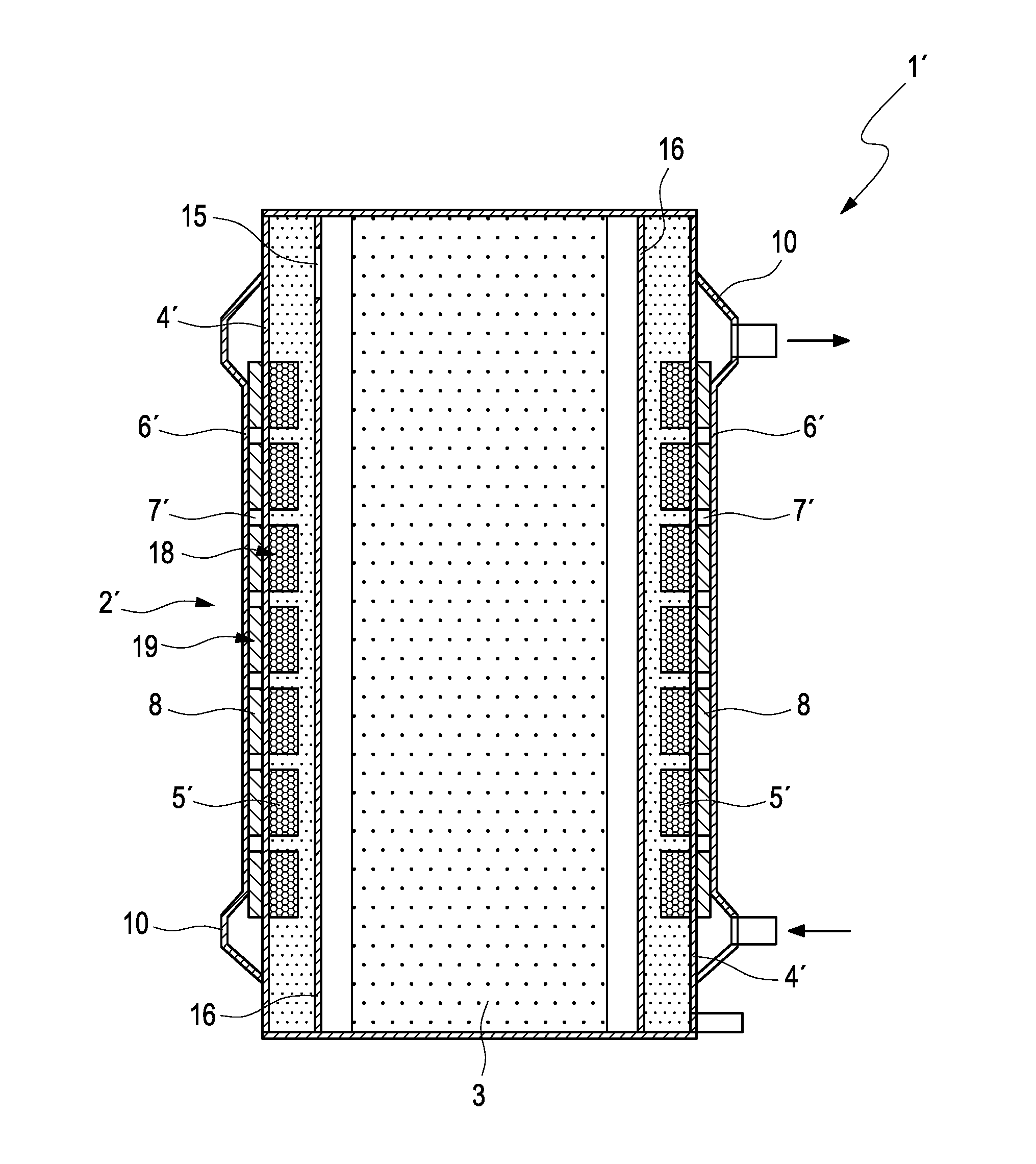
[0039] FIG. 2 shows an axial section through a further sorption heat transfer module according to the invention with thermally activatable housing and a dividing wall between phase change structure and sorption zone;
[0040] FIG. 3a shows a perspective view of yet another sorption heat transfer module according to the invention with corrugated fins soldered on the front side;
[0041] FIG. 3b shows a plan view of the sorption heat transfer module from FIG. 3a;
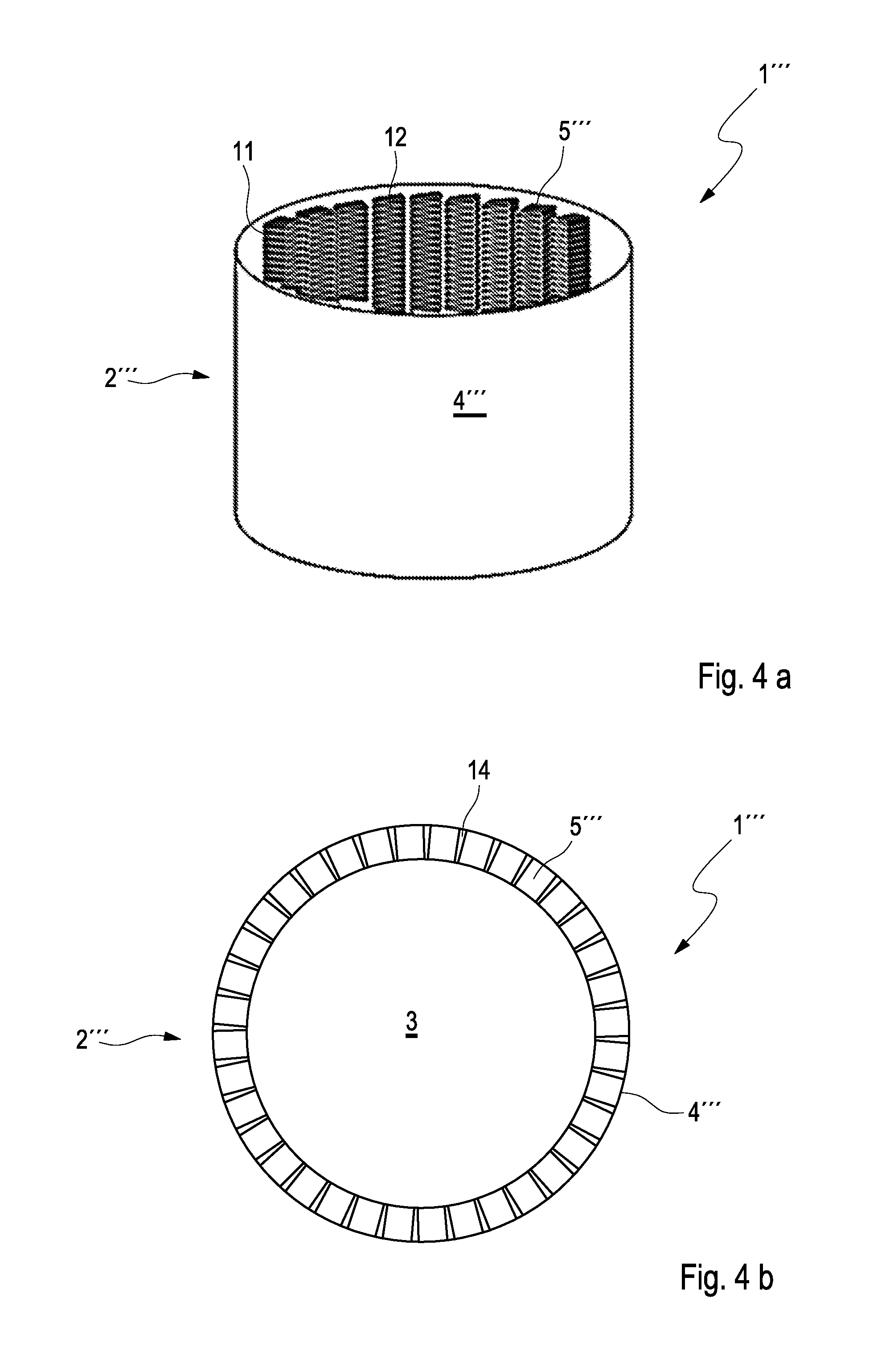
[0042] FIG. 4a shows a perspective view of yet another sorption heat transfer module according to the invention with corrugated fins soldered on the front side and
[0043] FIG. 4b shows a plan view of the sorption heat transfer module from FIG. 4a.
DETAILED DESCRIPTION
[0044] FIG. 1a shows a radial section through a first sorption heat transfer module 1 according to the invention with thermally activatable housing 2. This housing 2 encloses a sorption zone 3, which according to the known prior art comprises a plurality of flat tubes which with adsorption shaped bodies are applied to the flat tubes by means of adhesive bonding with good thermal contact. Furthermore, according to the prior art, the inner region can contain further installations for extending the functionality and/or for reducing the loss effects during operation of the sorption heat transfer module 1 which however are not the subject of the present invention.
[0045] In this first embodiment as a phase change structure, an annular corrugated fin package 5 rolled from tin-plated copper strip is applied by soft soldering with good thermal contact to the internal surface of a gas-tight inner wall 4 which here consists of tin plate. This corrugated fin package 5 here represents a capillary structure 18. The width of the at least one annular corrugated fin package 5 is dimensioned so that with a preferred fin density between 200 Ri/dm and 400 Ri/dm, the capillary force is sufficient to hold condensed working medium in a fixed position against gravity and optionally predictable acceleration forces. The width of a corrugated fin package 5 lies between 10 mm and 30 mm, preferably between 15 mm and 25 mm.
[0046] The housing 2 also comprises an outer wall 6 which together with the gas-tight inner wall 4 forms an annular channel 7 which has a fluidic, i.e. liquid and/or gaseous heat transfer agent flowing through it in the axial direction. In order to increase the thermal conductivity, a heat-conducting structure 19 in the form of another corrugated fin package 8 is provided, which is soft-soldered to the inner wall 4. For thermal insulation the outer wall 6 is separated from the heat-conducting structure 19 by an insulating layer 9.
[0047] In the axial direction of this inner wall 4, which is designed to be cylindrical here merely as an example, a plurality of such annular closed corrugated fin packages 5 are arranged axially at a distance from one another in such a manner that no capillary bridges are formed between the annular packages 5. This is achieved by axial spacings between 1 and 4 mm. Particularly preferred spacings lie in the range between 2 mm and 3 mm.
[0048] FIG. 1b shows a detailed view 17 of the thermally activatable housing 2 of the sorption heat transfer module 1 from FIG. 1a. It can be identified therein that the external surface of the inner wall 4 has a fin structure which is also connected to this inner wall 4 by soft soldering with very good thermal contact. Together with the outer wall 6 the finned annular channel 7 is thereby formed through which a heat transfer agent can be guided in the axial direction with a very good heat transfer coefficient. Furthermore, it can be seen that the outer wall 6 is not thermally connected to the corrugated fin package 8 of the heat-conducting structure 19 and is even spaced apart from the heat-conducting structure 19 so that the thermal contact remains as small as possible. An annular gap remaining between fin structure and outer jacket can be filled by an insulating layer 9 such as a silicone foam mat. The desired thermal decoupling with respect to the outer wall 6 serves the purpose that the sensible heat is minimized during thermal cycling of the sorption heat transfer module 1 by reducing the connected thermal mass. In this first embodiment of a sorption heat transfer module 1 according to the invention, the corrugated fin packages 5 and 8 which are closed over the circumference of the housing 2 are soft-soldered via their tips 11 to the gas-tight inner wall 4, whilst a front face 12 of the individual corrugated fin packages 5 and 8 points in the axial direction.
[0049] It can be further deduced from FIGS. 1a and 1b that the inner wall 4 and the outer wall 6 are each cylindrically configured, that the inner wall 4 is arranged coaxially and concentrically in the outer wall 6 and that the annular channel 7 is arranged radially between the inner wall 4 and the outer wall 6. It is further shown in FIG. 1b that the annular channel 7 has smaller dimensions in the radial direction than the capillary structure 18. In addition, as explained previously it is provided that an external surface of the inner wall 4 is adjoined by said heat-conducting structure 19, which is connected in a firmly bonded manner to the inner wall 4 and which preferably consists of at least one corrugated fin package 8. It can be seen here that the heat-conducting structure 19 is arranged in the annular channel 7. In addition, it is provided that the heat-conducting structure 19 extends in an annular form in the annular channel 7. Furthermore, starting from the inner wall 4 the heat-conducting structure 19 can extend in the annular channel 7 over 80% or over 85% or over 90% or over 95% or more than 95% of a radial channel width 20 of the annular channel 7. Particularly advantageously said thermally insulating layer 9, preferably a silicone foam mat, can be arranged in the annular channel 7 radially between the heat-conducting structure 19 and the outer wall 6. The radial dimensions of annular channel 7, heat-conducting structure 19 and insulating layer 9 are matched to one another here so that the insulating layer 9 abuts radially inwards against the heat-conducting structure 19 and radially outwards against the outer wall 6. Finally it is provided here that the heat-conducting structure 19 has smaller dimensions in the radial direction than the capillary structure 18 whereas the capillary structure 18 has larger dimensions in the radial direction than the annular channel 7.
[0050] FIG. 2 shows an axial section through another sorption heat transfer module 1' according to the invention with thermally activatable housing 2' which simultaneously contains or forms the phase change structure. The central, non-differentiated sorption zone 3 and the structure of the thermally activatable housing 2' with two annular distribution chambers for heat transfer agent can substantially be identified. One of these distribution chambers is formed by a cylindrical outer wall 6' together with a gas-tight inner wall 4' and forms a finned annular channel 7' through which flow can take place in the axial direction. Furthermore, seven annular corrugated fin packages 5' can be identified in this diagram as a condensate-storing phase change structure which is soldered to the internal surface of the inner wall 4' with good thermal contact.
[0051] The entire gas chamber between the central sorption zone 3 operated at higher temperature levels and the external phase change zone which can be activated via the temperature-controllable inner wall 4' is here divided into two partial chambers by another cylindrical dividing wall 16. This dividing wall 16 is provided with a through opening 15, via which the vaporous working medium is transported between the two zones. The intermediate cylinder is used for thermal separation of the two differently temperature-controlled zones of the sorption heat transfer module 1'. The annular channel 7' has respectively one inlet-side and one outlet-side annular beading 10, which is used for a homogeneous distribution of the axially directed volume flow in the circumferential direction.
[0052] FIG. 3a show a perspective view of yet another sorption heat transfer module 1'' according to the invention with corrugated fins 5'' soldered on the front side, which are attached to an inner wall 4'' of a housing 2'' in several axial positions spaced apart from one another. In this second embodiment of a sorption heat transfer module according to the invention, it can be seen that the corrugated fin packages 5'' are turned through 90.degree. there, i.e. are soldered with their front faces 12 to the internal surface of the inner wall 4''. Furthermore, these corrugated fin packages 5'' preferably have no gills or other inner openings in order to reduce the harmful influence of a condensate displacement due to gravity and acceleration effects. In this perspective view it can be seen that here also a plurality of corrugated fin packages 5'' are arranged axially spaced apart above one another in order to form a larger area of the housing 2'' as phase change zone. Since in this second embodiment, the capillary retaining effect of the corrugated fin packages 5'' in particular when the sorption heat transfer module 1'' is installed in a vertical position has a lesser importance due to the gill-less structure, the fin density can be brought to lower values.
[0053] Preferably the corrugated fin packages 5'' which are soldered on annularly on the inside have spaced-apart openings in the circumferential direction which enable a small axially parallel gas transport. These serve the purpose that non-condensable external gases which accumulate there are flushed away in the axially parallel direction and can accumulate in an axial end region in order to be sucked away there in concentrated form as required according to the prior art.
[0054] FIG. 3b shows a radial section through the sorption heat transfer module 1'' from FIG. 3a in which two easy-to-implement possibilities for achieving such rinsing channels are shown. For example, before forming into a corrugated fin, the metal strip can have through openings 13 in the form of recesses at the edge to be soldered subsequently, which have the result that at certain spacings the solder edge is set back so far that no soldering occurs there. Particularly preferably the length of the edge setback in the longitudinal direction of the strip is selected so that at least a corrugation hill and/or corrugation valley of the corrugated fin is not soldered on as is shown schematically in the upper half of FIG. 3b.
[0055] The lower half of FIG. 3b shows a division of each corrugated fin package 5'' into a plurality of separate, in the present case, eight partial packages between which axial gas transport is possible. Advantageously through openings 13' in the form of interruptions of two corrugated fin packages 5'' arranged one above the other, are arranged offset with respect to one another in order to enable rinsing transport of undesirable non-condensable external gases in the principal direction of flow.
[0056] The through openings 13, 13' for axial gas transport serve the purpose that non-condensable gases accumulating between the corrugated fin packages 5'' cannot accumulate there in harmful concentration but are transported following the principal direction of flow in the direction of that axial end of the housing 2'' which has a displacement chamber and/or a blow-off or extraction opening through which these harmful gases can be removed from the housing 2'' as required.
[0057] The structure applied to the outside of the gas-tight inner wall 4'' to improve the heat transfer on the heat transfer agent side can be designed in a similar manner to the first embodiment of FIG. 1. There also the fin structure can consist of a plurality of annular layers, whose soldered connecting surfaces preferably overlap with the annular phase change structures soldered on the inside.
[0058] FIG. 4a shows a perspective view of yet another sorption heat transfer module 1''' according to the invention with corrugated fins soldered on the front side. There the individual corrugated fin packages 5''' are soldered on the inner wall 4''' of the sorption heat transfer module 1''' axially parallel to the front face 12. The corrugated fin packages 5''' are connected in a firmly bonded manner to the inner wall 4''', for example by soft soldering. The outer finned structure for the axial flow through the housing 2''' is not shown here.
[0059] FIG. 4b shows a radial section through the sorption heat transfer module 1''' of FIG. 4a. It can be seen that wedge-shaped axial flow channels 14 are formed between the individual corrugated fin packages 5''' which enable an axial transport, for example of a methanol vapour to be condensed and contribute towards a flushing of non-condensable external gases onto an axial end of the gas chamber. Preferably the corrugated fin packages 5''' are positioned here so that on the one hand the highest possible surface density of the cylinder is achieved but on the other hand the corrugated fin packages 5''' do not touch each other. As a result of this particularly preferred arrangement of the corrugated fin packages 5''', a displacement of condensate due to gravity and acceleration in the horizontal and vertical position of the sorption module is particularly effectively prevented.
[0060] According to the depicted fundamental embodiments of a front-side or tip-side application of the corrugated fin packages 5 . . . 5''', the thermally activatable housing implemented according to the invention affords manifold advantages compared to known solutions. Thus, the very high attainable heat transfer coefficient between fluid temperature and saturated vapour temperature of the working medium only requires very small driving temperature differences for the removal of condensation heat and supply of evaporation heat and thereby increases the efficiency and the power density of the sorption heat transfer module. In addition, the optionally tin-plated semi-finished product materials such as for example tin plate for the gas-tight inner wall and optionally tin-plated copper strip for fabricating the phase change structure in the form of corrugated fin packages having a high fin density and thus attainable capillary condensate retaining function and the surface-enlarging fin system of the annular channel for fluidic flow enable a very cost-effective and thermally very good conducting joining process of the three required structure components. In particular, the particularly preferred second embodiment of a sorption heat transfer module according to the invention in FIGS. 3 and 4 makes it easy to vary the receiving capacity of the phase change structure by varying the strip width. In addition, the fin orientation of this embodiment avoids flow-off effects of stored condensate since no passage paths are provided due to a smooth gill-less fin design. This fin orientation is therefore suitable both for horizontal and for vertical module installation. This particularly preferred second embodiment additionally has the advantage of easier applicability of the individual corrugated fin packages and axially assisted vapour flow with external gas flushing effect.
[0061] The axial flow through the housing 2 . . . 2''' is however not necessarily advantageous. The material combination based on steel materials is due to the favoured alcohol working media (methanol, ethanol). When using water as working medium, aluminium-based materials can also be used but these cannot be soft-soldered cost-effectively. In general purely cylindrical designs can also be avoided but these have a lower differential compressive strength and require more complex forming methods and/or thicker wall thicknesses such as, for example, internal high-pressure forming.
* * * * *
D00000
D00001
D00002
D00003
D00004
XML
uspto.report is an independent third-party trademark research tool that is not affiliated, endorsed, or sponsored by the United States Patent and Trademark Office (USPTO) or any other governmental organization. The information provided by uspto.report is based on publicly available data at the time of writing and is intended for informational purposes only.
While we strive to provide accurate and up-to-date information, we do not guarantee the accuracy, completeness, reliability, or suitability of the information displayed on this site. The use of this site is at your own risk. Any reliance you place on such information is therefore strictly at your own risk.
All official trademark data, including owner information, should be verified by visiting the official USPTO website at www.uspto.gov. This site is not intended to replace professional legal advice and should not be used as a substitute for consulting with a legal professional who is knowledgeable about trademark law.