Method And Device For Controlling A Turbocharger
HOLECEK; Jakub ; et al.
U.S. patent application number 16/064463 was filed with the patent office on 2019-03-07 for method and device for controlling a turbocharger. The applicant listed for this patent is GE Jenbacher GmbH & Co. OG. Invention is credited to Jakub HOLECEK, Guenther WALL.
| Application Number | 20190072045 16/064463 |
| Document ID | / |
| Family ID | 57754882 |
| Filed Date | 2019-03-07 |
| United States Patent Application | 20190072045 |
| Kind Code | A1 |
| HOLECEK; Jakub ; et al. | March 7, 2019 |
METHOD AND DEVICE FOR CONTROLLING A TURBOCHARGER
Abstract
A method for establishing a permitted maximum differential pressure (.DELTA.p.sub.max) of an air filter (3) arranged in an intake tract (2) of an internal combustion engine (1), wherein a control reserve of the internal combustion engine (1) is determined and the maximum permissible differential pressure (.DELTA.p.sub.max) of the air filter (3) is established as a function of the determined control reserve.
| Inventors: | HOLECEK; Jakub; (Innsbruck, AT) ; WALL; Guenther; (Bad Haring, AT) | ||||||||||
| Applicant: |
|
||||||||||
|---|---|---|---|---|---|---|---|---|---|---|---|
| Family ID: | 57754882 | ||||||||||
| Appl. No.: | 16/064463 | ||||||||||
| Filed: | December 7, 2016 | ||||||||||
| PCT Filed: | December 7, 2016 | ||||||||||
| PCT NO: | PCT/AT2016/060119 | ||||||||||
| 371 Date: | November 13, 2018 |
| Current U.S. Class: | 1/1 |
| Current CPC Class: | F02M 35/09 20130101; F02B 37/16 20130101; Y02T 10/12 20130101; Y02T 10/144 20130101; F02D 2200/0406 20130101; F02B 37/18 20130101; F02M 35/0208 20130101; F02D 41/22 20130101; F02D 41/0007 20130101 |
| International Class: | F02D 41/00 20060101 F02D041/00; F02B 37/16 20060101 F02B037/16; F02B 37/18 20060101 F02B037/18; F02D 41/22 20060101 F02D041/22; F02M 35/02 20060101 F02M035/02 |
Foreign Application Data
| Date | Code | Application Number |
|---|---|---|
| Dec 29, 2015 | AT | A51107/2015 |
Claims
1. A method for establishing a permitted maximum differential pressure (.DELTA.p.sub.max) of an air filter (3) arranged in an intake tract (2) of an internal combustion engine (1), wherein a control reserve of the internal combustion engine (1) is determined and the maximum permissible differential pressure (.DELTA.p.sub.max) of the air filter (3) is established as a function of the determined control reserve.
2. A method according to claim 1, wherein a control range of a control variable for the flow of a fuel-air mixture or an exhaust gas is used as a control reserve, wherein preferably the following variables are used in isolation or any combination: the position of a bypass valve (4) of a turbocharger bypass (5) of the internal combustion engine (1) the position of a throttle valve (6) of the internal combustion engine (1) the position of a wastegate (7) an adjustable geometry of a turbocharger (8)
3. A method according to claim 1 or 2, wherein as control reserve the following can be used isolated or in combination: a control range of a control element for the specific energy density of the fuel-air mixture, preferably a lambda value a control range of a control element for the ignition time for the spark ignition of a fuel-air mixture in the combustion chambers of the internal combustion engine a control range of a control element for the volumetric efficiency, preferably adjustment of a variable valve train a control range of a control element for an EGR rate
4. A method according to at least one of the preceding claims, wherein a load state of the air filter (3) is being determined.
5. A method according to at least one of the preceding claims, wherein: a standard air flow is calculated from the operating variables of the internal combustion engine the actual present air flow is calculated taking into account the ambient pressure and the charge-air temperature from the standard air flow a comparison of a measured differential pressure (.DELTA.p) via the air filter with the maximum permitted differential pressure (.DELTA.p.sub.max) for the actual present air flow takes place
6. A method according to claim 5, wherein the measurement of the actually present differential pressure (.DELTA.p) and of the operating variables of the internal combustion engine (1) for the calculation of the standard air flow and the measurement of the ambient pressure and the charge-air temperature can be done continuously or cyclically.
7. A method according to at least one of the preceding claims, wherein based on the calculated actual present air flow and a maximum permitted differential pressure (.DELTA.p.sub.max) adjusted via the actual present air flow, the load condition and/or the remaining operating time of the air filter (3), particularly in a partial-load operation, of the internal combustion engine is estimated.
8. A method according to at least one of the preceding claims, wherein the degradation of the air filter (3) and the internal combustion engine (1) are monitored and it gets calculated which maximum permitted differential pressure (.DELTA.p.sub.max) may be authorized and/or extrapolated into the future and estimated, when the air filter (3) must be replaced.
9. Internal combustion engine (1) comprising at least one air filter (3) arranged in an intake tract (2) of an internal combustion engine (1) a control device (9), in which a maximum permitted differential pressure (.DELTA.p.sub.max) for the air filter can be stored characterized in that the control device (9) is designed to determine a specific control reserve of the internal combustion engine (1) and the maximum permitted differential pressure (.DELTA.p.sub.max) of the air filter (3) from the measurement values of the at least one sensor and the operating data of the internal combustion engine (1) as a function of the determined control reserve.
10. An internal combustion engine according to the preceding claim, wherein a control range of a control variable for the flow of a fuel-air mixture or an exhaust gas is given as a control reserve, preferably in isolation or any combination: the position of a bypass valve (4) of a turbocharger bypass (5) of the internal combustion engine (1) the position of a throttle valve (6) of the internal combustion engine (1) the position of a wastegate (7) an adjustable geometry of a turbocharger (8)
11. An internal combustion engine according to at least one of the preceding claims, wherein the control reserve is given by: a control range of a control element for the specific energy density of the fuel-air mixture, preferably a lambda value a control range of a control element for the ignition time for the spark ignition of a fuel-air mixture in the combustion chambers of the internal combustion engine a control range of a control element for the volumetric efficiency, preferably adjustment of a variable valve train a control range of a control element for an EGR rate
12. An internal combustion engine according to at least one of the preceding claims, wherein the control device (9) is designed to determine the load state of the air filter (3).
13. An internal combustion engine according to at least one of the preceding claims, wherein the control device (9) is designed to: calculate a standard air flow from the operating variables of the internal combustion engine (1) calculate an actual present air flow taking into account the ambient pressure and the charge air temperature from the standard air flow carry out a comparison of a measured differential pressure (.DELTA.p) via the air filter (3) with the maximum permitted differential pressure (.DELTA.p.sub.max) for the actual present air flow
14. An internal combustion engine according to at least one of the preceding claims, wherein the control device (9) is designed to carry out the measurement of the actual present differential pressure (.DELTA.p) and of the operating variables of the internal combustion engine (1) for the calculation of the standard air flow and the measurement of the ambient pressure and the charge-air temperature continuously or cyclically.
Description
[0001] The present invention relates to a method with the features of the preamble of claim 1 and an internal combustion engine with the features of the preamble of claim 9.
[0002] The degradation (aging or wear) of internal combustion engines in terms of control technology has up to now been compensated by making use of the control reserve of a turbocharger bypass (the control reserve of the turbocharger bypass is given by that control range of the bypass valve which does not have to be provided for the normal operation of the internal combustion engine), wherein the compressor (and/or an exhaust-gas turbine, then it is called a wastegate) of a turbocharger is flowed around by the turbocharger bypass.
[0003] In a newly manufactured internal combustion engine this control reserve can be used as an additional pressure drop in an intake tract of the internal combustion engine, as long as the turbocharger is operated within the specified operating limits. With increasing degradation of the internal combustion engine, the control reserve of the turbocharger bypass must be used to compensate for the effects of degradation, so that in the end the additional pressure drop in the intake tract is reduced to the initial value.
[0004] Air filters of internal combustion engines are used to separate particles from the charge air and to ensure a certain purity of the charge air. The air filter is thereby subject to an aging process, which is called load, and which traces back to separated particles in the filter media. As a result, the differential pressure (difference of the pressure in the intake tract upstream of the air filter and of the pressure downstream of the air filter) increases in the course of increasing operating hours. This differential pressure is part of the total pressure drop through the intake tract, which leads to an increase in the compression ratio of the turbocharger and a reduced control reserve for the turbocharger bypass. It is therefore necessary to limit the maximum pressure drop and thus the maximum permitted differential pressure via the air filter in order to continue to allow operation of the turbocharger within the operating limits using the control reserve of the turbocharger bypass.
[0005] The service life of an air filter depends on the state of the supplied charge air (environmental conditions, dust load) for a given size of the air filter, the operation mode of the internal combustion engine and the specified maximum permitted differential pressure.
[0006] U.S. Pat. No. 5,606,311 and U.S. Pat. No. 8,626,456 describe the measurement of a pressure drop via an air filter and the comparison with a specified maximum permitted differential pressure to determine a degradation of the air filter.
[0007] U.S. Pat. No. 8,534,123 reveals the economic optimization of the replacement intervals for an air filter based on fuel consumption, the differential pressure via the air filter and the cost.
[0008] U.S. Pat. No. 9,061,224 extrapolates a remaining service life of the air filter.
[0009] It has been found that the assessment of the state of an air filter, which is based solely on the differential pressure, commonly causes a too early replacement of such a still usable air filter.
[0010] The object of the invention is to provide a generic method and a generic internal combustion engine in which the above-described problems are resolved.
[0011] This object is achieved by a method with the features of claim 1 and an internal combustion engine with the features of claim 9. Advantageous embodiments of the invention are defined in the dependent claims.
[0012] By control reserve in the present disclosure is that control range of a control element meant, which in the normal control operation of the internal combustion engine must not be used.
[0013] The remaining control reserve, e.g. of a compressor bypass, which is dependent on the degradation state of an internal combustion engine, can be used to adjust the maximum permitted differential pressure of an air filter and while still maintaining an acceptable control reserve. This increases the service life of the air filter, since a greater maximum permitted differential pressure can be tolerated.
[0014] The control reserve (shown here with the example of a compressor bypass) is the ratio between compressor bypass mass flow to compressor total mass flow. The bypass mass flow is derived from the operating pressures and the pressure loss characteristic curve of the valve manufacturer. The total mass flow can be calculated with the knowledge of the person skilled in the art from the cubic capacity of a single combustion chamber, the number of combustion chambers, the volumetric efficiency, the charge-air pressure, the charge temperature and the charge-air density of the internal combustion engine as well as the speed.
[0015] As it is known, how big the control reserve is, it can be used to allow a higher maximum permitted differential pressure for the air filter. If the internal combustion engine is degraded, this control reserve decreases and the maximum permitted differential pressure must be reduced.
[0016] A remaining control range of a control variable for the current of a fuel-air mixture or an exhaust gas can be used as a control reserve by the internal combustion engine. Examples for such a control reserve, which can be used in any combination, in addition to the position of a bypass valve of a turbocharger bypass, e.g. the position of the throttle valve of the internal combustion engine, are the position of a wastegate, an adjustable geometry of the turbocharger, etc.
[0017] In addition or alternatively, a control element for the specific energy density of the fuel-air mixture (lambda value)--for example a gas metering valve--or a control element for the spark ignition time for the spark ignition of a fuel-air mixture in the combustion chambers of the internal combustion engine) can be isolated or used in any combination as a control reserve or for the volumetric efficiency (a variable valve train adjustment) or for an EGR rate (exhaust gas recirculation rate).
[0018] It is preferably provided that a load state of the air filter is being determined. The load state can, for example, be determined by measuring the present differential pressure of the air filter or by weighing the air filter. An appropriate scale can be implemented, for example, in a storage of the air filter so that the measurement can take place during the operation of the internal combustion engine without disassembly of the air filter.
[0019] It is preferably provided to calculate a standard air flow from operating variables of the internal combustion engine (for example, according to the above calculation of the compressor mass flow minus the compressor bypass and propellant gas mass flow using the standard density for air). The actual present air flow can be calculated in a well-known manner taking into account the ambient pressure and the charge-air temperature from the standard air flow. The comparison of a measured differential pressure via the air filter with the maximum permitted differential pressure can take place for the actually present air flow.
[0020] The maximum permitted differential pressure present at a specified time and the differential pressure measured can be reported by a control device of the internal combustion engine to an operator of the internal combustion engine.
[0021] The measurement of the actually present differential pressure (which is representative of a load state of the air filter) and of the operating variables of the internal combustion engine for the calculation of the standard air flow and the measurement of the ambient pressure and the charge-air temperature can be done continuously or cyclically.
[0022] It is preferably provided that the degradation of the air filter and also that of the internal combustion engine is monitored and [0023] that it gets calculated which maximum permitted differential pressure may be authorized [0024] and/or extrapolated into the future and estimated, when the air filter must be replaced.
[0025] Preferably, the internal combustion engine is designed as spark-ignited gas engine. Preferably, the internal combustion engine is designed as a stationary internal combustion engine, particularly preferably as part of a genset for the production of electrical energy.
[0026] Exemplary embodiments of the invention will be explained with reference to the figures. The figures show:
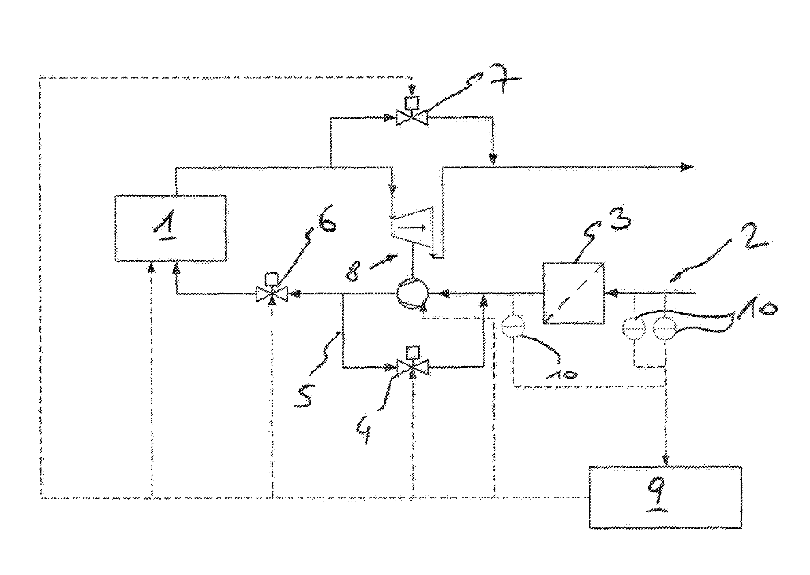
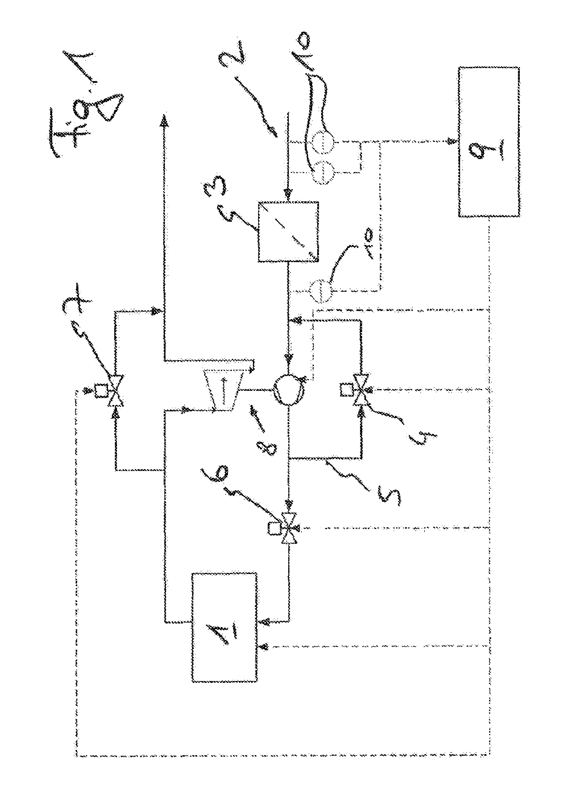
[0027] FIG. 1 schematically an internal combustion engine according to the invention
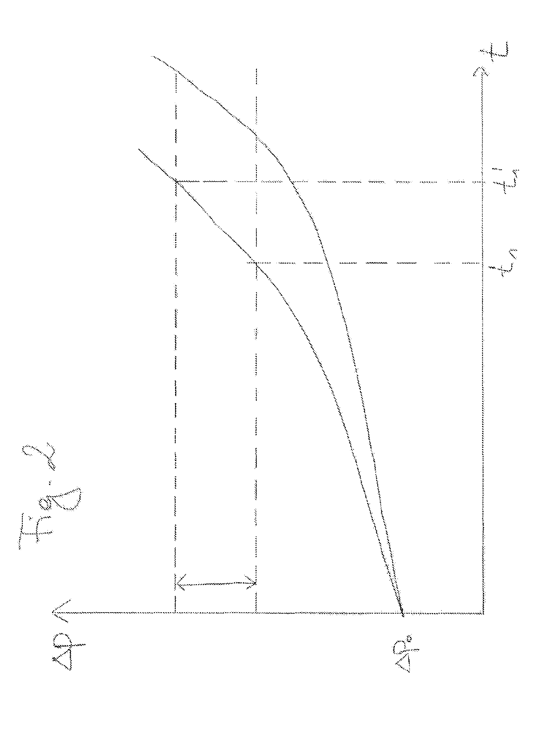
[0028] FIG. 2 the differential pressure applied via the air filter over the operating hours of an internal combustion engine and
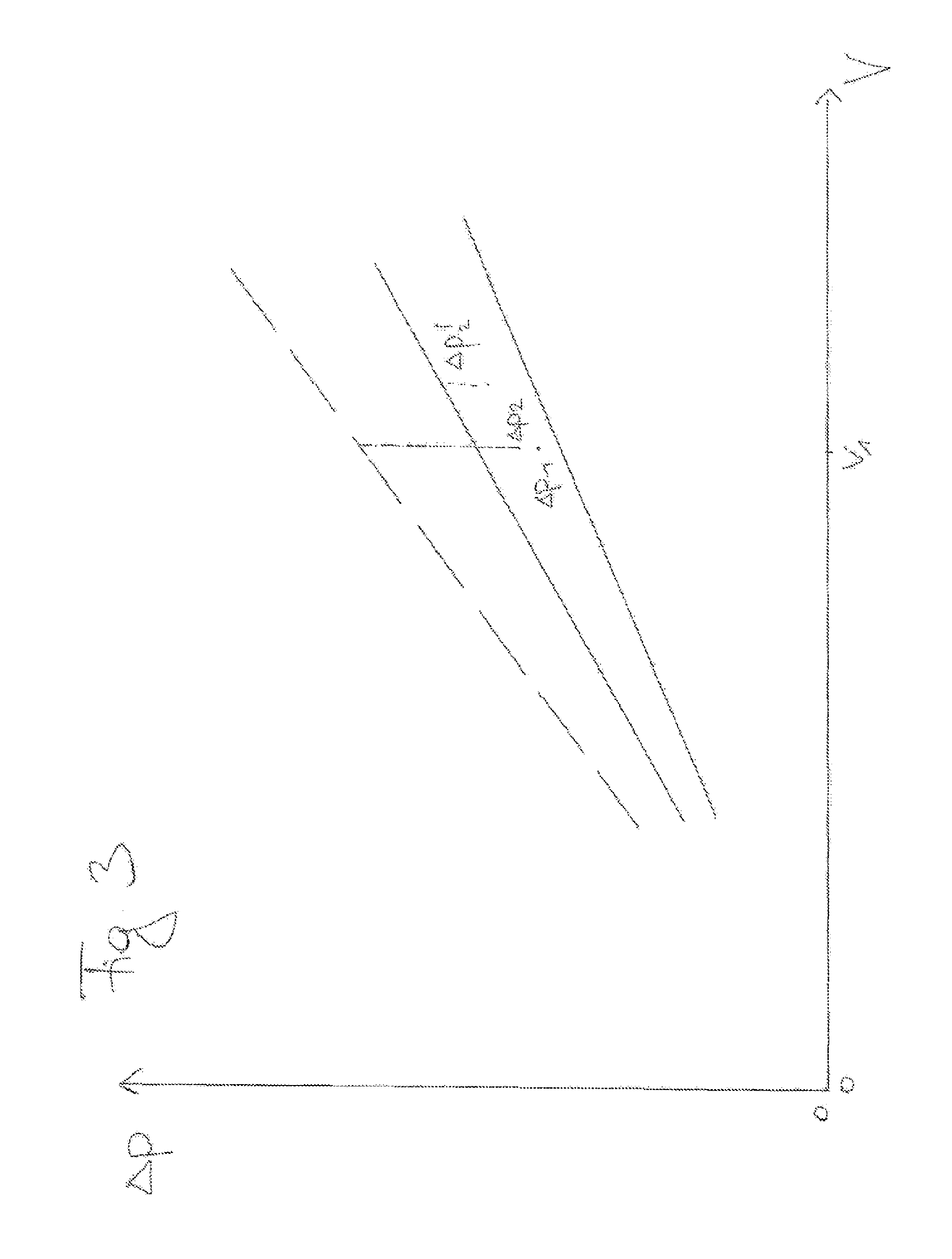
[0029] FIG. 3 the differential pressure applied via the air filter over the volume flow of the charge air.
[0030] FIG. 1 shows schematically an internal combustion engine 1 according to the invention with an intake tract 2 for charge air which can be supplied to the combustion chambers (not shown) of the internal combustion engine 1 and an air filter 3 arranged in the intake tract 2. The internal combustion engine 1 comprises a throttle valve 6, a wastegate 7, sensors 10 for the measurement of various operating variables and a control device 9 for the control of various control elements. A turbocharger 8 is provided, which can be flowed around a turbocharger bypass 5, depending on the position of a bypass valve 4.
[0031] FIG. 2 shows the increase of the differential pressure .DELTA.p over the number of operating hours for a typical internal combustion engine (for two different operating conditions of the internal combustion engine 1) starting from an initial differential pressure of .DELTA.p0. Drawn horizontally with dotted lines are two different values of the maximum permitted differential pressure .DELTA.p.sub.max. When the differential pressure .DELTA.p reaches the maximum permitted differential pressure .DELTA.p.sub.max, the air filter 3 must be replaced. The higher the maximum permitted differential pressure .DELTA.p.sub.max, the later this is the case. In the example shown, the two plotted values for the maximum permitted differential pressure .DELTA.p.sub.max differ by a control reserve of the internal combustion engine 1. By including this control reserve in the calculation of the maximum permitted differential pressure .DELTA.p.sub.max, an extension of the operating time of the air filter from time t1 to the time t1' can take place.
[0032] FIG. 3 shows a diagram with different operating points p1, p2, p2' of the air filter, wherein the differential pressure .DELTA.p is applied against the actually present volume flow V. Delineated is the maximum permitted differential pressure .DELTA.p.sub.ma x(upper solid straight line) in dependence of the actual present volume flow V, and a minimum permitted differential pressure (lower solid straight line), also in dependence of the volume flow V.
[0033] If the maximum permitted differential pressure .DELTA.p.sub.max is exceeded, the air filter must be changed. This also applies when the minimum permitted differential pressure drops below, since generally there is a defective air filter then.
[0034] Here follows the description of a typical aging process of an air filter based on the diagram in FIG. 3. At the first measurement of the differential pressure .DELTA.p and the first volume flow V at a first time, a first differential pressure .DELTA.p1 is measured at volume flow V1. With unchanged operating conditions, in particular an unchanged volume flow, a second differential pressure .DELTA.p2 is measured at a later time, which is already closer to the maximum permitted differential pressure .DELTA.p.sub.max(with or without utilization of the control reserve). It can now be estimated how much time remains until the maximum permitted differential pressure .DELTA.p.sub.maxis reached (for example, by linear extrapolation).
[0035] If the operating conditions since the first measurement have changed (which here is noticeable in an increased volume flow V2), then the second measured differential pressure .DELTA.p2' will have a different distance to the maximum permitted differential pressure .DELTA.p.sub.max. Again, it can now be estimated how much time remains until the maximum permitted differential pressure .DELTA.p.sub.max is reached (for example, by linear extrapolation) even though the operating conditions have changed.
[0036] Based on the calculated actual present air flow and a maximum permitted differential pressure (.DELTA.p.sub.max) adjusted via the actual present air flow, the load condition and/or the remaining operating time of the air filter (3), particularly in a partial-load operation, of the internal combustion engine can be estimated.
* * * * *
D00000
D00001
D00002
D00003
XML
uspto.report is an independent third-party trademark research tool that is not affiliated, endorsed, or sponsored by the United States Patent and Trademark Office (USPTO) or any other governmental organization. The information provided by uspto.report is based on publicly available data at the time of writing and is intended for informational purposes only.
While we strive to provide accurate and up-to-date information, we do not guarantee the accuracy, completeness, reliability, or suitability of the information displayed on this site. The use of this site is at your own risk. Any reliance you place on such information is therefore strictly at your own risk.
All official trademark data, including owner information, should be verified by visiting the official USPTO website at www.uspto.gov. This site is not intended to replace professional legal advice and should not be used as a substitute for consulting with a legal professional who is knowledgeable about trademark law.