Leak Detection System For Intermittent Use Pipelines
Jaaskelainen; Mikko ; et al.
U.S. patent application number 16/075411 was filed with the patent office on 2019-03-07 for leak detection system for intermittent use pipelines. The applicant listed for this patent is Halliburton Energy Services, Inc.. Invention is credited to Mikko Jaaskelainen, Brian V. Park.
| Application Number | 20190071965 16/075411 |
| Document ID | / |
| Family ID | 60267034 |
| Filed Date | 2019-03-07 |

| United States Patent Application | 20190071965 |
| Kind Code | A1 |
| Jaaskelainen; Mikko ; et al. | March 7, 2019 |
LEAK DETECTION SYSTEM FOR INTERMITTENT USE PIPELINES
Abstract
A system is described for reliably detecting leaks in a distributed manner in intermittent use pipelines by making use of thermal or acoustic events triggered by the leak. The system can work in pressurized or unpressurized pipelines and in high flow or no flow conditions.
| Inventors: | Jaaskelainen; Mikko; (Katy, TX) ; Park; Brian V.; (Austin, TX) | ||||||||||
| Applicant: |
|
||||||||||
|---|---|---|---|---|---|---|---|---|---|---|---|
| Family ID: | 60267034 | ||||||||||
| Appl. No.: | 16/075411 | ||||||||||
| Filed: | May 11, 2016 | ||||||||||
| PCT Filed: | May 11, 2016 | ||||||||||
| PCT NO: | PCT/US2016/031808 | ||||||||||
| 371 Date: | August 3, 2018 |
| Current U.S. Class: | 1/1 |
| Current CPC Class: | F17D 5/02 20130101; F17D 5/04 20130101; G01M 3/38 20130101; G01M 3/047 20130101; E21B 47/135 20200501; E21B 47/06 20130101; E21B 47/117 20200501; E21B 47/113 20200501; G01M 3/002 20130101 |
| International Class: | E21B 47/10 20060101 E21B047/10; E21B 47/06 20060101 E21B047/06; E21B 47/12 20060101 E21B047/12 |
Claims
1. A system for detecting pipeline leaks for intermittent use pipelines comprising: a pipeline to carry a pipeline product that is be of at least intermittent use; a trough in which the pipeline is to rest; at least one optical fiber distributed sensing cable to run through the trough and to be located below the pipeline; separated baffles located along the trough to support the pipeline and to control a spacing between the pipeline and the at least one optical fiber distributed sensing cable; and a reactive material to be positioned in a bottom of the trough and to be in contact with the at least one optical fiber distributed sensing cable; wherein the reactive material is to react with the pipeline product if the reactive material comes in contact with the pipeline product, creating at least one of a thermal and an acoustic event.
2. The system of claim 1 wherein the at least one optical fiber distributed sensing cable is part of a distributed temperature sensing (DTS) system that is to detect thermal events along the pipeline.
3. The system of claim 1 wherein the at least one optical fiber distributed sensing cable is part of a distributed acoustic sensing (DAS) system that is to detect acoustic events along the pipeline.
4. The system of claim 1 wherein the pipeline product is a hydrochloric acid, wherein the reactive material at the bottom of the trough is calcium carbonate that is to react with the hydrochloric acid, releasing thermal energy that to be measured by a DTS system.
5. (canceled)
6. The system of claim 1 wherein the trough in which the pipeline rests comprises a V-shaped bottom.
7. The system of claim 1 wherein the reactive material is in granular form.
8. The system of claim 1 wherein a material of the pipeline is a hydrocarbon, wherein the reactive material is a material that is to dissolve in hydrocarbons, releasing acoustic energy that is to be measured by a DAS system.
9. (canceled)
10. The system of claim 1 wherein the reactive material is supplied as at least one of a gel and a brick form that is to stay in place in sloped pipeline deployments.
11. The system of claim 1 wherein the reactive material in the bottom of the trough is supplied encapsulated within a sensing cable to run through the trough and located below the pipeline.
12. A system for detecting pipeline leaks for intermittent use pipelines comprising: a pipeline carrying a pipeline product that is to be of at least intermittent use; a trough located in a trench in soil and with retaining walls surrounding the trench, wherein the pipeline is to be positioned in the trough; at least one optical fiber distributed sensing cable to run through the trough and to be located below the pipeline; a reactive material in a bottom of the trough and covering the at least one optical fiber distributed sensing cable; wherein the reactive material is to react with the pipeline product in response to being in contact with the pipeline product, creating at least one of a thermal and an acoustic event; and a trench lid to be placed on the retaining walls after deployment of the trough, the pipeline, the at least one optical fiber distributed sensing cable, and the reactive material.
13. The system of claim 12 wherein the at least one optical fiber distributed sensing cable is part of a distributed temperature sensing (DTS) system and is to detect thermal events along the pipeline.
14. The system of claim 12 wherein the at least one optical fiber distributed sensing cable is part of a distributed acoustic sensing (DAS) system and is to detect acoustic events along the pipeline.
15. The system of claim 12 wherein the pipeline product is a hydrochloric acid, wherein the reactive material at the bottom of the trough is calcium carbonate that is to react with the hydrochloric acid, releasing thermal energy that is to be measured by a distributed temperature sensing (DTS) system.
16. (canceled)
17. The system of claim 12 wherein the trough in which the pipeline rests comprises a V-shaped bottom.
18. The system of claim 12 wherein the reactive material is in granular form.
19. The system of claim 12 wherein a material of the pipeline is a hydrocarbon, wherein the reactive material is a material that is to dissolve in hydrocarbons, releasing acoustic energy that is to be measured by a distributed acoustic sensing (DAS) system.
20. (canceled)
21. The system of claim 12 wherein the reactive material is supplied as at least one of a gel and a brick form that is to stay in place in sloped pipeline deployments.
22. The system of claim 12 wherein the reactive material in the bottom of the trough is supplied encapsulated within a sensing cable to run through the trough and located below the pipeline.
23. A system for detecting pipeline leaks for intermittent use pipelines comprising: a pipeline to carry a pipeline product that is to be of at least intermittent use; at least one optical fiber distributed sensing cable to be positioned beneath the pipeline; and a reactive material supplied encapsulated within a sensing cable located below the pipeline; wherein the reactive material is to react with the pipeline product in response to being in contact with the, creating at least one of a thermal and an acoustic event.
24. The system of claim 23 wherein the optical fiber distributed sensing cable is part of at least one of a distributed temperature sensing (DTS) system that is to detect thermal events along the pipeline and a distributed acoustic sensing (DAS) system that is to detect acoustic events along the pipeline.
25. (canceled)
Description
BACKGROUND
[0001] The purpose of the invention is to enable leak detection in pipelines where the pipeline is intermittently used, i.e. extended periods of inactivity with low or no pressure in an environment where the pipeline fluid may approach the environmental ambient temperature. The pipeline may contain hydrocarbons, or for example be a buried hydrochloric acid pipeline intermittently used for down-hole well stimulation. Hydrochloric acid is often used to stimulate carbonate reservoirs by dissolving the carbonate formation, and the ground where the pipeline is buried may also be carbonate, which may be a concern if the hydrochloric pipeline leaks. The great challenge with any non-pressurized and intermittently used pipeline is the ability to detect a leak at any time.
[0002] Conventional leak detection systems utilize single point field instrumentation (e.g. for flow, pressure, fluid temperature) to monitor internal pipeline parameters, and these pipeline parameters are subsequently used for inferring a leak.
[0003] The issue with each of these types of sensors is: (a) when there is no flow, then the flow sensors used to measure normal flows will not be able to detect the low flows of a leak; (b) when there is no pressure then pressure sensors cannot detect a pressure change due to a leak; and (c) with a buried pipeline and no flow the pipeline contents will approach environmental temperatures so temperature sensors will not detect a leak.
[0004] Similarly, distributed fiber optic sensors like Distributed Temperature Sensing (DTS) or Distributed Acoustic Sensing (DAS) systems rely on deviations from a base line. But DTS systems--rely on the leaked fluid having a different temperature than the location where the optical fiber distributed sensing cable is located. This may not be the case with a buried pipeline where the fluid may approach the environmental temperature over time when the pipeline isn't in use. In the case of DAS systems--they rely on acoustic noise generated when the pipeline is pressurized and the sound generated when the fluid escapes the high pressure inside the pipeline. But this may not be case when the pipeline is inactive and not pressurized.
[0005] There are consequences to not detecting a leak. In the case of hydrochloric acid pipeline leaks during the inactive time may leak without means to detect the event. And the acid may then dissolve the carbonate foundation on which the pipeline rests, and other structures may also be impacted by a large acid leak.
[0006] There is a need for a better system that can detect small leaks during normal operation and also leaks during periods between well stimulation and pipeline usage if fluid is left in the pipeline.
BRIEF DESCRIPTION OF THE DRAWINGS
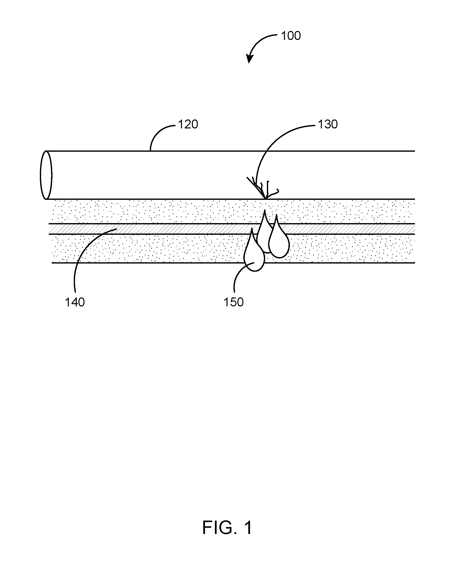
[0007] FIG. 1 FIG. 1 illustrates prior art deployment of optical fiber for pipeline leak detection.
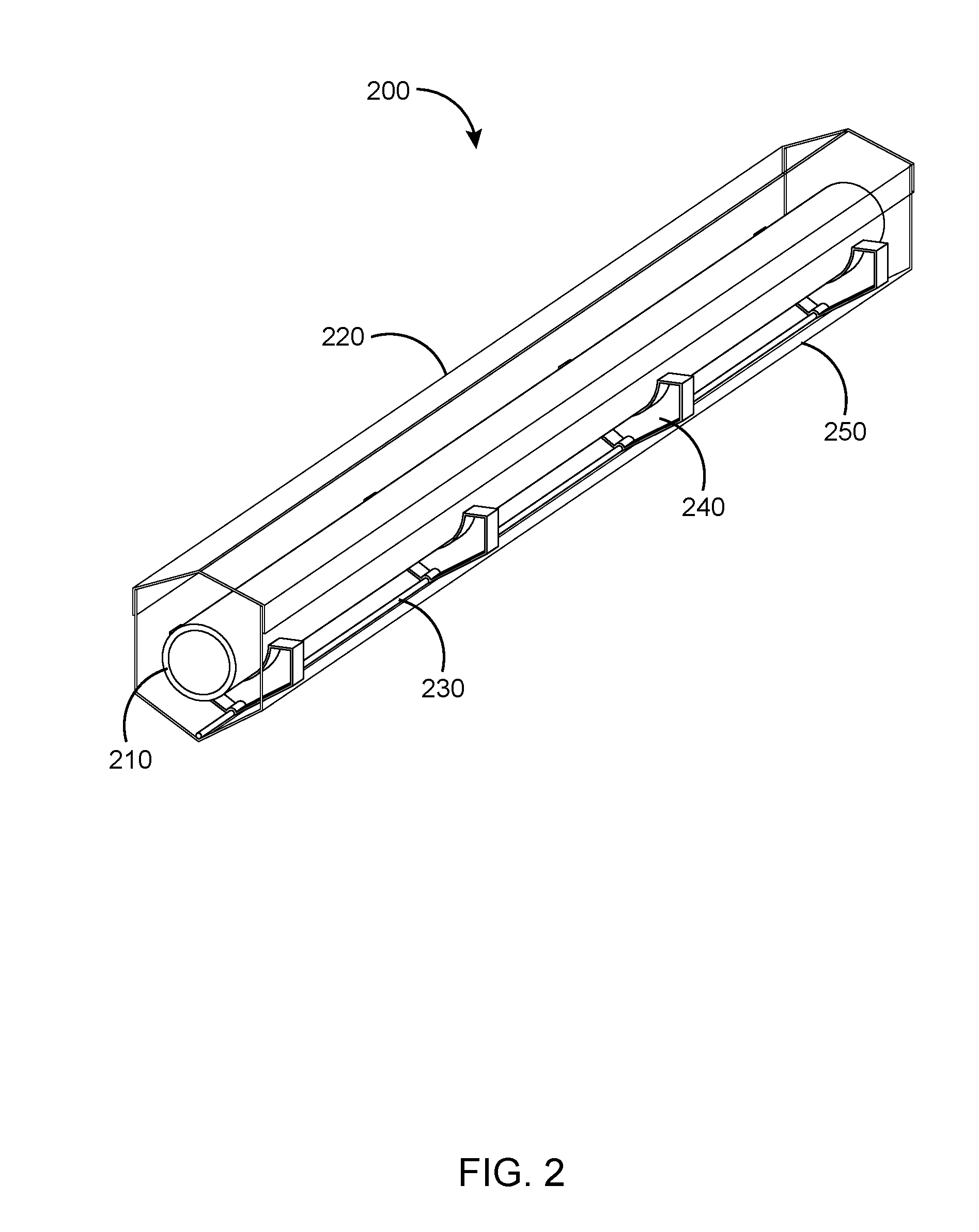
[0008] FIG. 2 illustrates an enhanced deployment method where environmental effects may be reduced.
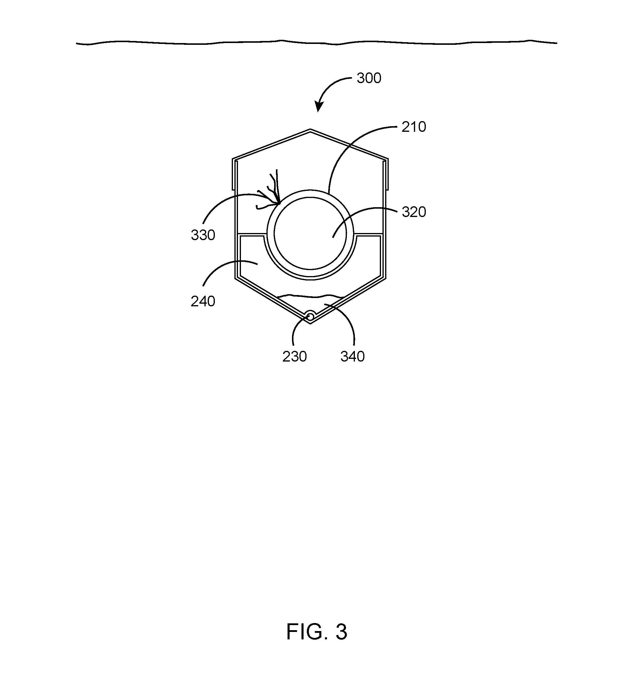
[0009] FIG. 3 illustrates a side view of the deployment of FIG. 2.
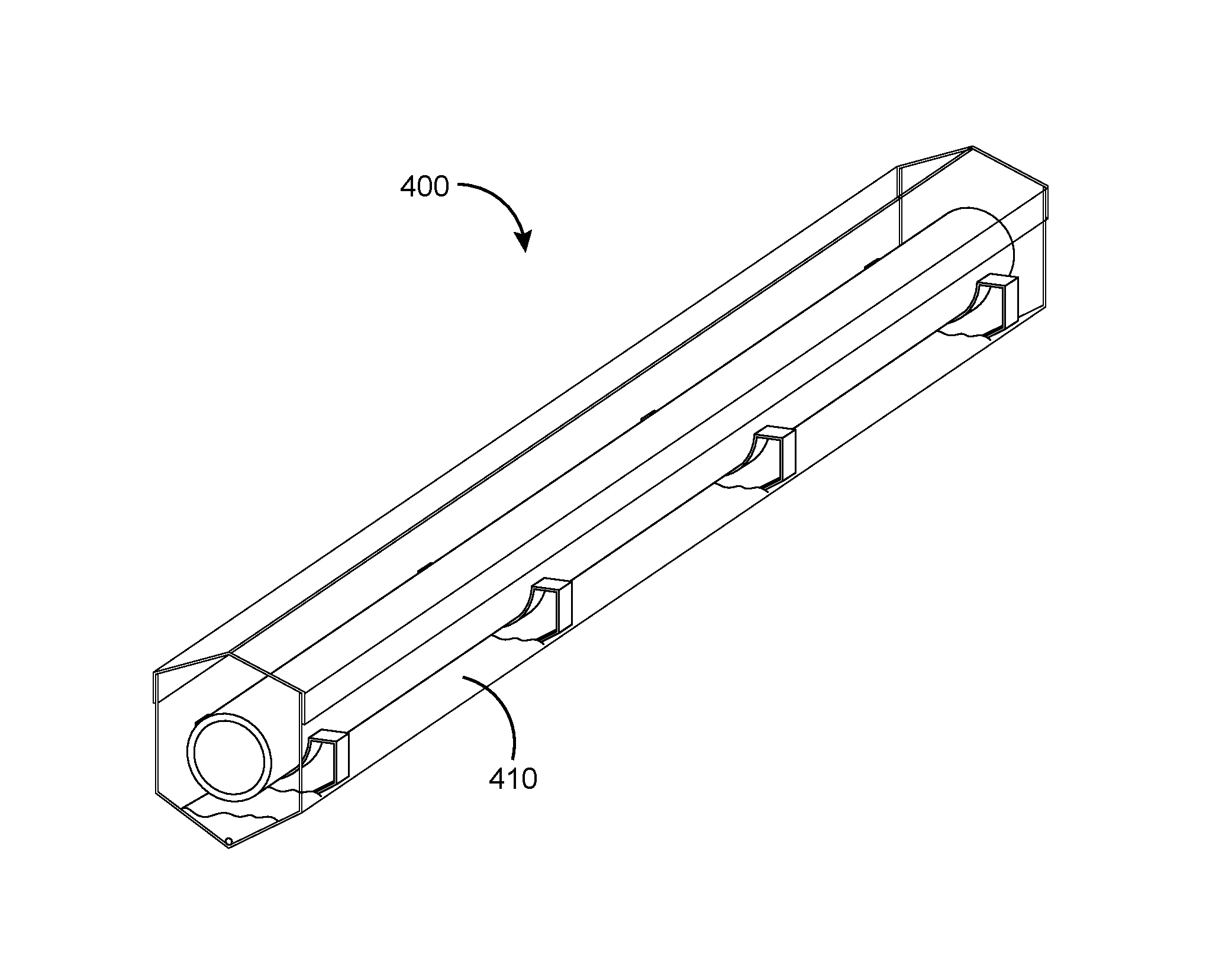
[0010] FIG. 4 illustrates a system that could achieve the desired objective.
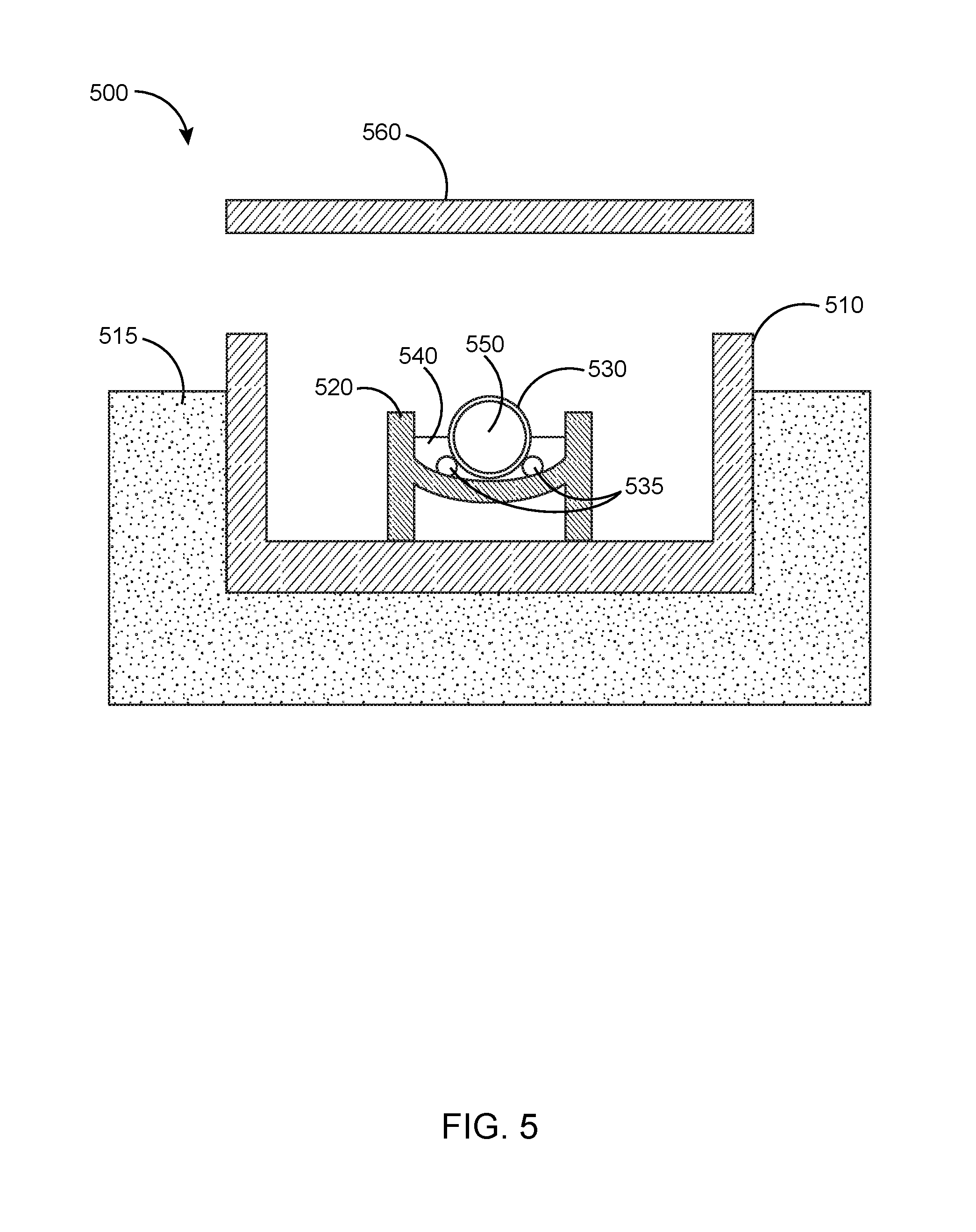
[0011] FIG. 5 illustrates an alternate embodiment in which a pipeline may be placed in a trough inside a buried trench.
DETAILED DESCRIPTION
[0012] In the following detailed description, reference is made to accompanying drawings that illustrate embodiments of the present disclosure. These embodiments are described in sufficient detail to enable a person of ordinary skill in the art to practice the disclosure without undue experimentation. It should be understood, however, that the embodiments and examples described herein are given by way of illustration only, and not by way of limitation. Various substitutions, modifications, additions, and rearrangements may be made without departing from the spirit of the present disclosure. Therefore, the description that follows is not to be taken in a limited sense, and the scope of the present disclosure will be defined only by the final claims.
[0013] The invention use materials deployed in the fluid leak path and the materials are selected such that exothermic reactions occur when the fluid contacts the material. The optical fiber distributed sensing cable is placed inside a trough to control leaked fluids towards the material and sensing cable such that the exothermic event is detected when the fluid contacts the material.
[0014] FIG. 1, shown generally as 100, illustrates prior art deployment of optical fiber for pipeline leak detection. The optical fiber cable 140 is buried below the pipeline 120 such that there is a thermal gradient between the pipeline 120 and the location where the sensing fiber optic is located. A leak 130 will cause fluid 150 of a one temperature to seep into the ground and eventually reach the optical fiber distributed sensing cable in an environment with a different temperature. This is detected by the fiber optic sensing system. The underlying assumption here is that there is a difference in temperature between the optical fiber distributed sensing cable 140 and the pipeline product, and that sufficient amount of pipeline product reaches the sensing cable to generate a decent size thermal event. This may not always be true due to soil variations, seasonal temperature changes, rain and other environmental effects.
[0015] FIG. 2, shown generally as 200, shows an enhanced deployment method where environmental effects may be reduced. A pipeline 210 is trenched and a glass fiber reinforced plastic (GRP) trough 250 is located in the trench (trench not shown). Baffles 240 located along the trough support the pipeline and control the spacing between the pipeline 210 and optical fiber distributed sensing cable 230, and also provide a barrier for fluid migration in case of a leak. A lid 220 may be attached on top of the trough to provide an environment where rain and other environmental effects are reduced and thereby generate a more stable environment for the sensing system. The space inside the trough may be filled with gravel or other suitable materials to support the weight of the pipeline 210 when filled while proving a good migration path for fluid from a pipeline leak down to the optical fiber distributed sensing cable 230. The V-shaped bottom of the trough 250 will focus leaked fluids towards the optical fiber distributed sensing cable.
[0016] FIG. 3, shown generally as 300, illustrates a side view of the arrangement of FIG. 2. Pipeline 210, containing pipeline product 320 rests on the structure of the baffles 240. The optical fiber cable 230 is located at the lowest part of the arrangement and any leaked pipeline product 340 from leak 330 naturally collects there surrounding the detecting fiber cable 230.
[0017] The arrangement in FIGS. 2 & 3 will enhance the ability to detect a pipeline leak, but there may still be conditions where the thermal differences between the pipeline product and the optical fiber distributed sensing cable is very small. So what is needed is a system that can detect very small leaks.
[0018] One example of such a system could be a pipeline used for acid transportation. Hydrocarbon wells drilled in carbonate reservoirs are commonly stimulated by acid injection of e.g. hydrochloric acid where the acid dissolves the carbonate and increase the flow area to contact a larger reservoir volume. The surface infrastructure may be located on carbonate rock and a leak would have a serious negative impact on the foundation of the infrastructure. It is therefore desirable to have a leak detection system that can monitor leaks irrespective of environmental conditions.
[0019] FIG. 4 shown generally as 400, illustrates a system that will achieve the desired objective. FIG. 4 shows the system in FIGS. 2 & 3 with the addition of a material 410 located at the bottom of the trough. In the case of an acid pipeline the material can be calcium carbonate as it is well known that it will cause a strong exothermic reaction when in contact with the hydrochloric acid. The rise in temperature will depend on the actual concentration of the acid and the material, in this case calcium carbonate even though other similar chemicals obviously fall within the scope of the invention. This will generate an event that will deviate from the thermal base line regardless of environmental conditions, whether there is flow or not, pressure or not, and can easily be detected with a DTS monitoring system. The reaction between the acid and calcium carbonate will bubble and also generate noise when the bubbling of the chemical reaction occurs, and this can be detected with a DAS system. The optical fiber distributed sensing cable may be coated in a material that is acid resistant, e.g. Teflon. Other materials well known to generate exothermic reactions with hydrochloric acid include e.g. lithium, potassium, calcium, sodium, magnesium, aluminum, zinc, iron and lead. Suitable materials may be selected based on applications and desired thermal response as e.g. zinc may generate a thermal event of around 8-10 C whereas magnesium may generate a vigorous thermal event of up to 60 C. It may however not be desirable to have materials like lithium and magnesium in some applications due to the material properties.
[0020] Water may also be used in the trough because hydrochloric acid gives off heat when it is added to water. The limitation is that water may evaporate or leak off in time, so a solid material like calcium carbonate has the advantage of being permanent.
[0021] Similarly, thermal and acoustic signatures can be generated with other material combinations. The materials may be designed for other pipeline products to for example release acoustic energy when wetted. Thus a custom product with stored acoustic or mechanical energy may be housed in a material that will dissolve when in contact with, for example, hydrocarbons, and the released energy may be detected with a Distributed Acoustic Sensing (DAS) system.
[0022] As an alternative to fluid or granular reactive materials the granular material could be supplied as a gel or bricks to facilitate keeping the reactive material in place for pipelines with steep slopes.
[0023] The reactive material can also be made available in other ways. In an alternative embodiment it can be supplied encapsulated within a sensing cable. Sensing cables may have various encapsulations and/or fillers, and it is common for these encapsulations to be extruded onto the sensing cables or fillers may be added to the cable construction. The encapsulation material may be melted during the process and it may possible to mix materials with exothermic reaction into the extrusion process, or various filler materials can be manufactured to include exothermic materials.
[0024] It is also common to add tape on top of sensing cables or in cable layers and this is another possible embodiments where layers of tape are used and where one layer may include materials with exothermic properties. The encapsulation may then act as an exothermic barrier around the sensing cable, or the outer layer of a sensing cable may dissolve when exposed to the pipeline fluid to expose layer/fillers/tape with exothermic materials.
[0025] Making use of the encapsulation approach described above an alternate embodiment could be employed in which no trough is needed and no baffles, similar to that shown in FIG. 1. The sensing cable with encapsulated reactive material could be deployed directly below the pipeline and gravity would drive any liquid leaks to seep down and active the reactive material within the sensing cable. As with the other approaches described the distributed sensing could be either DTS or DAS systems.
[0026] In an alternate embodiment as shown generally as 500 in FIG. 5 the concept can be applied by use of retaining walls 510 around a trench dug into any soil 515 with a simple trough 520 inside the retaining walls and carrying a pipeline 530 for delivering a pipeline product 550. Optical fiber sensing cables 535 can be placed under the pipeline and a material 540 that is reactive to product 550 is poured into the trough so that it covers the optical fiber sensing cables. The material might be liquid or a granular solid. Once in place a trench lid 560 could be placed in place to protect the pipeline in place and to offer convenient access to the pipeline for maintenance purposes.
[0027] Value Added
[0028] Earlier attempts rely on the thermal difference between the pipeline product and the environment where the optical fiber distributed sensing cable is located, and this condition may not be satisfied thus resulting in a leak detection system that cannot detect leaks under certain environmental conditions. The invention generates a thermal event triggered by a leak regardless of environmental conditions.
[0029] Although certain embodiments and their advantages have been described herein in detail, it should be understood that various changes, substitutions and alterations could be made without departing from the coverage as defined by the appended claims. Moreover, the potential applications of the disclosed techniques is not intended to be limited to the particular embodiments of the processes, machines, manufactures, means, methods and steps described herein. As a person of ordinary skill in the art will readily appreciate from this disclosure, other processes, machines, manufactures, means, methods, or steps, presently existing or later to be developed that perform substantially the same function or achieve substantially the same result as the corresponding embodiments described herein may be utilized. Accordingly, the appended claims are intended to include within their scope such processes, machines, manufactures, means, methods or steps.
* * * * *
D00000
D00001
D00002
D00003
D00004
D00005
XML
uspto.report is an independent third-party trademark research tool that is not affiliated, endorsed, or sponsored by the United States Patent and Trademark Office (USPTO) or any other governmental organization. The information provided by uspto.report is based on publicly available data at the time of writing and is intended for informational purposes only.
While we strive to provide accurate and up-to-date information, we do not guarantee the accuracy, completeness, reliability, or suitability of the information displayed on this site. The use of this site is at your own risk. Any reliance you place on such information is therefore strictly at your own risk.
All official trademark data, including owner information, should be verified by visiting the official USPTO website at www.uspto.gov. This site is not intended to replace professional legal advice and should not be used as a substitute for consulting with a legal professional who is knowledgeable about trademark law.