Guide Tooling For A Circular Needling Table For Needling A Textile Structure Made From A Helical Fiber Sheet
Dominguez; Laurent
U.S. patent application number 16/110152 was filed with the patent office on 2019-03-07 for guide tooling for a circular needling table for needling a textile structure made from a helical fiber sheet. This patent application is currently assigned to SAFRAN LANDING SYSTEMS. The applicant listed for this patent is SAFRAN LANDING SYSTEMS. Invention is credited to Laurent Dominguez.
| Application Number | 20190071805 16/110152 |
| Document ID | / |
| Family ID | 60182743 |
| Filed Date | 2019-03-07 |


| United States Patent Application | 20190071805 |
| Kind Code | A1 |
| Dominguez; Laurent | March 7, 2019 |
GUIDE TOOLING FOR A CIRCULAR NEEDLING TABLE FOR NEEDLING A TEXTILE STRUCTURE MADE FROM A HELICAL FIBER SHEET
Abstract
The invention relates to guide tooling (22) for a circular needling table for needling a textile structure made from a helical fiber sheet, the tooling comprising an inner guide rail (24) of circularly arcuate shape, and an outer guide rail (26) of circularly arcuate shape arranged coaxially around the inner guide rail and connected thereto by radial reinforcement (28), the outer and inner guide rails defining between them a passage for guiding the helical fiber sheet under a needling head, the outer guide rail being made up of two outer guide rail angular sectors (26a, 26b) that are connected to each other by an outer actuator (28), the outer actuator being suitable for moving the adjacent free ends (26a-1, 26b-1) of the outer guide rail angular sectors apart from each other so as to expand the outer guide rail.
| Inventors: | Dominguez; Laurent; (Ternay, FR) | ||||||||||
| Applicant: |
|
||||||||||
|---|---|---|---|---|---|---|---|---|---|---|---|
| Assignee: | SAFRAN LANDING SYSTEMS Velizy-Villacoublay FR |
||||||||||
| Family ID: | 60182743 | ||||||||||
| Appl. No.: | 16/110152 | ||||||||||
| Filed: | August 23, 2018 |
| Current U.S. Class: | 1/1 |
| Current CPC Class: | D04H 18/02 20130101 |
| International Class: | D04H 18/02 20060101 D04H018/02 |
Foreign Application Data
| Date | Code | Application Number |
|---|---|---|
| Sep 1, 2017 | FR | 17 58084 |
Claims
1. Guide tooling for a circular needling table for needling a textile structure made from a helical fiber sheet, the tooling comprising: an inner guide rail of circularly arcuate shape; and an outer guide rail of circularly arcuate shape arranged coaxially around the inner guide rail and connected thereto by radial reinforcement, the outer and inner guide rails defining between them a passage for guiding the helical fiber sheet under a needling head; the tooling being characterized in that the outer guide rail is made up of two outer guide rail angular sectors that are connected to each other by an outer actuator, the outer actuator being suitable for moving the adjacent free ends of the outer guide rail angular sectors apart from each other so as to expand the outer guide rail.
2. Tooling according to claim 1, wherein the outer actuator comprises an actuator cylinder fastened to a free end of one of the two outer guide rail angular sectors, and a rod fastened to an adjacent free end of the other outer guide rail angular sector, the outer actuator being positioned outside the outer guide rail and extending in a direction that is tangential thereto.
3. Tooling according to claim 1, wherein the outer guide rail expands by pivoting of the two outer guide rail angular sectors about distant free ends (26a-2, 26b-2) of said outer guide rail angular sectors.
4. Tooling according to claim 1, wherein the inner guide rail is made up of two inner guide rail angular sectors that are connected together by an inner actuator, the inner actuator being suitable for moving the distant free ends of the inner guide rail angular sectors towards each other so as to contract the inner guide rail.
5. Tooling according to claim 4, wherein the inner actuator comprises an actuator cylinder fastened to one of the two inner guide rail angular sectors, and a rod fastened to the other inner guide rail angular sector, the inner actuator being positioned inside the inner guide rail and extending along a direction tangential thereto.
6. Tooling according to claim 4, wherein the inner guide rail is contracted by pivoting the two inner guide rail angular sectors about adjacent free ends of said inner guide rail angular sectors.
7. Tooling according to claim 1, wherein the radial reinforcement is secured to a plate positioned over the inner and outer guide rails.
8. Tooling according to claim 7, wherein the plate includes a deflector designed to guide the helical fiber sheet from a feed table towards the passage defined between the outer and inner guide rails.
9. A circular needling table for needling a textile structure made from a helical fiber sheet, the table including guide tooling according to claim 1.
Description
BACKGROUND OF THE INVENTION
[0001] The present invention relates to the general field of circular needling tables for making needled textile structures from a helical fiber sheet.
[0002] It is known to use a needling table of circular type for fabricating annular textile structures that are to constitute the fiber reinforcement of annular parts made out of composite material, in particular brake disks, such as carbon/carbon (C/C) composite material disks for airplane brakes.
[0003] A circular needling table generally comprises a horizontal annular turntable on which a helical fiber sheet is placed, drive means (usually friction drive means) for driving the fiber sheet in rotation about the vertical axis of the turntable, and a needling device having a needling head extending over an angular sector of the turntable and driven to move vertically relative to the turntable. Reference may be made to Document WO 02/088451, which describes an embodiment of such a needling table.
[0004] Also known from Document EP 2 339 055 is a needling machine in which the needling table includes guide tooling in the form of two annular walls centered on the vertical axis of the turntable and connected together by lateral reinforcement serving to provide lateral guidance for the fiber sheet during its rotation about the vertical axis.
[0005] With that type of needling table, once the structure has been needled, it is necessary to take hold of it and remove it from the table without damaging it, in particular by exerting mechanical stresses. Unfortunately, the presence of walls for guiding the sheet makes that operation difficult to perform without damaging the fiber structure.
OBJECT AND SUMMARY OF THE INVENTION
[0006] A main object of the present invention is thus to propose guide tooling that does not present the above-mentioned drawbacks and that enables the needled structure to be removed without exerting mechanical stresses.
[0007] This object is achieved by guide tooling for a circular needling table for needling a textile structure made from a helical fiber sheet, the tooling comprising an inner guide rail of circularly arcuate shape, and an outer guide rail of circularly arcuate shape arranged coaxially around the inner guide rail and connected thereto by radial reinforcement, the outer and inner guide rails defining between them a passage for guiding the helical fiber sheet under a needling head, and wherein, in accordance with the invention, the outer guide rail is made up of two outer guide rail angular sectors that are connected to each other by an outer actuator, the outer actuator being suitable for moving the adjacent free ends of the outer guide rail angular sectors apart from each other so as to expand the outer guide rail.
[0008] The guide tooling of the invention is remarkable in that it is possible to expand the outer guide rail once the structure has been made, thereby making it easier to extract the structure from the guide tooling without exerting mechanical stress thereon, and thus without risk of damaging it. Naturally, during the stage of needling proper, the outer guide rail is maintained in its contracted position by the outer actuator.
[0009] The outer actuator may comprise an actuator cylinder fastened to a free end of one of the two outer guide rail angular sectors, and a rod fastened to an adjacent free end of the other outer guide rail angular sector, the outer actuator being positioned outside the outer guide rail and extending in a direction that is tangential thereto.
[0010] Furthermore, the outer guide rail may expand by pivoting of the two outer guide rail angular sectors about distant free ends of said outer guide rail angular sectors.
[0011] In an advantageous provision, the inner guide rail is made up of two inner guide rail angular sectors that are connected together by an inner actuator, the inner actuator being suitable for moving the distant free ends of the inner guide rail angular sectors towards each other so as to contract the inner guide rail.
[0012] Contracting the inner guide rail further facilitates extracting the finished needled structure from the guide tooling, thereby further reducing any risk of damaging it.
[0013] Under such circumstances, the inner actuator may comprise an actuator cylinder fastened to one of the two inner guide rail angular sectors, and a rod fastened to the other inner guide rail angular sector, the inner actuator being positioned inside the inner guide rail and extending along a direction tangential thereto.
[0014] Furthermore, the inner guide rail may be contracted by pivoting the two inner guide rail angular sectors about adjacent free ends of said inner guide rail angular sectors.
[0015] The radial reinforcement may be secured to a plate positioned over the inner and outer guide rails. Under such circumstances, the plate advantageously includes a deflector designed to guide the helical fiber sheet from a feed table towards the passage defined between the outer and inner guide rails.
[0016] The invention also provides a circular needling table for needling a textile structure made from a helical fiber sheet, the table including guide tooling as defined above.
BRIEF DESCRIPTION OF THE DRAWINGS
[0017] Other characteristics and advantages of the present invention appear from the following description made with reference to the accompanying drawings, which show an embodiment having no limiting character. In the figures:
[0018] FIG. 1 is a side view showing a needling machine in which the needling table is provided with guide tooling of the invention; and
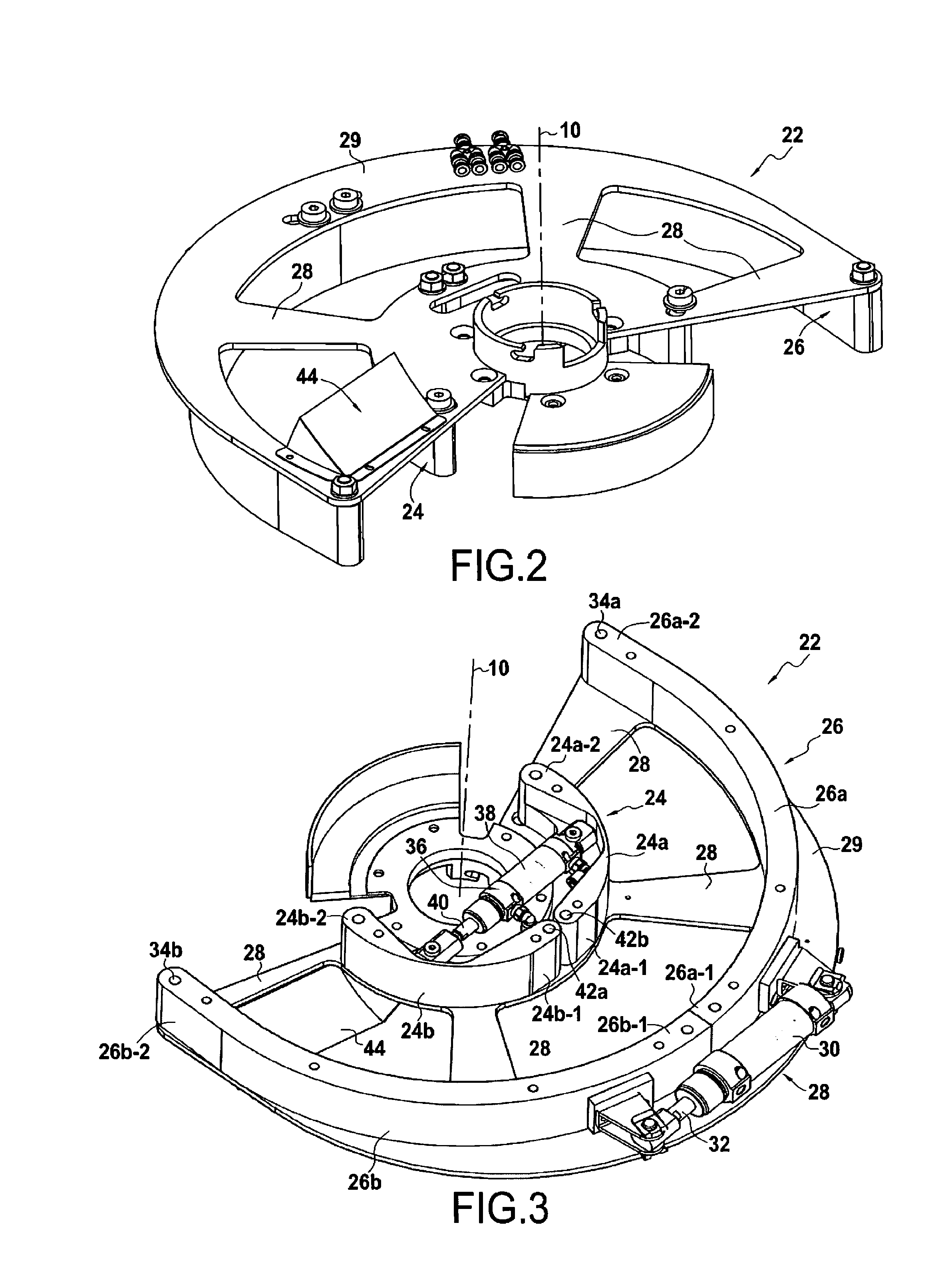
[0019] FIGS. 2 and 3 are perspective views, respectively from above and from below, of the FIG. 1 guide tooling.
DETAILED DESCRIPTION OF THE INVENTION
[0020] FIG. 1 shows a circular needling machine 2 for needling a textile structure, or annular preform, made from a helical fiber sheet (or strip).
[0021] Typically, and as described in publication EP 2 339 055, the needling machine 2 has a feed table 4 for feeding fiber sheets for needling, which feed table is located above a needling table 6.
[0022] By way of illustration, the feed table 4 for feeding fiber sheets for needling may comprise a circular conveyor 8 centered on a vertical axis 10 and having a fiber sheet 12 for needling placed thereon. More precisely, the fiber sheet may be wound as a plurality of turns about the vertical axis 10 and may be driven in rotation about the vertical axis by the circular conveyor 8.
[0023] Under the circular conveyor 8, the feed table 4 leads to a straight chute 14 that extends vertically between the circular conveyor and the needling table 6. The function of this chute is to take up the sheet 12 as it is unwound from the conveyor and to guide it vertically towards the needling table.
[0024] The fiber sheet is taken onto a support platform 16 of the needling table 6 and is driven in rotation about the vertical axis 10 in the same direction of rotation as the circular conveyor so as to pass under a needling head 18, which head is driven with vertical reciprocating motion by conventional drive means 19.
[0025] For this purpose, the rotary drive means for the fiber sheet may comprise a plurality of pairs of rollers 20 that are angularly spaced apart from one another. Each pair of rollers 20 typically comprises a conical roller 20a forming a presser roller in continuous contact with the fiber sheet, and a conical backing roller 20b arranged in an opening in the support platform of the needling table and facing the presser roller 20a so as to sandwich the fiber sheet between the rollers. More precisely, the support platform 16 is slotted so that the backing rollers come directly into contact with the fiber sheet placed on the platform.
[0026] The needling table 6 also has guide tooling 22 pressing on the support platform 16. This guide tooling serves to guide the fiber sheet while it is being needled.
[0027] For this purpose, in the invention and as shown in FIGS. 2 and 3, the guide tooling 22 comprises an inner guide rail 24 in the form of a circular arc centered on the vertical axis 10, and an outer guide rail 26 in the form of a circular arc arranged coaxially around the inner guide rail.
[0028] The inner and outer guide rails are connected to each other by radial reinforcement 28, thereby defining a passage for guiding the helical sheet under the needling head of the needling table. The radial reinforcement 28 is secured to a plate 29 positioned above the inner and outer guide rails.
[0029] Still in the invention, the outer guide rail 26 is made up of two outer guide rail angular sectors 26a, 26b, which are connected to each other by an outer actuator 28 positioned outside the outer guide rail and extending in a direction that is tangential thereto.
[0030] This outer actuator 28 is suitable for moving the adjacent free ends 26a-1 and 26b-1 of the two outer guide rail angular sectors 26a and 26b apart from each other so as to expand the outer guide rail.
More precisely, the outer actuator 28 has an actuator cylinder 30 that is fastened to one free end 26a-1 of one of the two outer guide rail angular sectors (specifically the outer guide rail sector 26a in FIGS. 2 and 3), and a rod 22 that is fastened to an adjacent free end 26b-1 of the other outer guide rail angular sector 26b.
[0031] Thus, when the outer actuator is actuated, its rod 32 extends from the actuator cylinder 30 so as to move apart the adjacent free ends 26a-1 and 26b-1 of the two outer guide rail angular sectors 26a and 26b. The distant free ends 26a-2 and 26b-2 of the outer guide rail sectors pivot about respective stationary pivots 34a and 34b.
[0032] Once needling has terminated, expanding the outer guide rail serves to facilitate extracting the needled fiber structure from the guide tooling 22 without exerting mechanical stress thereon, and thus without risk of damaging it.
[0033] The inner guide rail 24 is also made up of two inner guide rail angular sectors 24a and 24b, which sectors are connected together by an inner actuator 36 positioned inside the inner guide rail and extending in a direction that is tangential thereto.
[0034] This inner actuator 36 is suitable for moving towards each other the distant free ends 24a-2, 24b-2 of the two inner guide rail angular sectors 24a and 24b so as to contract the inner guide rail.
More precisely, the inner actuator 26 comprises an actuator cylinder 38 that is fastened to one of the two inner guide rail angular sectors (specifically the sector 24b of the inner guide rail in FIGS. 2 and 3), and a rod 40 that is fastened to the other inner guide rail angular sector 24b.
[0035] Thus, when the inner actuator is actuated, its rod 40 enters into the actuator cylinder 38 so as to move the distant free ends 24a-2 and 24b-2 of the inner guide rail angular sectors towards each other so as to contract the inner guide rail. The adjacent free ends 24a-1 and 24b-1 of the inner guide rail angular sectors pivot about respective stationary pivots 42a, 42b.
[0036] Once needling has terminated, contracting the inner guide rail 24 serves likewise to facilitate extracting the needled fiber structure from the guide tooling without exerting mechanical stress thereon, and thus without risk of damaging it. By expanding the outside diameter and contracting the inside diameter of the guide tooling, extraction of the needled fiber structure is made considerably easier.
[0037] In an advantageous arrangement, the plate 29 to which the radial reinforcement 28 of the guide tooling 22 is secured includes a deflector 44 for guiding the fiber sheet from the outlet of the chute 14 (FIG. 1) towards the passage defined by the outer and inner guide rails of the guide platform.
[0038] It should be observed that the needling table also includes a conical roller 46 that is arranged at the outlet from the chute 14 in association with the deflector 44. More precisely, this roller is positioned immediately above the fiber sheet as it leaves the chute in such a manner as to drive the fiber sheet before it passes under the needling head.
[0039] It should also be observed that the support platform 16 on which the guide tooling 22 rests is movable vertically under drive from motion-transmission means 48 progressively while the needling operation is taking place.
[0040] It should also be observed that the inner and outer actuators used for expanding the outside diameter and contracting the inside diameter of the guide platform may be actuators of any type (pneumatic, electrical, hydraulic, mechanical, manual, etc.).
* * * * *
D00000
D00001
D00002
XML
uspto.report is an independent third-party trademark research tool that is not affiliated, endorsed, or sponsored by the United States Patent and Trademark Office (USPTO) or any other governmental organization. The information provided by uspto.report is based on publicly available data at the time of writing and is intended for informational purposes only.
While we strive to provide accurate and up-to-date information, we do not guarantee the accuracy, completeness, reliability, or suitability of the information displayed on this site. The use of this site is at your own risk. Any reliance you place on such information is therefore strictly at your own risk.
All official trademark data, including owner information, should be verified by visiting the official USPTO website at www.uspto.gov. This site is not intended to replace professional legal advice and should not be used as a substitute for consulting with a legal professional who is knowledgeable about trademark law.