Method For Temperature-treating A Manganese Steel Intermediate Product, And Steel Intermediate Product Which Has Been Temperature-treated In A Corresponding Manner
FUREDER-KITZMULLER; Friedrich ; et al.
U.S. patent application number 16/085361 was filed with the patent office on 2019-03-07 for method for temperature-treating a manganese steel intermediate product, and steel intermediate product which has been temperature-treated in a corresponding manner. This patent application is currently assigned to VOESTALPINE STAHL GMBH. The applicant listed for this patent is VOESTALPINE STAHL GMBH. Invention is credited to Friedrich FUREDER-KITZMULLER, Daniel KRIZAN, Reinhold SCHNEIDER.
| Application Number | 20190071748 16/085361 |
| Document ID | / |
| Family ID | 55640576 |
| Filed Date | 2019-03-07 |


| United States Patent Application | 20190071748 |
| Kind Code | A1 |
| FUREDER-KITZMULLER; Friedrich ; et al. | March 7, 2019 |
METHOD FOR TEMPERATURE-TREATING A MANGANESE STEEL INTERMEDIATE PRODUCT, AND STEEL INTERMEDIATE PRODUCT WHICH HAS BEEN TEMPERATURE-TREATED IN A CORRESPONDING MANNER
Abstract
A method for temperature-treating a manganese steel intermediate product whose alloy includes: a manganese content, which lies in the following manganese range: 3 wt. %.ltoreq.Mn.ltoreq.12 wt. %, a fraction of one or more alloying elements of the group: silicon (Si), aluminum (Al), nickel (Ni), chromium (Cr), molybdenum (Mo), phosphorus (P), sulfur (S), nitrogen (N), copper (Cu), boron (B), cobalt (Co), tungsten (W), an optional carbon content (C) of less than 1 wt. %, an optional content of one or more microalloying elements, wherein the total content of the micro-alloying elements is less than 0.45 wt. %; and as a remainder an iron content (Fe) and unavoidable impurities.
| Inventors: | FUREDER-KITZMULLER; Friedrich; (Puchenau, AT) ; SCHNEIDER; Reinhold; (Wels, AT) ; KRIZAN; Daniel; (Linz, AT) | ||||||||||
| Applicant: |
|
||||||||||
|---|---|---|---|---|---|---|---|---|---|---|---|
| Assignee: | VOESTALPINE STAHL GMBH Linz AT |
||||||||||
| Family ID: | 55640576 | ||||||||||
| Appl. No.: | 16/085361 | ||||||||||
| Filed: | March 10, 2017 | ||||||||||
| PCT Filed: | March 10, 2017 | ||||||||||
| PCT NO: | PCT/EP2017/055714 | ||||||||||
| 371 Date: | September 14, 2018 |
| Current U.S. Class: | 1/1 |
| Current CPC Class: | C22C 38/04 20130101; C21D 8/0205 20130101; C21D 1/26 20130101; C22C 38/06 20130101; C21D 6/005 20130101; C21D 9/52 20130101; C21D 8/0247 20130101; C22C 38/12 20130101 |
| International Class: | C21D 9/52 20060101 C21D009/52; C22C 38/12 20060101 C22C038/12; C22C 38/06 20060101 C22C038/06; C22C 38/04 20060101 C22C038/04; C21D 8/02 20060101 C21D008/02; C21D 6/00 20060101 C21D006/00 |
Foreign Application Data
| Date | Code | Application Number |
|---|---|---|
| Mar 23, 2016 | EP | 16162073.7 |
Claims
1: Method for temperature-treating a manganese steel intermediate product whose alloy comprises: a manganese content (Mn), which lies in the following manganese range (MnB): 3 wt. %.ltoreq.Mn.ltoreq.12 wt. %, a content of one or more alloying elements of the group: silicon (Si), aluminum (Al), nickel (Ni), chromium (Cr), molybdenum (Mo), phosphorus (P), sulfur (S), nitrogen (N), copper (Cu), boron (B), tungsten (W), cobalt (Co), an optional carbon content (C) of less than 1 wt. %, an optional content of one or more microalloying elements, wherein the total content of the micro-alloying elements is less than 0.45 wt. %; and as a remainder an iron content (Fe) and unavoidable impurities, wherein the temperature-treating of the steel intermediate product comprises a first temperature treatment process (S.1) and a subsequent second temperature treatment process (S.2), characterized in that the first temperature treatment process (S.1) is a high-temperature process in which the steel intermediate product is subjected during a first holding period (.DELTA.1) to a first annealing temperature (T1) lying above a critical temperature limit (T.sub.KG), which is defined as follows: T.sub.KG=(856-S.sub.K*manganese content) degrees Celsius, wherein S.sub.K is a slope value, and wherein said slope value S.sub.K=7.83.+-.10%, preferably S.sub.K=7.83, the second temperature treatment process (S.2) is an annealing process in which the steel intermediate product is subjected to a second annealing temperature (T2) which is lower than the first annealing temperature (T1).
2: Method according to claim 1, characterized in that the first annealing temperature (T1) in said manganese range (MnB) has a dependence defined as follows: T.sub.1.apprxeq.(866-S.sub.K*manganese content) degrees Celsius.
3: Method according to claim 1, characterized in that the first holding period (.DELTA.1) is at least 10 seconds and preferably between 10 seconds and 6000 minutes.
4: Method according to claim 1, characterized in that the second annealing temperature (T2) is in the range between the temperatures A.sub.1 and .DELTA..sub.3, wherein A.sub.1 is the start temperature of austenitization and A.sub.3 is the start temperature of full austenitization.
5: Method according to claim 1, characterized in that the second annealing temperature (T2) is in the range of 630.degree. C. to 675.degree. C.
6: Method according to claim 1, characterized in that within the scope of the second temperature treatment process (S.2), the second annealing temperature (T2) is held during a second holding period (.DELTA.2) of at least 10 seconds.
7: Method according to claim 1, characterized in that the second temperature treatment process (S.2), including a heating process (E2) of the steel intermediate product, the holding (H2) of the second annealing temperature (T2) and a cooling process (A2) of the steel intermediate product, takes less than 6000 minutes and preferably less than 5000 minutes.
8: Method according to claim 1, characterized in that the content of the one or more alloying elements is in the following range: silicon (Si) .ltoreq.3 wt. %, and preferably .ltoreq.2 wt. %, aluminum (Al) .ltoreq.8 wt. %, and preferably .ltoreq.6 wt. %, nickel (Ni) .ltoreq.2 wt. %, and preferably .ltoreq.1 wt. %, chromium (Cr) .ltoreq.2 wt. %, and preferably .ltoreq.0.5 wt. %, molybdenum (Mo) .ltoreq.0.5 wt. %, and preferably .ltoreq.0.25 wt. %, phosphorus (P) .ltoreq.0.05 wt. %, and preferably .ltoreq.0.025 wt. %, sulfur (S) .ltoreq.0.03 wt. %, and preferably .ltoreq.0.01 wt. %, nitrogen (N) .ltoreq.0.05 wt. %, and preferably .ltoreq.0.025 wt. %, copper (Cu) .ltoreq.1 wt. %, and preferably .ltoreq.0.5 wt. %, boron (B) .ltoreq.0.005 wt. %, and preferably .ltoreq.0.0035 wt. %, tungsten (W) .ltoreq.1 wt. %, and preferably .ltoreq.0.5 wt. %, cobalt (Co) .ltoreq.2 wt. %, and preferably .ltoreq.1 wt. %.
9: Method according to claim 1, characterized in that the micro-alloying elements are elements of the group: titanium (Ti), niobium (Nb), vanadium (V).
10: Method according to claim 1, characterized in that the first temperature treatment process (S.1) concerns a process which is carried out in a continuous strip plant or in a discontinuously operating plant.
11: Method according to claim 1, characterized in that the second temperature treatment process (S.2) is a process which is carried out in a continuous strip plant or in a discontinuously operating plant, wherein the steel intermediate product in this plant is exposed in the annealing process to a protective gas atmosphere.
12: Method according to claim 11, characterized in that a hood-type annealing device is used as a discontinuously operating plant.
13: Method according to claim 1, characterized in that the steel intermediate product is subjected to a skin-pass rolling process in a step which is downstream of the second temperature treatment process (S.2), wherein this skin-pass rolling process is primarily directed to condition the surface of the steel intermediate product.
14: Method according to claim 1, characterized in that the first temperature treatment process (S.1) is carried out during a hot rolling process, wherein said hot rolling process is carried out with a rolling end temperature which lies in the range above the critical temperature limit (T.sub.KG).
15: Steel intermediate product which has been heat-treated according to a method of claim 1, characterized in that it has a Luders strain (A.sub.L) which is less than 3% and preferably less than 1%.
16: Steel intermediate product according to claim 15, characterized in that a Luders strain (A.sub.L) of less than 3% on the steel intermediate product is measurable before the steel intermediate product was subjected to a subsequent skin-pass rolling process.
17: Steel intermediate product according to claim 15, characterized in that, due to a reduced Luders strain (A.sub.L), in comparison to the reduction of Luders strain with skin-pass rolling, it has a greater useful technical elongation.
Description
[0001] The present invention relates to a method of temperature treating a manganese steel intermediate product. It also relates to a specific alloy of a manganese steel intermediate product, which is temperature-treated by a special process to achieve a significantly reduced Luders strain. This application claims the priority of European Patent Application Number EP 16 162 073.7, filed on 23 Mar. 2016.
[0002] Both the composition and the alloy, respectively, as well as the heat treatment in the manufacturing process have a significant influence on the properties of steel products.
[0003] It is known that in the course of a heat treatment, the warming-up, holding and cooling can have an influence on the final structure of a steel product. Furthermore, as already indicated, the alloy composition of the steel product obviously also plays a major role. The thermodynamic and material-technical relationships in alloyed steels are very complex and depend on many parameters.
[0004] It has been shown that a combination of different phases in the microstructure of a steel product can influence the mechanical properties and the deformability.
[0005] Depending on the specific requirement profile, different steels are used.
[0006] An important component of today's new steel alloys is manganese (Mn). These are so-called medium-manganese steels. The manganese content in weight percent (wt. %) is often in the range between 3 and 12. Due to its microstructure, a medium-manganese steel has a high combination of tensile strength and elongation. Typical applications in the automotive industry are complex safety-relevant deep-drawn components.
[0007] In FIG. 1, a classical, highly schematic diagram is shown, in which the elongation at break A.sub.80 (also known as total elongation) is plotted in percent over the tensile strength in MPa. The tensile strength is abbreviated here with R.sub.m. The diagram of FIG. 1 gives an overview of the strength classes of currently used steel materials for the automotive industry. In general, the following statement applies: the higher the tensile strength R.sub.m of a steel alloy, the lower the total elongation A.sub.80 of this alloy. In simple terms, it can be stated that the total elongation A.sub.80 decreases with increasing tensile strength R.sub.m and vice versa. It is therefore necessary to find an optimal compromise between the total elongation A.sub.80 and the tensile strength R.sub.m for each application.
[0008] In the automotive sector, one works with a whole range of different steel alloys, each of which has been optimized specifically for their particular application area on the vehicle. For interior and exterior panels, structural parts and bumpers, alloys are used which have good energy absorption. Steel panels for the outer skin of a vehicle are relatively "soft" and have for example a tensile strength R.sub.m of approx. 300 MPa and a good total elongation A.sub.80>30%. The steel alloys of safety-relevant components, for example, have a tensile strength R.sub.m in the range between 600 and 1000 MPa. For example, the TRIP (transformation-induced plasticity) steels (reference numeral 1 in FIG. 1) are very well suited for this purpose.
[0009] For steel barriers (e.g. for side impact protection), which should prevent the ingress of vehicle parts in an accident, steel alloys are used which have a high tensile strength R.sub.m of usually more than 1000 MPa. In this case, for example, the new generation of higher-strength AHSS (Advanced High-Strength Steels) steels is suitable (reference numeral 2 in FIG. 1). This category includes the TBF (Trip Bainitic Ferrite) steels and the Q&P (Quenching & Partitioning) steels. These high-strength AHSS steels have, for example, a manganese content in the range between 1.2 and 3 wt. % and a carbon content C which is between 0.05 and 0.25 wt. %.
[0010] In the area designated by the reference numeral 3 in FIG. 1, the already mentioned medium-manganese steels are schematically summarized. The area designated by the reference numeral 3 comprises medium-manganese steels having an Mn content of between 3 and 12 wt. % and a carbon content of .ltoreq.1 wt. %.
[0011] Today's medium manganese steels have a pronounced yield strength due to their ultra-fine grain (typically .ltoreq.1 .mu.m), which is clearly visible in the tensile test. An exemplary tensile curve 4 (also called stress-strain curve) is shown in FIG. 2. In FIG. 2, the tension .sigma. (in MPa) is plotted over the elongation .epsilon. (in %). The tensile curve 4 shows an intermediate maximum 5, which is referred to as the upper yield strength (R.sub.eH), followed by a plateau 6. In the region of the lower yield strength (R.sub.eL), the plateau 6 changes into a rising curve region. The "length" of the plateau 6 is referred to as Luders strain (A.sub.L), as shown in FIG. 2. A steel product with such a pronounced yield strength can form undesirable Luders bands (stretcher-strainer marks) on the surface of the components for the automobile industry. Therefore, the pronounced yield strength typically needs to be reduced by a re-rolling process. The aftertreatment in a corresponding re-rolling plant (usually with a skin-pass mill) is also referred to as skin-pass rolling.
[0012] The energetic and technical effort for skin-pass rolling is sometimes quite high. In addition, this process leads to a reduction of the usable elongation.
[0013] It is therefore the object to develop a method for the production of manganese steel intermediate products in which the Luders strain is less pronounced. Preferably, the manganese steel intermediate products should have no (measurable) Luders strain.
[0014] Investigations on numerous alloy compositions of medium-manganese steels have shown that there is a correlation between the original austenite grain size of these steels and the Luders strain. This means that the original austenite grain size has an influence on the mechanical properties of these steels. In general, it can be postulated that the Luders strain behaves inversely proportional to the original austenite grain size.
[0015] The partial object of the invention is thus to find an alloy composition and a process for temperature treatment in order to increase the original austenite grain size and to manifest the increased austenite grains in the structure of the medium-manganese steels. Unlike the prior art (see WO2014095082 A1, for example), which concerns the provision of ultrafine structures (with an ultrafine grain having an average particle size of about 1 .mu.m), the invention aims in a different direction. In addition, in the exemplified patent application WO2014095082 A1, a double annealing process is used, which works with other temperatures and process procedures. Steel products made by the method of WO2014095082A1 have a pronounced yield strength.
[0016] In accordance with the invention, there is provided a particularly suitable manganese steel alloy and an optimized process for temperature-treating a manganese steel intermediate product.
[0017] The manganese steel alloy of the invention comprises: [0018] a manganese content (Mn) which is in the following manganese range 3 wt. %.ltoreq.Mn.ltoreq.12 wt. %, [0019] a content of one or more alloying elements of the group: silicon (Si), aluminum (Al), nickel (Ni), chromium (Cr), molybdenum (Mo), phosphorus (P), sulfur (S), nitrogen (N), Copper (Cu), boron (B), cobalt (Co), tungsten (W), [0020] an optional carbon content (C) of less than 1 wt. %, [0021] an optional content of one or more micro-alloying elements such as: titanium (Ti), niobium (Nb) and vanadium (V), wherein the total content of microalloying elements is less than 0.45 wt. %, and [0022] the remainder being an iron content (Fe) and unavoidable impurities.
[0023] The manganese steel intermediate products which have been produced from a melt of this manganese steel alloy are subjected within the scope of a temperature treatment according to the invention to a first temperature treatment process and a subsequent second temperature treatment process.
[0024] The first temperature treatment process is a high-temperature process in which the steel intermediate product is subjected during a first holding period to a first annealing temperature which is above a critical temperature limit (referred to as T.sub.KG), wherein this critical temperature limit (T.sub.KG) is defined as follows: T.sub.KG.gtoreq.(856-S.sub.K*manganese content) degrees Celsius, and wherein S.sub.K is a slope value.
[0025] The aforementioned formula, which serves as a definition of the critical temperature limit (T.sub.KG), states that the critical temperature limit (T.sub.KG) decreases in the manganese range mentioned with increasing manganese content.
[0026] The aforementioned slope value is preferably defined in all embodiments as follows: S.sub.K=7.83.+-.10% and particularly preferably at S.sub.K=7.83.
[0027] The second temperature treatment process is an annealing process in which the steel intermediate product is subjected to a second annealing temperature T2, which is in each case lower than the first annealing temperature T1.
[0028] Preferably, the first annealing temperature T1 shows in all embodiments a dependence on said manganese range of the alloy, which is defined as follows: T1.gtoreq.T.sub.KG.
[0029] Particularly preferred are embodiments of the invention at a critical temperature T.sub.K.gtoreq.(866-S.sub.K*manganese content) degrees Celsius, where the following applies: S.sub.K=7.83.+-.10%.
[0030] Preferably, the first holding period is at least 10 seconds in all embodiments. Particularly preferably, the first holding period in all embodiments is between 10 seconds and 7000 minutes.
[0031] Preferably, the second annealing temperature T2 is in all embodiments in the range between the temperatures A.sub.1 and A.sub.3.
[0032] Advantageous results are obtained if the second temperature treatment process, including the heating of the steel intermediate product, the holding the second annealing temperature and the cooling of the steel intermediate product, takes less than 6000 minutes. Preferably, this total time is even less than 5000 minutes.
[0033] The invention can be applied particularly advantageously to alloys in which the proportion of the one or more alloying elements lies in the following range: [0034] silicon (Si) .ltoreq.3 wt. %, and preferably .ltoreq.2 wt. %, [0035] aluminum (Al) .ltoreq.8 wt. %, and preferably .ltoreq.6 wt. %, [0036] nickel (Ni) .ltoreq.2 wt. %, and preferably .ltoreq.1 wt. %, [0037] chromium (Cr) .ltoreq.2 wt. %, and preferably .ltoreq.0.5 wt. %, [0038] molybdenum (Mo) .ltoreq.0.5 wt. %, and preferably .ltoreq.0.25 wt. %, [0039] phosphorus (P) .ltoreq.0.05 wt. %, and preferably .ltoreq.0.025 wt. %, [0040] sulfur (S) .ltoreq.0.03 wt. %, and preferably .ltoreq.0.01 wt. %, [0041] nitrogen (N) .ltoreq.0.05 wt. %, and preferably .ltoreq.0.025 wt. %, [0042] copper (Cu) .ltoreq.1 wt. %, and preferably .ltoreq.0.5 wt. %, [0043] boron (B) .ltoreq.0.005 wt. %, and preferably .ltoreq.0.0035 wt. %, [0044] tungsten (W) .ltoreq.1 wt. %, and preferably .ltoreq.0.5 wt. %, [0045] cobalt (Co) .ltoreq.2 wt. %, and preferably .ltoreq.1 wt. %.
[0046] Advantageous results are shown in all embodiments in which elements of the following group are used as micro-alloying elements: titanium (Ti), niobium (Nb), vanadium (V).
[0047] For the first time, the invention makes it possible to provide steel intermediate products having a Luders strain A.sub.L which is less than 3% and preferably less than 1%.
[0048] At the same time, the steel intermediate products of the invention preferably have an average primary austenite grain size greater than 3 .mu.m in all embodiments.
[0049] The alloy of the steel intermediate products of the invention preferably has an average manganese content according to the invention, which means that the manganese content is in the range of 3 wt. %.ltoreq.Mn.ltoreq.12 wt. %. Preferably, the manganese content in all embodiments is in the range 3.5 wt. %.ltoreq.Mn.ltoreq.8.5 wt. %.
[0050] The carbon content of the steel products of the invention is generally rather low. In addition, the carbon content is optional in all embodiments. That is, the carbon content is in the range C 1 wt. % in the invention. Embodiments in which the carbon content is in one of the following ranges are particularly preferred
[0051] a) 0.01.ltoreq.C.ltoreq.0.8 wt. %, or
[0052] b) 0.05.ltoreq.C.ltoreq.0.3 wt. %.
[0053] In a preferred method of the invention, the first temperature treatment process is carried out in a continuous strip plant (annealing plant). This process is also known as continuous annealing. Or another possibility is a discontinuous heat treatment (hood-type annealing) of the steel intermediate product.
[0054] If the temperature treatment of a hot strip is concerned, the first temperature treatment of the invention can also be carried out by a special temperature control during hot rolling. With this special temperature control, care is taken to ensure that the rolling end temperature of the hot strip during hot rolling is in the range above the critical temperature limit T.sub.KG.
[0055] In a preferred method of the invention, the second temperature treatment process is carried out in a discontinuously operating plant, wherein the steel intermediate product is subjected to the annealing process in this plant in a protective gas atmosphere. This process is preferably carried out in a hood-type annealing plant. However, the second temperature treatment process can also be carried out in all embodiments in a continuous strip plant (annealing plant) or in a hot-dip galvanizing plant.
[0056] The steel intermediate product of all embodiments may optionally be subjected to a skin-pass rolling process, which is primarily directed to conditioning the surface of the steel intermediate product. A more intensive skin-pass rolling is not required because the steel intermediate products of the invention have a low Luders strain.
[0057] Thus, with the invention, the degree of skin-pass rolling can be reduced or completely avoided.
[0058] It is an advantage of the invention that steel intermediate products can be made which have a Luders strain which is less than 3% and which is preferably less than 1%.
[0059] It is an advantage of the invention that steel intermediate products can be produced which have a tensile strength R.sub.m (also called minimum strength) which is greater than 490 MPa.
[0060] It is an advantage of the invention that steel intermediate products can be produced which as a result of the reduced Luders strain have a (minimum) total elongation (A.sub.80) which is greater than 10%.
[0061] It is an advantage of the invention that the steel intermediate products have an increased technically usable elongation due to the reduced Luders strain.
[0062] The invention can be used, for example, to provide cold rolled steel products in the form of cold rolled flat products (e.g. coils). The invention can also be used, for example, to produce thin sheets or also wires and wire products.
[0063] The invention can also be used to provide hot strip steel products.
[0064] Further advantageous embodiments of the invention form the subject matters of the dependent claims.
DRAWINGS
[0065] Embodiments of the invention will be described in more detail below with reference to the drawings.
[0066] FIG. 1 shows a highly schematic diagram in which the (minimum) total elongation (A.sub.80) is plotted in percent versus the tensile strength (R.sub.m) in MPa for various steels for the automotive industry;
[0067] FIG. 2 shows a schematic stress-strain diagram of a steel product, which has a pronounced yield strength (Luders strain A.sub.L);
[0068] FIG. 3 shows a schematic diagram showing the two temperature treatment processes;
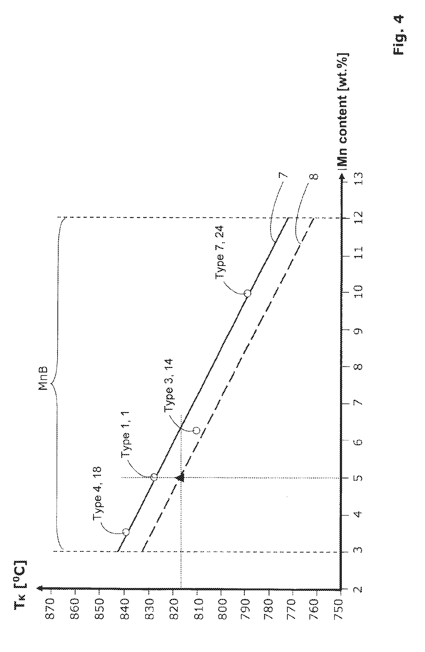
[0069] FIG. 4 shows in the form of a schematic diagram the critical Temperature T.sub.K and the course of the corresponding critical temperature limit T.sub.KG;
[0070] FIG. 5 shows a schematic diagram, which on the one hand shows the Luders strain A.sub.L in percent and on the other hand the average original austenite grain size (D.sub.UAK M) as a function of the first annealing temperature T1, wherein, in this diagram, the corresponding curves of two different samples are shown;
[0071] FIG. 6 shows a schematic diagram showing the tension .sigma. in MPa as a function of elongation .epsilon. in % (analogous to FIG. 2), wherein four identical alloys were subjected in this case to four different temperature treatment processes.
DETAILED DESCRIPTION
[0072] According to the invention, steel products or steel intermediate products are concerned which are characterized by a special microstructure constellation and properties.
[0073] In the following, the term "intermediate steel products" is sometimes used when it is intended to stress that the finished steel product is not concerned but instead a preliminary or intermediate product in a multi-stage production process. The starting point for such manufacturing processes is usually a melt. In the following, the alloy composition of the melt is given, since on this side of the manufacturing process, it is possible to influence the alloy composition relatively accurately (for example, by adding components such as alloying elements and optional micro-alloying elements). The alloy composition of the steel intermediate product usually deviates only insignificantly from the alloy composition of the melt.
[0074] Quantities or content information are given here largely in weight percent (in short wt. %), unless stated otherwise. If information is provided on the composition of the alloy, or the steel product, respectively, then the composition includes, in addition to the explicitly listed materials or substances, iron (Fe) as basic material and so-called unavoidable impurities that always occur in the molten bath and that also show up in the resulting steel intermediate product. All statements in wt. % must always be added to 100 wt. % and all % by volume must always be added to 100% of the total volume.
[0075] In addition to the special combination of alloying elements, a specially optimized process for temperature treatment is used. A corresponding diagram is shown in FIG. 3 and will be explained in more detail below.
[0076] The temperature treatment of the steel intermediate product comprises a first temperature treatment process S.1 and a subsequent second temperature treatment process S.2. These two temperature treatment processes S.1 and S.2 are shown in FIG. 3 in two temperature-time diagrams shown next to one another.
[0077] The first temperature treatment process S.1 is a high-temperature process in which the steel intermediate product is subjected to a first annealing temperature T1 during a first holding period .DELTA.1 (this step is also referred to as holding H1). The annealing temperature T1 lies above a critical temperature limit T.sub.KG during the holding H1.
[0078] The course of this critical temperature limit T.sub.KG is dependent (inter alia) on the manganese content Mn of the alloy of the manganese steel intermediate product, as determined by numerous examinations. In FIG. 4, the critical temperature T.sub.K (represented by the straight line 7) and the course of the corresponding critical temperature limit T.sub.KG (represented by the straight line 8) are shown.
[0079] On the horizontal axis, the manganese range MnB is plotted in percent by weight. As already mentioned, the invention gives excellent results especially with a manganese content in the following manganese range MnB: 3 wt. %.ltoreq.Mn.ltoreq.12 wt. %. This manganese range MnB is shown in FIG. 4 by two vertical boundary lines at Mn=3 wt. % and Mn=12 wt. %.
[0080] FIG. 4 shows by way of example the measurement results of four samples on the basis of small circle symbols. Further details on these four exemplary samples and on further samples of the invention are shown in Tables 1 and 2.
TABLE-US-00001 TABLE 1 Alloy C Mn Al Nb S.1 S.2 Type 1 0.096 5.08 Cont. annealing Hood Type 2 0.097 5.13 0.09 Cont. annealing Hood Type 3 0.100 6.38 Cont. annealing Hood Type 4 0.106 3.53 Cont. annealing Hood Type 5 0.110 3.56 0.095 Cont. annealing Hood Type 6 0.148 7.73 2.09 Cont. annealing Cont. annealing Type 7 0.098 9.95 Cont. annealing Hood
TABLE-US-00002 TABLE 2 No Alloy T1, .degree. C. T2, .degree. C. R.sub.p0.2 or R.sub.eL MPa R.sub.m, MPa A.sub.80, % RA, vol. % A.sub.L, % D.sub.UAK M, .mu.m 1 Type 1 830 660 550 850 27.1 20.9 2.1 5 2 Type 1 875 660 551 878 28.7 20.1 0 13.7 3 Type 1 900 660 561 890 28.3 21.3 0 15.5 4 Type 1 920 660 561 898 28.5 21.1 0 18 5 Type 1 935 660 559 894 30.2 19.8 0 20 6 Type 1 950 660 522 820 30.7 21.4 0 22 7 Type 1 1100 660 560 852 27.9 21.2 0 45.7 8 Type 2 980 660 632 928 23.4 21.4 2.8 8.5 9 Type 2 1000 660 640 928 23.7 21.9 2.6 9.5 10 Type 2 1025 660 646 931 22.9 22.7 2.2 11.1 11 Type 2 1050 660 643 929 23.4 19.2 2 12 12 Type 2 1075 660 673 962 24.3 19.9 0 13.5 13 Type 2 1100 660 642 898 22.9 22.5 0 14.7 14 Type 3 810 640 635 901 33.3 32.1 2.6 6.4 15 Type 3 850 640 615 903 35.8 32.6 1.8 9.4 16 Type 3 900 640 595 898 36.1 32.2 0 13.8 17 Type 3 950 640 552 893 37 31.8 0 18.9 18 Type 4 840 660 413 559 18.5 6.4 2.2 6 19 Type 4 950 660 391 641 18.5 6.5 1.5 15 20 Type 5 950 630 352 543 19.2 2.7 1.2 7 21 Type 5 1025 630 432 631 17.1 4.9 0 11 22 Type 5 1100 630 623 710 11.8 4.1 0 15 23 Type 6 900 675 829 1083 19.8 20.3 2.3 4.86 24 Type 7 790 630 601 1145 25.2 39.1 2.2 4.8 25 Type 7 900 630 588 1130 28.1 37.2 0 8.8 26 Type 7 950 630 582 1122 29.3 34.6 0 12.9
[0081] The alloy composition of the respective type is shown in Table 1, wherein only the essential alloying components are mentioned here. For each type, there are a number of embodiments that have been tested. The corresponding examples are numbered in the left column in Table 2 with the numbers 1 to 26.
[0082] In FIG. 4, the following four samples are shown by the circle symbols mentioned: Type 4, 18; Type 1, 1; Type 3, 14 and Type 7, 24 (the designation Type 4, 18 represents, for example, the alloy composition of Type 4, Example No. 18).
[0083] If the circle symbols of FIG. 4, or the measurement results respectively, are interpolated by a straight line, then a straight line 7 descending constantly results, as shown in FIG. 4. This straight line 7 can be circumscribed by the following equation (1), wherein T.sub.K is given in degrees Celsius:
T.sub.K=(866-S.sub.K*manganese content) (1)
[0084] The absolute value 866 in degrees Celsius defines the intersection with the vertical axis and the value S.sub.K defines the slope. S.sub.K is therefore also called the slope value.
[0085] The examinations have shown that the slope value S.sub.K is preferably 7.83.+-.10% in all embodiments.
[0086] In addition, it could be shown that the critical temperature T.sub.K for alloy compositions according to the invention always lies above a lower critical temperature limit T.sub.KG. This lower critical temperature limit T.sub.KG is shown in FIG. 4 as a straight line 8.
[0087] This straight line 8 can be circumscribed by the following equation (2), wherein T.sub.KG is given in degrees Celsius:
T.sub.KG=(856-S.sub.K*manganese content) (2)
[0088] The straight line 8 lies parallel to the straight line 7.
[0089] The following condition can be postulated: For steel alloys of the manganese steel intermediate product, as already defined, the first annealing temperature T1 must always be above the lower critical temperature limit T.sub.KG to ensure that a manganese steel intermediate product is obtained in which the Luders strain A.sub.L is less than 3%.
[0090] It could be shown that also the second temperature treatment process S.2 has an influence on the Luders strain. In order to maintain the grain size of the austenite grains in the structure, the second annealing temperature T2 must be lower than the first annealing temperature T1 in any case. Since the first annealing temperature T1 is always above the lower critical temperature limit T.sub.KG, it can be concluded that the second annealing temperature T2 should preferably be below the lower critical temperature limit T.sub.KG.
[0091] It can be seen from the schematic example of FIG. 3 that the first annealing temperature T1 is above the temperature limit T.sub.KG and that the second annealing temperature T2 is in the range between A.sub.1 and A.sub.3. The second temperature treatment S.2 is also referred to in this case as intercritical annealing.
[0092] The first holding period .DELTA.1 is preferably at least 10 seconds in all embodiments, and preferably between 10 seconds and 6000 minutes.
[0093] The second holding period .DELTA.2 is at least 10 seconds in all embodiments. In FIG. 3, the two holding periods .DELTA.1 and .DELTA.2 are shown only by way of example. The interval between the first temperature treatment process S.1 and the second temperature treatment process S.2 can be selected as needed. Typically, the second temperature treatment process S.2 is performed shortly after the first temperature treatment process S.1.
[0094] Preferred embodiments are those in which the first temperature treatment process S.1, including the heating E1 of the steel intermediate product, the holding H1 of the first annealing temperature T1 and the cooling Ab1 of the steel intermediate product takes less than 7000 minutes.
[0095] Preferred embodiments are those in which the second temperature treatment process S.2, including the heating E2 of the intermediate steel product, the holding H2 of the second annealing temperature T2 and the cooling Ab2 of the steel intermediate product takes less than 6000 minutes and preferably less than 5000 minutes.
[0096] Furthermore, it could be shown that the significant reduction of Luders strain A.sub.L is independent of whether the first temperature treatment process S.1 and/or the second temperature treatment process S.2 is/are carried out in a continuous strip plant (for example in a continuous plant) or in a discontinuous plant (for example in a hood-type annealer).
[0097] The invention can be applied to both cold strip intermediate products and hot strip intermediate products. In both cases, a significant reduction in Luders strain A.sub.L can be seen.
[0098] Increasing the first annealing temperature T1 to a value above the critical temperature limit T.sub.KG clearly leads to an increase in the average original austenite grain size and to a significant reduction in the Luders strain A.sub.L.
[0099] FIG. 5 shows both the reduction of Luders strain A.sub.L in percent and the dependence of the average original austenite grain size (D.sub.UAK M) in .mu.m with increasing annealing temperature T1 for two exemplary samples of Type 1 and Type 2 (see also Table 1), as follows.
[0100] Chemical composition of alloy samples of Type 1 without microalloying:
Mn=5.08 wt. %,
C=0.096 wt. %,
[0101] the remainder iron Fe and unavoidable impurities.
[0102] Chemical composition of alloy samples of Type 2 with microalloying:
Mn=5.13 wt. %,
C=0.097 wt. %,
Nb=0.90 wt. %,
[0103] the remainder iron Fe and unavoidable impurities.
[0104] It can be seen from FIG. 5 that in the examined alloy composition of Type 1 (represented by the curve 9), the critical temperature limit T.sub.KG is .about.820.degree. C. when it is desired to obtain a Luders strain for this alloy composition of Type 1 which is smaller than 3%. The curve 10 shows the associated course of the average original austenite grain size D.sub.UAK M 1, as a function of the temperature T1. For the example Type 1, a grain size for this is obtained with >3 .mu.m.
[0105] It can be seen from FIG. 5 that in the examined alloy composition of Type 2 (represented by the curve 11), the critical temperature limit T.sub.KG2 is .about.970.degree. C. when it is desired to obtain a Luders strain for this alloy composition of Type 2 which is smaller than 3%. The curve 12 shows the corresponding curve of the average original austenite grain size (D.sub.UAK M) as a function of the temperature T1. For the example Type 2, a grain size for this results with >8 .mu.m. The micro-alloying element niobium (Nb) has a recognizable influence, which is expressed as a shift of T.sub.KG2 (compared to T.sub.KG1) to a higher critical temperature for A.sub.L<3%.
[0106] The curves 10 and 12 in FIG. 5 show that the original austenite grain size increases with increasing temperature T1.
[0107] On the basis of the above equation (2), for the alloy compositions of Type 1, the lower temperature limit T.sub.KG1 can be determined as follows:
T.sub.KG1=(856-7.83*5)=.about.817.degree. C. (2.1)
[0108] In FIG. 5, the corresponding lower temperature limit T.sub.KG1 is shown as a dashed vertical line. It can be seen that the alloy compositions of the Type 1 have an average grain size from an annealing temperature T1>T.sub.KG1 on which is >3 .mu.m. The lower temperature limit T.sub.KG1 is indicated in FIG. 4 by a small black triangle.
[0109] On the basis of the equation (2), for the alloy compositions of Type 2, the lower critical temperature limit T.sub.KG2 can be determined as follows:
T.sub.KG2=(856-7.83*5)=.about.817.degree. C.=T.sub.KG1 (2.2)
[0110] For alloy compositions having an Nb content, the micro-alloy leads to an increase in the critical temperature limit T.sub.KG. In FIG. 5, it can be seen, using the example of Type 2, that the critical temperature limit T.sub.KG2 is approx. 150.degree. C. higher than for the alloy compositions of Type 1. In FIG. 5, the corresponding effective lower critical temperature limit T*.sub.KG2 is shown as a dashed vertical line. In the case of alloy compositions of Type 2, the annealing temperature must be T1>T*.sub.KG2=T.sub.KG2+150.degree. C. The resulting average original austenitic grain size is .gtoreq.8 .mu.m in this case.
[0111] FIG. 6 shows a schematic diagram indicating the tension .sigma. in MPa as a function of the elongation .epsilon. in %. The representation of FIG. 6 is to be compared with the representation of FIG. 2, wherein FIG. 6 shows only a small section.
[0112] Specifically, four identical samples (Type 3 alloys of Table 1) were compared here. The Type 3 alloys also meet the requirements of the invention. All four samples were each subjected to a first temperature treatment process S.1 and a subsequent second temperature treatment process S.2. All process parameters were identical, except that in the first temperature treatment process S.1, the first annealing temperature T1 was varied as follows (see column 2 of the following Table 3):
TABLE-US-00003 TABLE 3 T1 T2 Alloy [.degree. C.] [.degree. C.] Curve Type 3 810 640 13.1 Type 3 850 640 13.2 Type 3 900 640 13.3 Type 3 950 640 13.4
[0113] The alloys of Type 3 had the following main composition in these experiments:
Mn=6.38 wt. %,
C=0.1 wt. %,
[0114] remaining iron Fe and unavoidable impurities.
[0115] The solid curve 13.1 of FIG. 6 (Type 3, 14 of Table 2) shows a clearly visible pronounced yield strength and has a Luders strain of A.sub.L.about.2.6%. The temperature T1 here was 810.degree. C., which for a Type 3 alloy and a slope value S.sub.K=7.83 is slightly above the lower critical temperature limit T.sub.KG.
[0116] The curve 13.2 represents another exemplary sample (Type 3, 15 of Table 2) of Type 3, wherein here the yield strength is still slightly pronounced.
[0117] Another identical sample (see the dash-dotted curve 13.3 in FIG. 6) was temperature-treated at a higher temperature T1=900.degree. C. (i.e. at T1>T.sub.KG) and no pronounced yield strength is visible any more. This concerns Type 3, 16 of Table 2.
[0118] The curve 13.4 represents a further exemplary sample of the Type 3, wherein in this case too no pronounced yield strength is visible any more. This concerns Type 3, 17 of Table 2.
[0119] When considering the manganese steel intermediate products of the invention in connection with FIG. 1, the corresponding measured values (e.g. for the alloy compositions of Type 1, Type 2 and Type 3) lie in the range of about 700 to 1000 MPa and with a total elongation A.sub.80 in the range of about 20 to 40%.
TABLE-US-00004 List of reference numerals TRIP steels 1 Q&P and TBF steels 2 Medium-manganese steels 3 Tensile curve 4 Intermediate maximum 5 Plateau 6 Straight line 7 Straight line 8 Curve 9 Curve 10 Curve 11 Curve 12 Curves 13.1, 13.2, 13.3, 13.4 Start temperature of austenitization A.sub.1 Start temperature of full austenitization A.sub.3 Total elongation A.sub.80 Luders strain A.sub.L First cooling Ab1 Second cooling Ab2 Average original austenite grain boundary D.sub.UAK M First holding period .DELTA.1 Second holding period .DELTA.2 First heating E1 Second heating E2 Elongation .epsilon. First holding H1 Second holding H2 Manganese range MnB Residual austenite content RA Upper yield strength R.sub.eH Lower yield strength R.sub.eL Tensile strength R.sub.m 0.2% yield strength R.sub.p0.2 First temperature treatment process S.1 Second temperature treatment process S.2 Tension .sigma. Slope value S.sub.K First annealing temperature T1 Second annealing temperature T2 Critical temperature limit T.sub.KG Critical temperature limit T.sub.KG1 Critical temperature limit T.sub.KG2 Effective critical temperature limit T*.sub.KG2
* * * * *
D00001
D00002
D00003
D00004
D00005
XML
uspto.report is an independent third-party trademark research tool that is not affiliated, endorsed, or sponsored by the United States Patent and Trademark Office (USPTO) or any other governmental organization. The information provided by uspto.report is based on publicly available data at the time of writing and is intended for informational purposes only.
While we strive to provide accurate and up-to-date information, we do not guarantee the accuracy, completeness, reliability, or suitability of the information displayed on this site. The use of this site is at your own risk. Any reliance you place on such information is therefore strictly at your own risk.
All official trademark data, including owner information, should be verified by visiting the official USPTO website at www.uspto.gov. This site is not intended to replace professional legal advice and should not be used as a substitute for consulting with a legal professional who is knowledgeable about trademark law.