Hvac Fluid Conditioning System
Italia; Richmond ; et al.
U.S. patent application number 16/117895 was filed with the patent office on 2019-03-07 for hvac fluid conditioning system. This patent application is currently assigned to AC Freeflow, LLC. The applicant listed for this patent is AC Freeflow, LLC. Invention is credited to Richmond Italia, Louis Spicer.
| Application Number | 20190071331 16/117895 |
| Document ID | / |
| Family ID | 63490252 |
| Filed Date | 2019-03-07 |


| United States Patent Application | 20190071331 |
| Kind Code | A1 |
| Italia; Richmond ; et al. | March 7, 2019 |
HVAC FLUID CONDITIONING SYSTEM
Abstract
According to principles of the present inventive concepts, an HVAC fluid conditioning system comprises an inlet port configured to receive HVAC fluid from an HVAC condensation line. A conditioning system treats the HVAC fluid with a chemical or other treatment process to prevent the growth of harmful pollutants within the HVAC condensation line. The treated HVAC fluid is then released from the conditioning system through an outlet port thereof and back into the HVAC condensation line. A trap system can be provided to trap harmful gases created during the HVAC fluid treatment process.
| Inventors: | Italia; Richmond; (Dorval, CA) ; Spicer; Louis; (Sewell, NJ) | ||||||||||
| Applicant: |
|
||||||||||
|---|---|---|---|---|---|---|---|---|---|---|---|
| Assignee: | AC Freeflow, LLC Fort Lauderdale FL |
||||||||||
| Family ID: | 63490252 | ||||||||||
| Appl. No.: | 16/117895 | ||||||||||
| Filed: | August 30, 2018 |
Related U.S. Patent Documents
| Application Number | Filing Date | Patent Number | ||
|---|---|---|---|---|
| 62553253 | Sep 1, 2017 | |||
| Current U.S. Class: | 1/1 |
| Current CPC Class: | C02F 2103/023 20130101; F25B 41/003 20130101; C02F 2303/20 20130101; F25B 39/04 20130101; F24F 13/222 20130101; C02F 2307/14 20130101; C02F 1/50 20130101; C02F 1/688 20130101; F24F 2013/228 20130101; F24F 13/00 20130101 |
| International Class: | C02F 1/50 20060101 C02F001/50; C02F 1/68 20060101 C02F001/68; F24F 13/00 20060101 F24F013/00; F25B 39/04 20060101 F25B039/04; F25B 41/00 20060101 F25B041/00 |
Claims
1. An HVAC fluid conditioning system, comprising: a fluid inlet port connected to an HVAC fluid pipe to receive HVAC fluid from an HVAC system therein; a conditioning unit configured to treat the HVAC fluid with a chemical to prevent pollutant growth; and a fluid outlet port connected to an HVAC fluid pipe to deliver the treated HVAC fluid to the HVAC system.
2. An HVAC fluid conditioning system according to claim 1, further comprising: a trap system configured to trap and prevent harmful gases from the HVAC fluid conditioning system from entering the HVAC system.
3. An HVAC fluid conditioning system according to claim 1, wherein the conditioning unit comprises a chlorine tablet or rod dispenser configured to place the chlorine tablet or rod into contact with a fluid flow through the HVAC conditioning system to treat the fluid with chlorine.
4. An HVAC fluid conditioning system according to claim 3, wherein the chlorine tablet or rod dispenser comprises a tube configured to receive the chlorine tablet or rod, and said tube or pipe further having openings formed in an end thereof, wherein said openings are configured to permit the fluid flow to pass through the tube and contact the chlorine tablet or rod.
5. An HVAC fluid conditioning system according to claim 1, further comprising a housing having multiple sections connected together to form the HVAC fluid conditioning system.
6. An HVAC fluid conditioning system according to claim 5, wherein the housing sections comprise a top section and a bottom section.
7. An HVAC fluid conditioning system according to claim 6, wherein the top section comprises a first tube configured to receive fluid from the fluid inlet port and direct it toward the bottom section, wherein the bottom section comprises a curved wall configured to direct the fluid back up and between a wall of the first tube and a bottom wall protruding upward from the bottom section, wherein the top section is configured to direct the fluid back down and between the bottom wall and a wall of a second tube, and wherein the second tube includes openings in a bottom end thereof to permit the fluid to pass through the bottom end and into contact with a chemical contained therein to treat the fluid before being passed to the fluid outlet port.
8. An HVAC fluid conditioning system according to claim 7, wherein the first and second tubes each further comprise a threaded top end configured to receive a threaded cap thereon.
9. An HVAC fluid conditioning system according to claim 7, wherein the second tube comprises an opening arranged in a side thereof that is configured to receive a chlorine tablet or rod therethrough to be housed within the second tube.
10. An HVAC fluid conditioning system according to claim 9, wherein the second tube further comprises a door configured to cover the opening in the side thereof.
11. An HVAC fluid conditioning system comprising: an inlet connector configured to connect to and receive HVAC fluid from an HVAC condensation line; a conditioning system configured to treat the HVAC fluid with a chemical designed to prevent the growth of harmful pollutants in the treated HVAC fluid; a trap system configured to prevent pollutant gases from escaping from the HVAC fluid conditioning system into the HVAC system; and an outlet connector configured to connect to and deliver treated HVAC fluid to the HVAC condensation line.
12. An HVAC fluid conditioning system according to claim 11, wherein the trap system comprises a P or S-type trap system.
13. An HVAC fluid conditioning system according to claim 11, wherein the conditioning system comprises a chlorine tablet or rod dispenser configured to receive and house a chlorine tablet or rod therein and to place the chlorine tablet or rod into contact with the HVAC fluid to treat the HVAC fluid with chlorine.
14. An HVAC fluid conditioning system according to claim 13, wherein the chlorine tablet or rod dispenser comprises a tube, said tube having an opening in a side thereof to receive the chlorine tablet or rod, and further having a plurality of openings in a bottom end thereof to permit HVAC fluid to flow into and through the tube so that the HVAC fluid can contact and dissolve the chlorine tablet or rod to treat the HVAC fluid.
15. An HVAC fluid conditioning system according to claim 14, further comprising a door or cover configured to cover the opening in the side of the tube after the chlorine tablet or rod has been inserted therein.
16. A method of treating an HVAC fluid, said method comprising: receiving HVAC fluid from an HVAC system into an HVAC conditioning system; treating the HVAC fluid with a chemical to prevent the growth of harmful pollutants in the HVAC fluid; and delivering the treated HVAC fluid back to the HVAC system.
17. A method according to claim 16, further comprising trapping potentially harmful gasses created or released during the HVAC fluid treatment process within the HVAC conditioning system.
18. A method according to claim 17, wherein trapping potentially harmful gasses comprises using a P or S-type trap to trap gasses created or released during the HVAC fluid treatment process.
19. A method according to claim 16, wherein treating the HVAC fluid comprises passing the HVAC fluid into contact with a chlorine tablet or rod to dissolve the chlorine tablet or rod and thereby treat the HVAC fluid.
20. A method according to claim 17, wherein the treatment and trapping processes are all performed within the HVAC conditioning system.
Description
PRIORITY CLAIM
Priority Application Benefit Claim
[0001] This application is a non-provisional of, and claims priority from, U.S. Provisional Patent App. Ser. No. 62/553,253, filed Sep. 1, 2017, the contents of which are incorporated herein by reference in their entirety.
BACKGROUND OF THE INVENTION
Field of the Invention
[0002] This invention relates generally to heating, ventilation, and air conditioning (HVAC) systems, and particularly those using a circulating liquid to control temperature.
SUMMARY OF THE INVENTION
[0003] According to one aspect of this invention, a conditioning unit or system is installed in an HVAC unit to dispense an appropriate amount of chlorine or other conditioning chemical into the fluid stream to condition the fluid to prevent growth of harmful pollutants.
[0004] More particularly, a chlorine or other chemical dispenser may be installed in an HVAC condensation line. The dispenser may, for instance, dispense a chlorine (or other chemical) tablet, rod, or liquid into contact with the AC condensation water to eliminate algae and/or other harmful pollutants. By eliminating growth of harmful contaminants, the invention can provide a robust, reliable, and cost-effective solution for preventing clogged pipes and water back-ups due to contaminant growth in the HVAC system.
[0005] According to one embodiment, a chlorine tablet or rod dispenser can be installed in the AC condensation line of an HVAC system. Tablets or rod(s) may be inserted into a receptacle of the dispenser and can feed into the condensation line. Condensation water running through the condensation line can pass by the tablet or rod and be conditioned with chlorine to kill contaminants and prevent the further growth of algae and/or other harmful contaminants. Possible embodiments of such a system are illustrated in the attached drawings.
[0006] It should be noted that this system should preferably be used in conjunction with a P or S trap plumbing system, for example, to keep chlorine or other fumes from entering into the structure being air conditioned. The trap system can, for instance, be installed upstream of the dispenser or be formed as part of the chemical treatment (conditioning) system to provide water to trap the chlorine or other fumes rather than permit them to enter the ambient air. Such a system will preferably prevent the HVAC system from sucking up the chlorine gas and spreading it to the structure being air conditioned.
[0007] Numerous other potential embodiments are also contemplated as being within the scope of the present invention and will be readily apparent to those of skill in the art based on the information provided. For instance, other delivery systems are also contemplated and may replace the tablet or rod dispenser. A chlorine or other chemical dripping system, for example, could be used to supply the treatment chemicals to the liquid.
[0008] Various further aspects, embodiments, and configurations of this invention are possible without departing from the principles disclosed herein. This invention is therefore not limited to any of the particular aspects, embodiments, or configurations described herein.
BRIEF DESCRIPTION OF DRAWINGS
[0009] The foregoing and additional objects, features, and advantages of the present invention will become more readily apparent from the following detailed description of preferred embodiments, made with reference to the accompanying drawings, in which:
[0010] FIG. 1 is a somewhat schematic cross-sectional side view of an HVAC fluid conditioning system according to one embodiment of the present inventive concepts, including an inlet pipe connection, an outlet pipe connection, and a chlorine tablet or rod dispenser with a chlorine tablet or rod receptacle (housing chlorine tablets therein) arranged between the inlet and outlet pipe connections;
[0011] FIG. 2 is a somewhat schematic perspective view of the chlorine tablet or rod container (or receptacle) of the chlorine tablet or rod dispenser of FIG. 1;
[0012] FIG. 3 is a somewhat schematic side view of the HVAC fluid conditioning system of FIG. 1, showing the conditioning system in partially transparent view and the chlorine tablet or rod receptacle in side view, and with arrows illustrating the flow of liquid through the HVAC fluid conditioning system;
[0013] FIG. 4 is a somewhat schematic exploded perspective view of an HVAC fluid conditioning system according to another embodiment of the present inventive concepts;
[0014] FIG. 5 is a somewhat schematic perspective view of the assembled HVAC fluid conditioning system of FIG. 4;
[0015] FIG. 6 is a somewhat schematic side view of the assembled HVAC fluid conditioning system of FIG. 5;
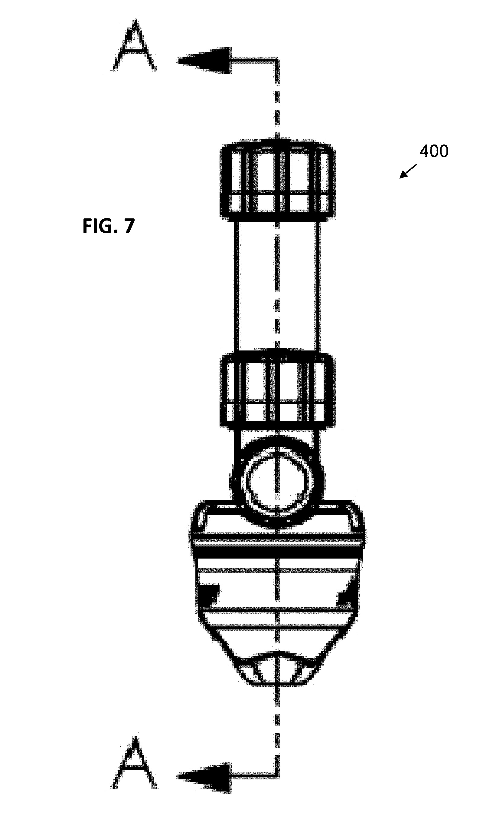
[0016] FIG. 7 is a somewhat schematic front view of the assembled HVAC fluid conditioning system of FIG. 5;
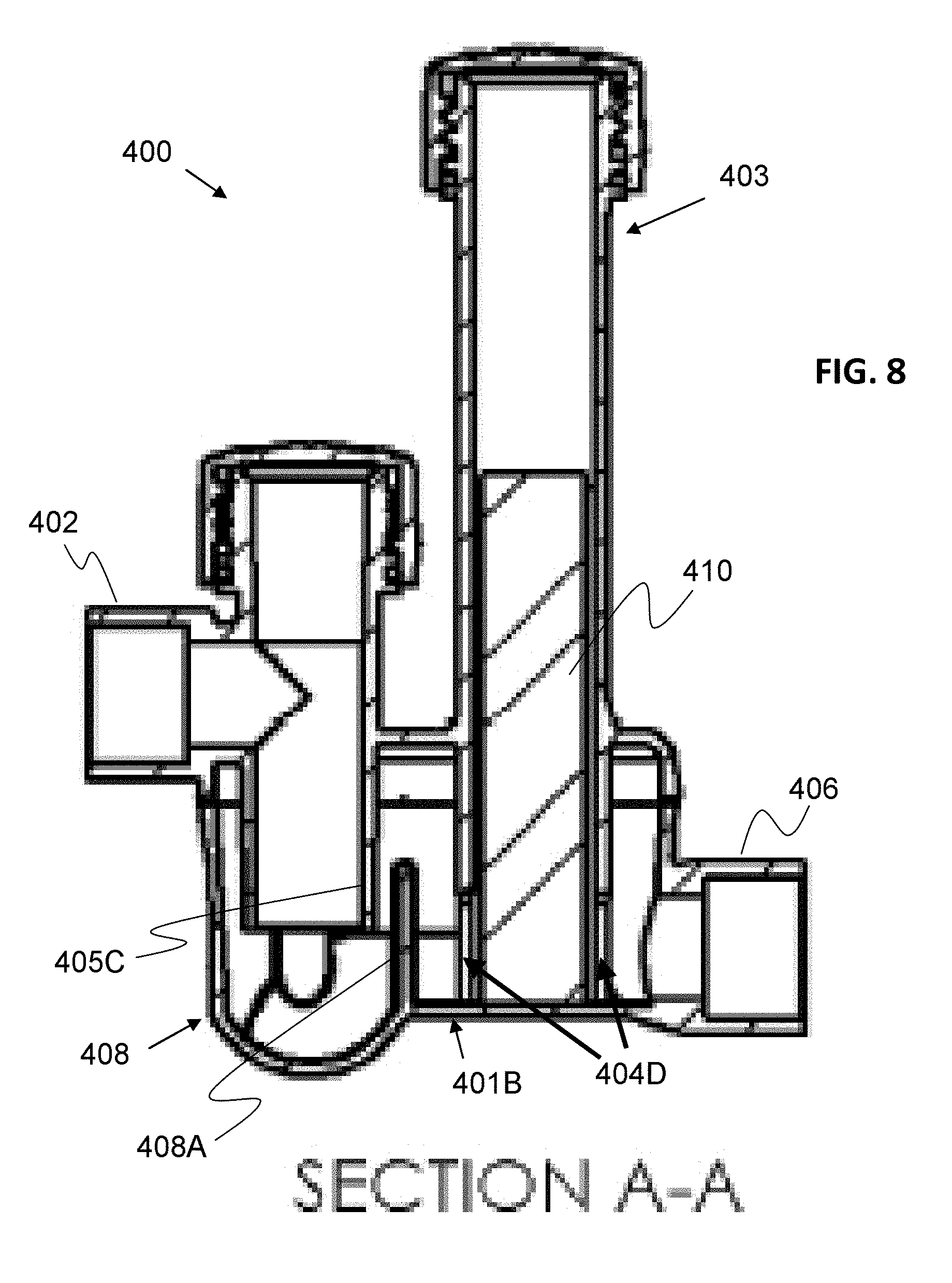
[0017] FIG. 8 is a somewhat schematic cross-sectional side view of the assembled HVAC fluid conditioning system of FIG. 5, taken along line A-A of FIG. 7; and
[0018] FIG. 8A is a reproduction of FIG. 8, but further includes arrows illustrating a flow of liquid through the HVAC fluid conditioning system.
DETAILED DESCRIPTION OF ILLUSTRATIVE EMBODIMENTS
[0019] Various features, benefits, and configurations incorporating the principles of the present inventive concepts in illustrative embodiments are shown in the accompanying drawings. Additional features, benefits, and configurations will be readily apparent to those of ordinary skill in the art based on this disclosure, and all such features, benefits, and configurations are considered within the scope of the present invention. Various embodiments will now be described in further detail in connection with the accompanying drawings.
[0020] FIG. 1 is a somewhat schematic cross-sectional side view of an HVAC fluid conditioning system 100 according to one embodiment of the present inventive concepts, including an inlet pipe connection 102, an outlet pipe connection 106, and a chlorine tablet dispenser 104 with a chlorine tablet (or rod) receptacle 105 housing chlorine tablets 110 (or a chlorine rod) therein. The chlorine dispenser 104 is preferably arranged between the inlet and outlet pipe connections 102, 106, respectively. FIG. 2 is a somewhat schematic perspective view of the chlorine tablet or rod container or receptacle 105 of the chlorine tablet or rod dispenser 104 of FIG. 1. And FIG. 3 is a somewhat schematic side view of the HVAC fluid conditioning system 100 of FIG. 1, showing the conditioning system 100 in transparent view and the chlorine tablet container 105 in side view. Arrows 112, 112A are further provided to illustrate the flow of liquid through the HVAC fluid conditioning system 100.
[0021] Referring to FIGS. 1 through 3, according to an embodiment of the present inventive concepts, a fluid conditioning unit 100 is installed in an HVAC unit (not shown) to dispense an appropriate amount of chlorine or other conditioning chemical into the fluid stream (represented by arrows 112) to condition the fluid 112 to kill and prevent growth of harmful pollutants.
[0022] More particularly, a fluid conditioning system 100 such as a chlorine or other chemical dispenser may be installed in an HVAC condensation line 120. The fluid conditioning system 100 may, for instance dispense a chlorine tablet 110 or other chemical tablet or rod into contact with the AC condensation water (or other conditioning fluid) 112 to eliminate algae and/or other harmful pollutants. By eliminating growth of harmful contaminants, the invention can provide a robust, reliable, and cost-effective solution for preventing clogged pipes and water back-ups due to contaminant growth in the HVAC system (not shown).
[0023] According to one embodiment, an HVAC fluid conditioning system 100 can be a chemical dispenser installed in the AC condensation line 120 of an HVAC system (not shown). Tablets 110 may be inserted into a container/receptacle 105 of the dispenser 100 and can feed into the condensation line 120. Condensation water 112 running through the condensation line 120 can pass by the tablet 110 (through holes or other openings 105A arranged in the container 105) and be conditioned with chlorine to kill and prevent the growth of algae and/or other harmful contaminants. The conditioned condensation water 112A is delivered back to the condensation line 120.
[0024] It should be noted that this system could be used in conjunction with a P or S trap plumbing system, for example, to keep chlorine fumes from entering into the structure being air conditioned. The trap system can, for instance, be installed upstream of the dispenser or be included as part of the dispenser to provide water to trap the chlorine fumes rather than permit them to enter the ambient air. Such a system will preferably prevent the HVAC system from sucking up the chlorine gas and spreading it to the structure being conditioned.
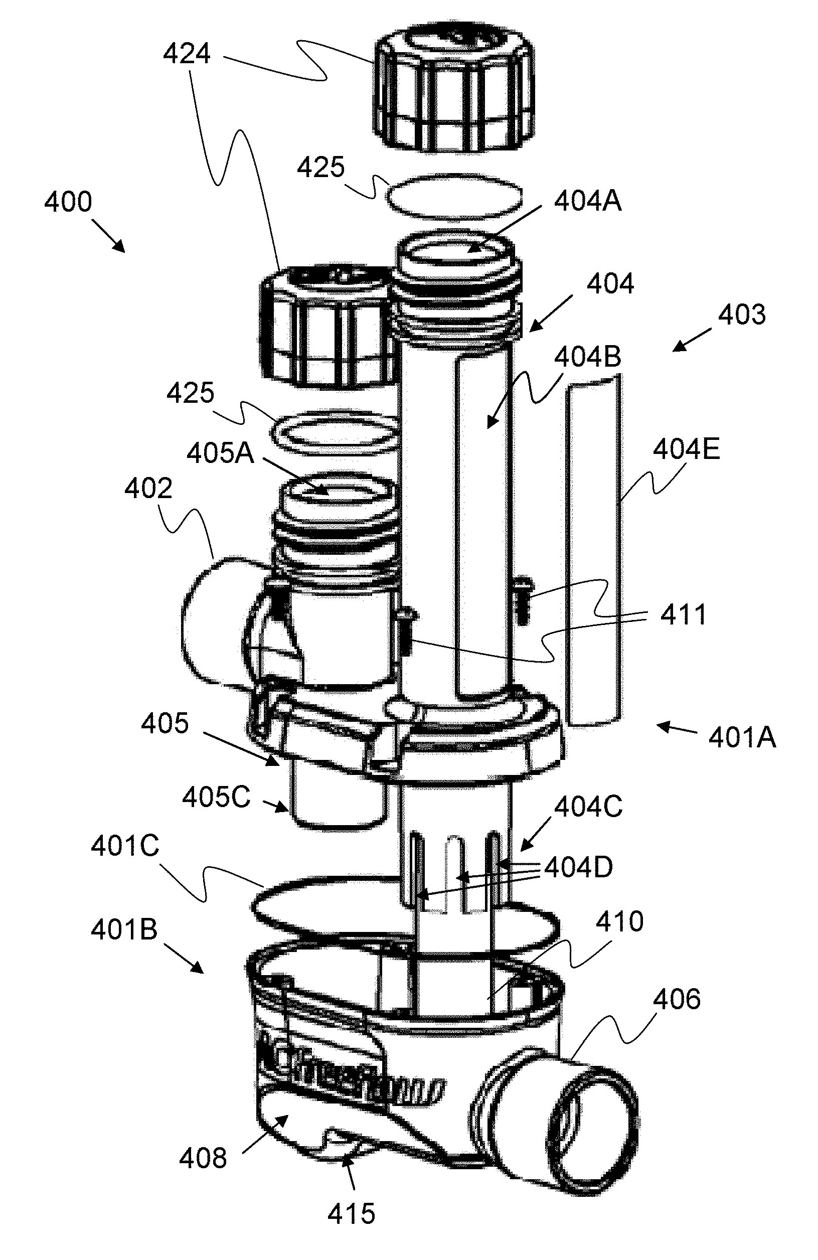
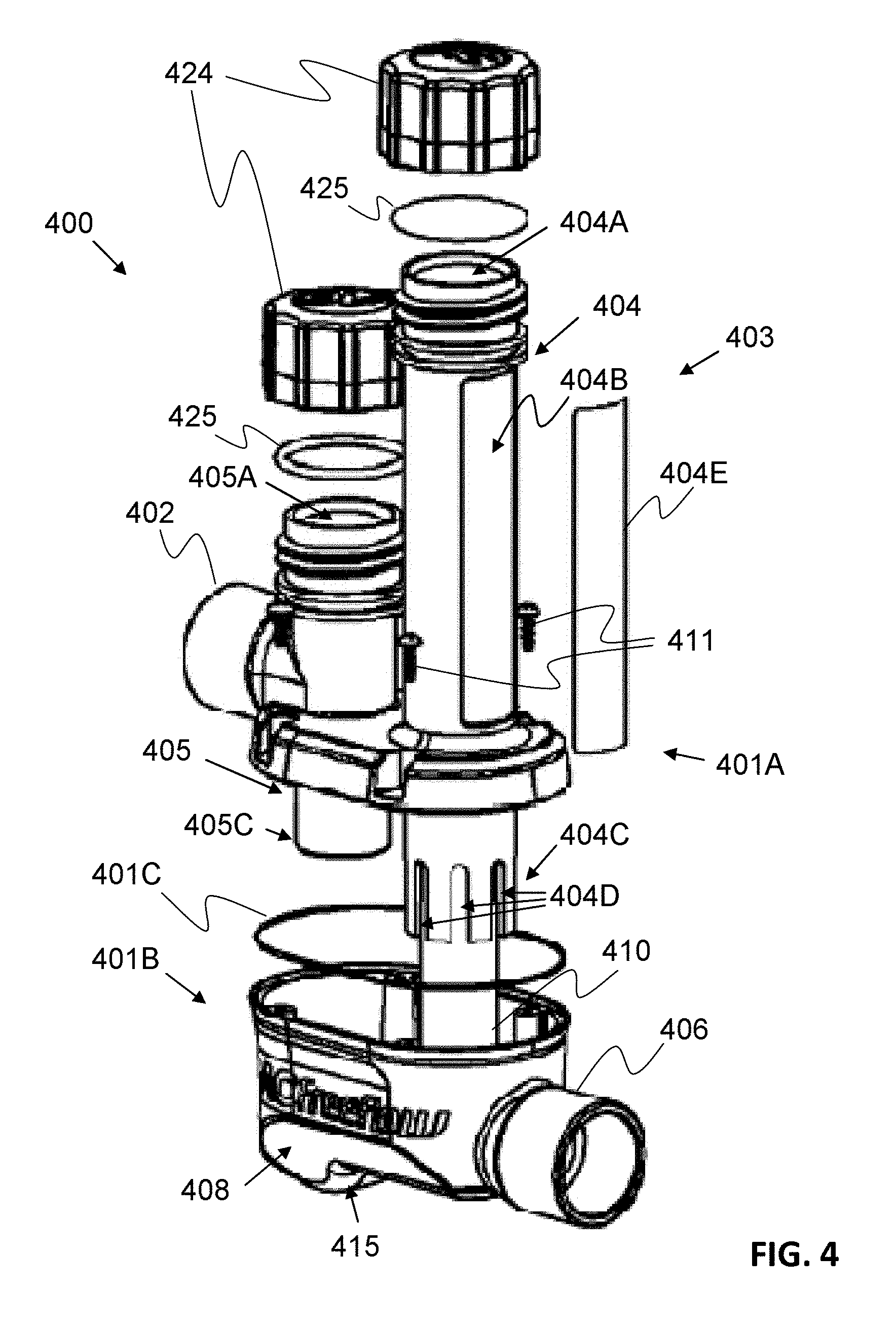
[0025] Of course, alternative embodiments are also possible. FIG. 4 is a somewhat schematic exploded perspective view of an HVAC fluid conditioning system 400 according to another embodiment of the present inventive concepts. FIG. 5 is a somewhat schematic perspective view of the assembled HVAC fluid conditioning system 400 of FIG. 4. FIG. 6 is a somewhat schematic side view of the assembled HVAC fluid conditioning system 400 of FIG. 5. FIG. 7 is a somewhat schematic front view of the assembled HVAC fluid conditioning system 400 of FIG. 5. FIG. 8 is a somewhat schematic cross-sectional side view of the assembled HVAC fluid conditioning system 400 of FIG. 5, taken along line A-A of FIG. 7. And FIG. 8A is a reproduction of FIG. 8, further including arrows 412, 412A to illustrate a flow of liquid through the HVAC fluid conditioning system 400.
[0026] Referring to FIGS. 4-8A, an HVAC fluid conditioning system 400 includes an inlet pipe connector 402, an outlet pipe connector 406, and a chlorine tablet or rod dispensing unit 403. In addition, however, the HVAC conditioning system 400 also preferably provides an S or P-type trap system 408 for trapping potentially hazardous fumes within the dispenser unit 400.
[0027] The HVAC fluid conditioning system 400 can include a housing 401 formed by connecting two sections (i.e., a top section 401A and a bottom section 401B) together, using screws 411 or some other connection mechanism. A seal 401C can be included between the top and bottom sections 401A, 401B, respectively, to prevent fluid leaks. The top section 401A can, for example, provide the chlorine tablet or rod dispenser unit 403, and the bottom section 401B can provide the S or P-type trap system 408.
[0028] The chlorine tablet or rod dispenser unit 403 can include a pipe or tube 404 with an opening 404B to receive chlorine tablets or a rod 410 therein. A door or cover 404E can be provided to cover the opening 404B after the chlorine tablets or rod 410 has been inserted. The bottom end 404C of the tube 404 can include slots, holes, or other openings 404D to permit the flow of fluid 412 therethrough.
[0029] In operation, chlorine tablets or a rod 410 inserted into the opening 404B of the chlorine tablet dispenser unit 403 may drop to the bottom 404C of the tube 404. Water or other HVAC liquid 412 enters the conditioning system through the inlet connector 402. The HVAC liquid 412 passes through the trap 408 and then through the openings 404D in the bottom 404C of the tube 404 and contacts the bottom-most tablet or rod 410 in the dispenser unit 403. As the HVAC liquid passes by the rod 410 (or tablets), it dissolves the rod 410 and thereby treats the HVAC liquid 412 with chlorine. The treated HVAC fluid 412A is then delivered back to the HVAC system through the outlet pipe connector 406.
[0030] Another pipe or tube 405 can be arranged near the inlet pipe connection 402 and over the S or P-type trap 408, with a bottom wall 405C thereof forming a part of the trap system. The bottom housing section 401B can provide a rounded portion 415 configured to direct liquid flow 412 around the wall 405C and into the dispenser unit 403. The bottom housing section 401B can also comprise a wall 408A that extends away from the housing bottom 401B to form an additional part of the trap system 408. The S or P-type trap system 408 preferably traps liquid in the bottom housing section 401B to form a liquid seal that keeps unwanted gases from escaping back through the inlet pipe connector 402 and into the HVAC system (not shown).
[0031] Depending on where the conditioning system 400 is installed, it could be pressurized from a pump or have water back up, and it is therefore important to have a watertight system that prevents leakage. Threaded caps 424 and seals 425 can therefore be included on the two tubes 404 and 405 to cover and seal openings 404A, 405A in the tops of the tubes to help provide a watertight system. The removable caps 424 further provide access to the tubes 404 and 405 for maintenance and cleaning and allow de-pressurization of the system 400. The threaded cap 424 over tube 405, for example, can be removed to permit access to, and cleaning of, the P trap 408 (in this embodiment). Additional chemicals could also be added through the top opening 405A in tube 405 to clean the trap 408 if there is ever a buildup of algae or other contaminants.
[0032] As explained above, an HVAC fluid conditioning system can prevent harmful pollutants from clogging or otherwise impairing a fluid flow through an HVAC system. A trap system can further ensure that harmful gases do not escape the HVAC fluid conditioning system and enter the structure being air conditioned. Having described and illustrated principles of the present invention in various preferred embodiments thereof, it should be apparent that the invention can be modified in arrangement and detail without departing from such principles.
* * * * *
D00000
D00001
D00002
D00003
D00004
D00005
D00006
D00007
D00008
D00009
XML
uspto.report is an independent third-party trademark research tool that is not affiliated, endorsed, or sponsored by the United States Patent and Trademark Office (USPTO) or any other governmental organization. The information provided by uspto.report is based on publicly available data at the time of writing and is intended for informational purposes only.
While we strive to provide accurate and up-to-date information, we do not guarantee the accuracy, completeness, reliability, or suitability of the information displayed on this site. The use of this site is at your own risk. Any reliance you place on such information is therefore strictly at your own risk.
All official trademark data, including owner information, should be verified by visiting the official USPTO website at www.uspto.gov. This site is not intended to replace professional legal advice and should not be used as a substitute for consulting with a legal professional who is knowledgeable about trademark law.