Sheet Stacker, Sheet Tray, Image Forming Apparatus, And Composite Image Forming Apparatus
Nishioka; Kunihiko ; et al.
U.S. patent application number 16/111943 was filed with the patent office on 2019-03-07 for sheet stacker, sheet tray, image forming apparatus, and composite image forming apparatus. This patent application is currently assigned to Ricoh Company, Ltd.. The applicant listed for this patent is Kunihiko Nishioka, Mizuna Tanaka. Invention is credited to Kunihiko Nishioka, Mizuna Tanaka.
| Application Number | 20190071268 16/111943 |
| Document ID | / |
| Family ID | 65517792 |
| Filed Date | 2019-03-07 |


View All Diagrams
| United States Patent Application | 20190071268 |
| Kind Code | A1 |
| Nishioka; Kunihiko ; et al. | March 7, 2019 |
SHEET STACKER, SHEET TRAY, IMAGE FORMING APPARATUS, AND COMPOSITE IMAGE FORMING APPARATUS
Abstract
A sheet stacker includes a body to stack a sheet, a fence to regulate a position of the sheet, and a support. The body includes a groove extending in a predetermined direction. The support includes a support portion to support the fence and a projection extending in the predetermined direction. The groove engages with the projection in a sheet stacking direction to secure the support. The fence is supported to be rotatable about the support portion of the support.
| Inventors: | Nishioka; Kunihiko; (Kanagawa, JP) ; Tanaka; Mizuna; (Tokyo, JP) | ||||||||||
| Applicant: |
|
||||||||||
|---|---|---|---|---|---|---|---|---|---|---|---|
| Assignee: | Ricoh Company, Ltd. Tokyo JP |
||||||||||
| Family ID: | 65517792 | ||||||||||
| Appl. No.: | 16/111943 | ||||||||||
| Filed: | August 24, 2018 |
| Current U.S. Class: | 1/1 |
| Current CPC Class: | B65H 2402/5151 20130101; B65H 2511/11 20130101; B65H 2511/20 20130101; B65H 1/266 20130101; B65H 2220/01 20130101; B65H 2220/04 20130101; B65H 2402/31 20130101; B65H 2511/11 20130101; B65H 1/04 20130101; B65H 2511/20 20130101 |
| International Class: | B65H 1/26 20060101 B65H001/26 |
Foreign Application Data
| Date | Code | Application Number |
|---|---|---|
| Sep 7, 2017 | JP | 2017-172185 |
Claims
1. A sheet stacker comprising: a body to stack a sheet, the body including a groove extending in a predetermined direction; a fence to regulate a position of the sheet; and a support including: a support portion to support the fence; and a projection extending in the predetermined direction, the groove to engage with the projection in a sheet stacking direction to secure the support, the fence supported to be rotatable about the support portion of the support.
2. The sheet stacker according to claim 1, wherein a plurality of projections including the projection is provided in a direction perpendicular to the predetermined direction, a plurality of grooves including the groove is provided in the direction perpendicular to the predetermined direction, and the plurality of projections engages with the plurality of grooves in the sheet stacking direction.
3. The sheet stacker according to claim 1, wherein a rotation fulcrum of the fence is located within a range corresponding to a width of the projection in the predetermined direction.
4. The sheet stacker according to claim 1, wherein a rotation fulcrum of the fence is located on an outer surface of the support portion.
5. The sheet stacker according to claim 1, wherein the support portion has a semi-cylindrical shape.
6. The sheet stacker according to claim 1, wherein the support portion has a triangular prism shape.
7. The sheet stacker according to claim 1, wherein the support portion has a hemisphere shape.
8. The sheet stacker according to claim 1, wherein the fence slidably rotates about the support portion.
9. The sheet stacker according to claim 8, wherein the support portion has a cylindrical shape.
10. The sheet stacker according to claim 8, wherein a portion of the fence supported by the support portion has a cross-sectional arced concave shape.
11. The sheet stacker according to claim 8, wherein the support portion has a cylindrical shape, and a portion of the fence supported by the support portion has a cross-sectional arced concave shape.
12. The sheet stacker according to claim 1, wherein the support portion is made of an elastic body.
13. A sheet tray comprising the sheet stacker according to claim 1, wherein the sheet tray is drawably inserted in an apparatus body of an image forming apparatus.
14. An image forming apparatus comprising the sheet stacker according to claim 1.
15. A composite image forming apparatus comprising the sheet stacker according to claim 1.
Description
CROSS-REFERENCE TO RELATED APPLICATION
[0001] This patent application is based on and claims priority pursuant to 35 U.S.C. .sctn. 119(a) to Japanese Patent Application No. 2017-172185, filed on Sep. 7, 2017, in the Japan Patent Office, the entire disclosure of which is hereby incorporated by reference herein.
BACKGROUND
Technical Field
[0002] This disclosure generally relates to a sheet stacker, a sheet tray, an image forming apparatus, and a composite image forming apparatus that includes the sheet stacker.
Description of the Related Art
[0003] For an image forming apparatus, a sheet tray is generally provided with a fence, such as an end fence or a side fence. The fence is movable to regulate a position of a recording sheet stacked on the sheet tray. A projection of the fence engages with a groove provided on a body of the sheet tray to secure the position of the fence.
SUMMARY
[0004] According to an embodiment of the present disclosure, an improved sheet stacker includes a body to stack a sheet, a fence to regulate a position of the sheet, and a support. The body includes a groove extending in a predetermined direction. The support includes a support portion to support the fence and a projection extending in the predetermined direction. The groove engages with the projection in a sheet stacking direction to secure the support. The fence is supported to be rotatable about the support portion of the support.
BRIEF DESCRIPTION OF THE SEVERAL VIEWS OF THE DRAWINGS
[0005] A more complete appreciation of the disclosure and many of the attendant advantages thereof will be readily obtained as the same becomes better understood by reference to the following detailed description when considered in connection with the accompanying drawings, wherein:
[0006] FIG. 1 is a perspective view of a laser printer as an example of an image forming apparatus according to an embodiment of the present disclosure;
[0007] FIG. 2 is a cross-sectional view of the laser printer as the example of the image forming apparatus according to an embodiment of the present disclosure;
[0008] FIG. 3 is a perspective view of a sheet tray according to an embodiment of the present disclosure;
[0009] FIG. 4 is a perspective view of a portion of the sheet tray on an end fence side according to an embodiment of the present disclosure;
[0010] FIG. 5A is a perspective view of a support according to a first embodiment of the present disclosure;
[0011] FIG. 5B is a cross-sectional perspective view of the sheet tray along V-V line illustrated in FIG. 4;
[0012] FIG. 5C is an enlarged view of a portion of the sheet tray in a dashed circle D1 illustrated in FIG. 5B;
[0013] FIG. 6A is a cross-sectional view of the sheet tray along VI-VI line illustrated in FIG. 5B;
[0014] FIG. 6B is an enlarged view of a portion of the sheet tray in a rectangle D2 illustrated in FIG. 6A;
[0015] FIG. 7 is a schematic view illustrating a range in which a rotation fulcrum of an end fence exists;
[0016] FIG. 8 is a schematic view illustrating a force acting on the end fence according to the first embodiment of the present disclosure;
[0017] FIG. 9A is a perspective view of a support according to a second embodiment of the present disclosure;
[0018] FIG. 9B is a partial cross-sectional view of a portion of a sheet tray on the end fence side according to the second embodiment of the present disclosure;
[0019] FIG. 10A is a perspective view of a support according to a third embodiment of the present disclosure;
[0020] FIG. 10B is a partial cross-sectional view of a portion of a sheet tray on the end fence side according to the third embodiment of the present disclosure;
[0021] FIG. 11A is a perspective view of a support according to a fourth embodiment of the present disclosure;
[0022] FIG. 11B is a partial cross-sectional view of a portion of a sheet tray on the end fence side according to the fourth embodiment of the present disclosure;
[0023] FIG. 11C is an enlarged view of a portion of the sheet tray in a rectangle D3 illustrated in FIG. 11B;
[0024] FIG. 12A is a partial cross-sectional view of a portion of a sheet tray on an end fence side according to a fifth embodiment of the present disclosure;
[0025] FIG. 12B is a perspective view of a mount of an end fence from which a support is removed as viewed in a direction indicated by arrow D;
[0026] FIG. 12C is an enlarged view of a portion of the sheet tray in a rectangle D4 illustrated in FIG. 12A;
[0027] FIG. 13 is a schematic view illustrating a configuration of a mount of an end fence and the support according to a sixth embodiment of the present disclosure;
[0028] FIG. 14A is a perspective view of a support according to a comparative sheet tray;
[0029] FIG. 14B is a partial cross-sectional perspective view of a portion of a sheet tray on the end fence side according to the comparative sheet tray;
[0030] FIG. 14C is a partial cross-sectional view of the portion of the sheet tray on the end fence side according to the comparative sheet tray of the present disclosure;
[0031] FIG. 14D is an enlarged schematic view of a portion of the sheet tray in a rectangle D5 illustrated in FIG. 14C;
[0032] FIG. 15A is a partial cross-sectional view of a portion of the sheet tray on the end fence side according to the comparative sheet tray;
[0033] FIG. 15B is an enlarged view of a portion of the sheet tray in a rectangle D6 illustrated in FIG. 15A;
[0034] FIG. 15C is a schematic view illustrating a force acting on the end fence and the support according to the comparative sheet tray; and
[0035] FIG. 15D is a schematic view illustrating a state in which a projection ride over a groove according to the comparative sheet tray.
[0036] The accompanying drawings are intended to depict embodiments of the present disclosure and should not be interpreted to limit the scope thereof. The accompanying drawings are not to be considered as drawn to scale unless explicitly noted. In addition, identical or similar reference numerals designate identical or similar components throughout the several views.
DETAILED DESCRIPTION
[0037] In describing embodiments illustrated in the drawings, specific terminology is employed for the sake of clarity. However, the disclosure of this patent specification is not intended to be limited to the specific terminology so selected, and it is to be understood that each specific element includes all technical equivalents that have the same function, operate in a similar manner, and achieve a similar result.
[0038] As used herein, the singular forms "a", "an", and "the" are intended to include the plural forms as well, unless the context clearly indicates otherwise.
[0039] It is to be noted that the suffixes Y, M, C, and K attached to each reference numeral indicate only that components indicated thereby are used for forming yellow, magenta, cyan, and black images, respectively, and hereinafter may be omitted when color discrimination is not necessary.
[0040] Descriptions are given of an embodiment of the present disclosure with reference to the drawings.
First Embodiment
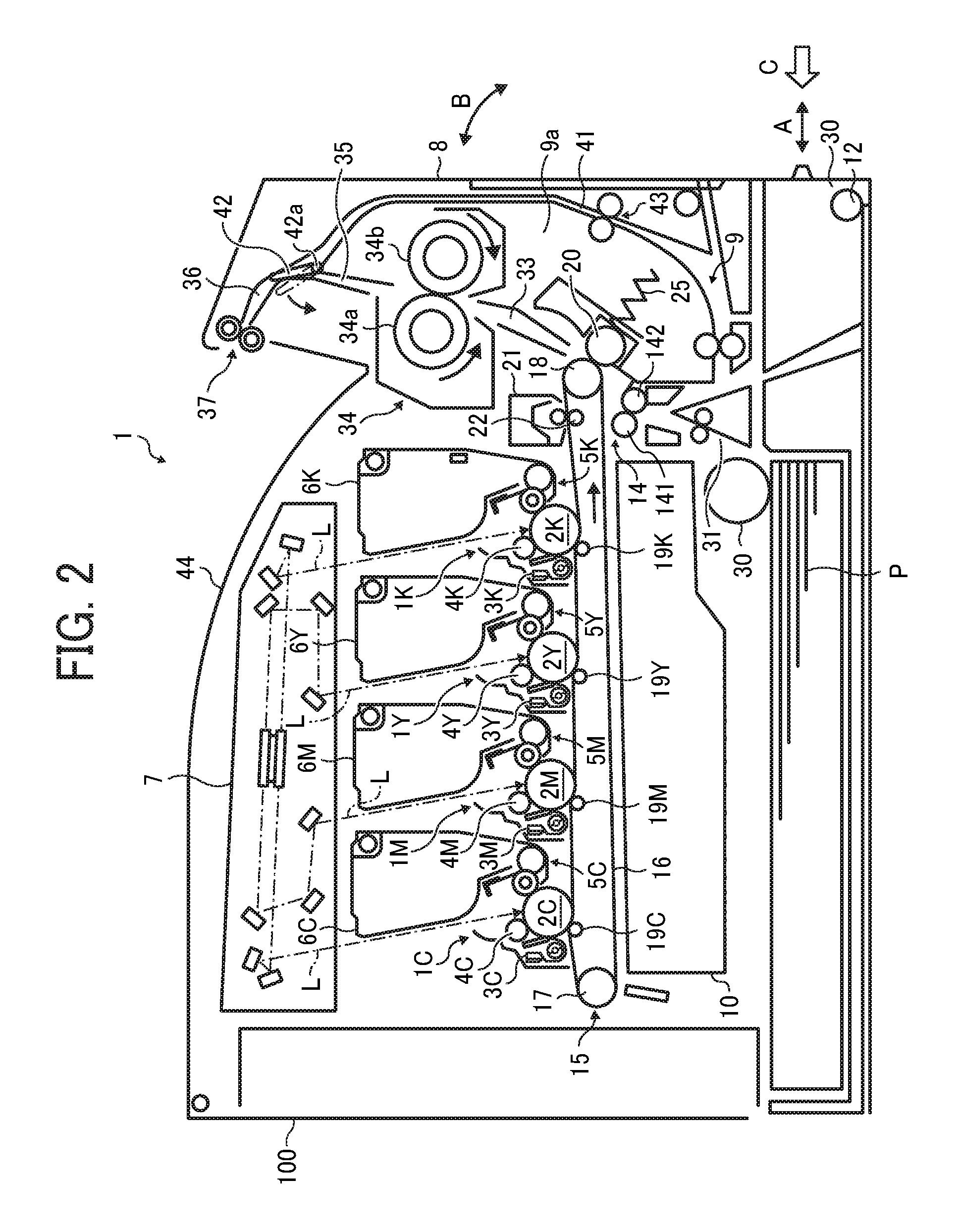
[0041] FIG. 1 is a perspective view of a laser printer 1 as an example of an image forming apparatus according to an embodiment of the present disclosure. FIG. 2 is a cross-sectional view of the laser printer 1.
[0042] Note that the term "image forming apparatus" indicates an apparatus in which an image is formed on a sheet that functions as a recording medium by attaching developer or ink thereto. Further, it is to be noted that the term "image formation" indicates an action for providing (i.e., printing) not only an image having meanings such as texts and figures on a recording medium but also an image having no meaning such as patterns on a recording medium. Note that the term "sheet" includes not only paper but also any material called recording medium or document, such as an overhead projector (OHP) sheet, a textile, and the like, to which developer or ink adheres. The term "sheet" is not limited to a plain paper but also is applicable to a thick paper, a post card, an envelope, a thin paper, a coated paper, an art paper, and a tracing paper. In the following embodiments, the "sheet" indicates a paper, and size (dimension), material, shape, and relative positions used to describe each of the components and units are examples, and the scope of the present disclosure is not limited thereto unless otherwise specified.
[0043] As illustrated in FIG. 1, a sheet tray 30 as an example of a sheet stacker accommodating multiple sheets therein is disposed at a lower part of an apparatus body 100 of the laser printer 1. The sheet tray 30 is drawably inserted into the apparatus body 100 in a direction indicated by arrow A in FIG. 1. A front cover 8 is disposed above the sheet tray 30 to inspect an interior of the apparatus body 100. The front cover 8 is openable and closable relative to the apparatus body 100 in a front and back direction indicated by arrow B in FIG. 1. Specifically, as illustrated in FIG. 2, the front cover 8 is hinged on a rotary shaft 12 that is disposed at the lower part of the apparatus body 100 and rotatable about the rotary shaft 12. A sheet ejection tray 44 is disposed at a top of the apparatus body 100.
[0044] The front cover 8 includes a duplex printing unit 9 therein. The duplex printing unit 9 includes a sheet conveyance housing 9a. A reversal conveyance path 41 is arranged at a rear side of the sheet conveyance housing 9a. The sheet conveyance housing 9a includes an inner side that defines part of sheet conveyance paths of the apparatus body 100. The inner side of the sheet conveyance housing 9a includes the secondary transfer roller 20 as a transferor and a timing drive roller 142 that is one roller of the timing roller pair 14. The timing roller pair 14 includes a timing driven roller 141 disposed on the apparatus body 100 side together with the timing drive roller 142.
[0045] A principal part of the laser printer 1 is described below with reference to FIG. 2.
[0046] The laser printer 1 includes four process units 1K, 1Y, 1M, and 1C to form an image of black (K), yellow (Y), magenta (M), and cyan (C) with developers corresponding to color separation components of a color image, respectively. The process units 1K, 1Y, 1M, and 1C respectively include toner bottles 6K, 6Y, 6M, and 6C containing unused toners of different colors. The process units 1K, 1Y, 1M, and 1C have a similar structure except the color of toner.
[0047] For example, the process unit 1K includes are a photoconductor (a photoconductor drum) 2K, a drum cleaner 3K, a discharger, a charger 4K, and a developing device 5K. The process unit 1K is removably installed in the apparatus body 100 of the laser printer 1 so that consumables are replaceable at a time.
[0048] An exposure device 7 is disposed above the process units 1K, 1Y, 1M, and 1C. The exposure device 7 emits laser lights L from laser diodes disposed therein based on image data.
[0049] A transfer device 15 is disposed below the process units 1K, 1Y, 1C, and 1M. The transfer device 15 includes four primary transfer rollers 19K, 19Y, 19M, and 19C disposed opposite the respective photoconductors 2K, 2Y, 2M, and 2C; an intermediate transfer belt 16 looped around the primary transfer rollers 19K, 19Y, 19M, and 19C, a drive roller 18, and a driven roller 17; the secondary transfer roller 20 disposed opposite the drive roller 18; a belt cleaner 21; and a cleaning backup roller 22. The drive roller 18 cyclically drives the intermediate transfer belt 16. The photoconductors 2K, 2Y, 2M, and 2C are defined as first image bearers, and the intermediate transfer belt 16 is a second image bearer that carries a composite image made from images on the respective photoconductors 2K, 2Y, 2M, and 2C.
[0050] The sheet tray 30 to accommodate multiple sheets P therein and sheet feed roller 32 to feed the sheet P from the sheet tray 30 to a sheet feeding path 31 are disposed at the lower part of the apparatus body 100 of the laser printer 1. The timing roller pair 14 for temporarily stopping the sheet is disposed near the end of the sheet feeding path 31.
[0051] The timing roller pair 14 is disposed near the intermediate transfer belt 16 at the immediately upstream side in the conveyance direction of the sheet P. The timing roller pair 14 temporarily stops the sheet P, slacks the sheet P once, and feeds the sheet P to a secondary transfer nip at a predetermined timing immediately before the toner image on the intermediate transfer belt 16 is transferred onto the sheet P.
[0052] The secondary transfer roller 20 is generally biased by a compression spring 25 toward the intermediate transfer belt 16. However, the laser printer 1 of a full front operation type includes the duplex printing unit 9 that is generally disposed on a near side (a front side) of the intermediate transfer belt 16. Therefore, the size of parts disposed around the compression spring 25 is hardly reduced. As illustrated in FIG. 2, the secondary transfer nip is obliquely arranged, that is, the secondary transfer roller 20 contacts the drive roller 18 from an oblique direction (from a lower right side in FIG. 2) with respect to the horizontal direction. By so doing, the dead space or the unused space of the duplex printing unit 9 can be effectively used, and as a result, the laser printer 1 can be reduced in size in the front and rear direction of the laser printer 1.
[0053] A post-transfer conveyance path 33 is disposed above the secondary transfer nip formed between the secondary transfer roller 20 and the drive roller 18. A fixing device 34 is disposed near the end of the post-transfer conveyance path 33. The fixing device 34 includes a fixing roller 34a in which a heat source such as a halogen lamp is provided and a pressure roller 34b to rotate in contact with the fixing roller 34a at a predetermined pressure.
[0054] A post-fixing conveyance path 35 is disposed above the fixing device 34. The post-fixing conveyance path 35 branches at a downstream end thereof into two paths, which are a sheet ejection path 36 and the reversal conveyance path 41. A switching member 42 that is pivotally driven about a pivotal shaft 42a is disposed on the side of the post-fixing conveyance path 35. A sheet ejection roller pair 37 to eject a sheet outside the apparatus body 100 is disposed at the end of the sheet ejection path 36. The reversal conveyance path 41 merges with the sheet feeding path 31 at the end of the reversal conveyance path 41, and a reversal conveyance roller pair 43 is disposed in the middle of the reversal conveyance path 41. A sheet ejection tray 44 including an upper cover recessed inward is disposed at the top of the laser printer 1.
[0055] A waste toner container 10 to contain waste toner is disposed between the transfer device 15 and the sheet tray 30. The waste toner container 10 is removably installed in the apparatus body 100.
[0056] In the laser printer 1 according to the present embodiment, the sheet feed roller 32 is preferably separated from the secondary transfer roller 20 by a certain distance or gap due to conveyance of the sheet. The waste toner container 10 is disposed in a dead space caused by the above-described distance to keep the entire laser printer 1 compact.
[0057] Note that the laser printer 1 is described as an exemplary embodiment of the image forming apparatus according to the present disclosure, but the present disclosure is applicable to any of a copier, a facsimile machine, a printer including the laser printer, a printing machine, and an ink jet recording device, or a composite image forming apparatus, such as a multifunction peripheral (MFP), including not limited thereto at least two functions of the copier, facsimile machine, printer, printing machine, and ink jet recording device.
[0058] Subsequently, a description is provided of basic operation of the laser printer 1.
[0059] In FIG. 2, as the sheet feed roller 32 starts to rotate in response to a sheet feed signal issued by a controller of the laser printer 1, an uppermost sheet P placed on top of a bundle of sheets P loaded on the sheet tray 30 is separated from the other sheets of the bundle of sheets P and is forwarded into the sheet feeding path 31. When the leading end of the sheet P reaches a nip of the timing roller pair 14, the sheet P stands by with slack formed thereat in order to take timing (synchronize) with the toner image to be formed on the intermediate transfer belt 16 and to correct skew at leading end of the sheet P.
[0060] A description is given of image forming operations, as an example, regarding the process unit 1K for black toner. First, the charger 4K uniformly charges a surface of the photoconductor 2K to a high electric potential. Based on image data, a laser light L is emitted from the exposure device 7 to the charged surface of the photoconductor 2K, so that the electric potential at the emitted portions on the surface of the photoconductor 2K decreases to form an electrostatic latent image. An unused black toner is supplied from the toner bottle 6K to the developing device 5K.
[0061] The developing device 5K supplies toner onto the electrostatic latent image on the surface of the photoconductor 2K, thus developing (visualizing) the electrostatic latent image into a visible image as a toner image. The toner image is transferred from the photoconductor 2K onto the intermediate transfer belt 16 (i.e., a primary transfer process).
[0062] The drum cleaner 3K removes residual toner adhering to the photoconductor 2K after the primary transfer process. The removed residual toner is transported to a waste toner container housed inside the process unit 1K by a waste toner conveyor and is collected in the waste toner container. The discharger eliminates electric charges remaining on the photoconductor 2K after the cleaning process.
[0063] The above-described detailed operations are also performed in each of the process units 1Y, 1M, and 1C. For example, respective toner images are formed on the respective surfaces of the photoconductors 2Y, 2M, and 2C and are then sequentially transferred and deposited one on another onto the surface of the intermediate transfer belt 16 to form a full-color toner image.
[0064] As the respective color toner images have been sequentially transferred in layers onto the surface of the intermediate transfer belt 16 to form the superimposed full-color toner image, the timing roller pair 14 and the sheet feed roller 32 start rotating, so that the sheet P is conveyed to the secondary transfer roller 20 at the same timing as (in synchronization with) movement of the full-color toner image transferred and overlaid onto the surface of the intermediate transfer belt 16. The full-color toner image formed on the intermediate transfer belt 16 is transferred onto the sheet P at the secondary transfer nip at which the secondary transfer roller 20 faces the intermediate transfer belt 16 (i.e., a secondary transfer process).
[0065] The sheet P bearing the toner image is transported through the post-transfer conveyance path 33 to the fixing device 34. As the sheet P is sent into the fixing device 34 and sandwiched between the fixing roller 34a and the pressure roller 34b, the unfixed toner image on the sheet P is fixed to the sheet P under heat and pressure. The fixing device 34 sends out the sheet P carrying the fixed toner image to the post-fixing conveyance path 35.
[0066] At the timing at which the sheet P is ejected from the fixing device 34, the switching member 42 is located at the position illustrated by a solid line in FIG. 2, which allows the sheet P to pass around an open space at the end of the post-fixing conveyance path 35. After traveling from the fixing device 34, the sheet P passes through the post-fixing conveyance path 35 and the sheet ejection path 36. Then, the sheet P is held by and passes through the sheet ejection roller pair 37 to be discharged to the sheet ejection tray 44.
[0067] In the duplex printing, as a trailing end of the sheet P conveyed by the sheet ejection roller pair 37 passes through the post-fixing conveyance path 35, the switching member 42 rotates about the pivotal shaft 42a to a position indicated by a broken line in FIG. 2 to block the passage of the sheet P at and around the end of the post-fixing conveyance path 35. Substantially simultaneously, the sheet ejection roller pair 37 rotates in reverse to feed the sheet P in an opposite direction to the reversal conveyance path 41.
[0068] The sheet P conveyed in the reversal conveyance path 41 passes through the reversal conveyance roller pair 43 and reaches the timing roller pair 14. The timing roller pair 14 measures optimal timing to transfer the toner image formed on the surface of the intermediate transfer belt 16 onto an unprinted side, i.e., a reverse side of the sheet P in synchronization with movement of the toner image formed on the surface of the intermediate transfer belt 16. When the sheet P passes by the secondary transfer roller 20, the toner image is transferred onto the reverse side of the sheet P. In the fixing device 34, the sheet P is held between the fixing roller 34a and the pressure roller 34b to fix the unfixed toner image formed on the reverse side of the sheet P to the sheet P under heat and pressure. The sheet P with the fixed toner image on the reverse side thereof is conveyed through the post-fixing conveyance path 35, the sheet ejection path 36, and the sheet ejection roller pair 37 in this order and ejected to the sheet ejection tray 44.
[0069] After the toner image on the intermediate transfer belt 16 is transferred onto the sheet P, there is toner remaining on the intermediate transfer belt 16. The belt cleaner 21 removes toner remaining on the intermediate transfer belt 16 after the secondary transfer process. The toner removed from the intermediate transfer belt 16 is transported by a waste toner conveyor to an entrance of the waste toner container 10 and collected in the waste toner container 10.
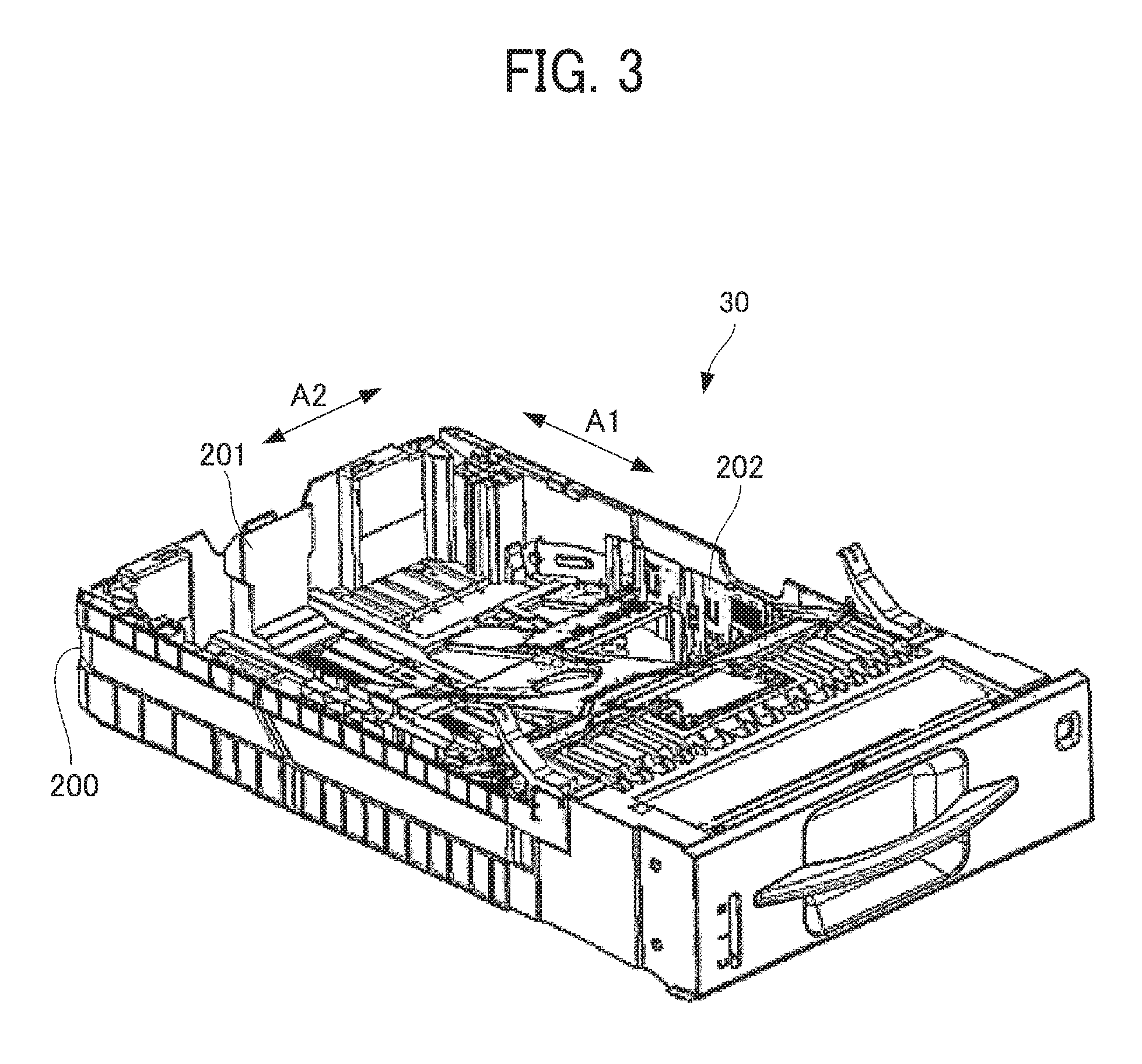
[0070] Next, descriptions are given below of the sheet tray 30 as an example of the sheet stacker according to the present embodiment with reference to FIGS. 3 through 6B.
[0071] FIG. 3 is a perspective view of the sheet tray 30, and FIG. 4 is a perspective view of a portion of the sheet tray 30 on an end fence 201 side. FIG. 5A is a perspective view of a support 206, FIG. 5B is a cross-sectional perspective view of the sheet tray 30 along a line V-V illustrated in FIG. 4, and FIG. 5C is an enlarged view of a portion in a dashed circle D1 illustrated in FIG. 5B. FIG. 6A is a cross-sectional view of the sheet tray 30 along a line VI-VI illustrated in FIG. 5B, and FIG. 6B is an enlarged view of a portion in a rectangle D2 illustrated in FIG. 6A.
[0072] As illustrated in FIGS. 3 to 5C, the sheet tray 30 includes a tray body 200 of the sheet tray 30 as an example of a body of the sheet stacker, an end fence 201 as an example of a fence, a support (a lock member) 206, and a groove (a ratchet) 205 provided on the tray body 200. The tray body 200 includes a bottom plate 203, and a sheet (e.g., a paper sheet) is stacked on the bottom plate 203.
[0073] As illustrated in FIG. 4, the bottom plate 203 of the tray body 200 includes a rail 204 having a plurality of groove (the ratchet) 205 parallel to each other. The rail 204 extends along a direction of movement of the end fence 201 indicated by arrow A1. The groove 205 extends in a width direction of the sheet indicated by arrow A2 in FIG. 4 and engages with a projection (a pawl) 209 of the support 206 in a direction indicated by arrow A3 in FIG. 5B to stack sheets (i.e., z-direction in FIG. 5B). Thus, the support 206 and the end fence 201 enclosing the support 206 are secured.
[0074] The respective elements are described in detail below.
[0075] The end fence 201 regulates a position of the trailing end of the sheet in a direction of conveyance of the sheet (i.e., x-direction in FIG. 5B). As illustrated in FIG. 5B, the end fence 201 is movable in a direction indicated by arrow A1 to change a position thereof according to the sizes of various sheets. As illustrated in FIG. 3, a pair of side fences 202 as the fence is provided to secure a position of the end of the stacked sheet in the width direction of the sheet indicated by arrow A2.
[0076] Specifically, as illustrated in FIG. 5B, the end fence 201 includes a fence body 201a of the end fence 201 extending in the direction (i.e., z-direction) to stack sheets, a base 201b, and a mount 201c in which the support 206 is enclosed. The base 201b extends substantially parallel to the bottom plate 203 of the sheet tray 30 and has a sloped step therein. The fence body 201a regulates the end position of the stacked sheet.
[0077] As illustrated in FIGS. 6A and 6B, the mount 201c of the end fence 201 is concave, in which the support 206 is enclosed. The support 206 enclosed in the mount 201c is not detached backward from the mount 201c by a projection 201e disposed at rear end portion of the mount 201c.
[0078] As illustrated in FIG. 5A, the support (the lock member) 206 includes a support portion (a contact portion) 208 to support the end fence 201 and the projection (the pawl) 209 extending in a predetermined direction.
[0079] Specifically, the support portion (the contact portion) 208 protrudes from a front face 207c of a support body 207 on the fence body 201a side and has a semi-cylindrical shape. The projection 209 is disposed at a lower end 207b of the support body 207 and extends in the width direction of the sheet indicated by arrow A2 in FIG. 5B.
[0080] The projection (the pawl) 209 of the support (the lock member) 206 and the groove (the ratchet) 205 of the rail 204 extend in the predetermined direction that is preferably perpendicular to the direction of movement of the support 206 and the end fence 201 (the direction of conveyance of the sheet or x-direction in FIG. 5B). That is, the predetermined direction is the width direction of the sheet indicated by arrow A2 illustrated in FIG. 5B. With such a configuration, the projection 209 of the support 206 can easily move from one position of the groove 205 of the rail 204 to another position of the groove 205 of the rail 204 while disengaging from the groove 205 of the rail 204.
[0081] In the present embodiment, the support portion 208 has, but not limited to, the semi-cylindrical shape, in which a substantially half of a cylinder protrudes. Alternatively, the support portion 208 may has a shape in which a part of a cylinder protrudes.
[0082] A plurality of projections 209 is provided in a direction perpendicular to the predetermined direction, and a plurality of grooves 205 of the rail 204 is provided in the direction perpendicular to the predetermined direction. The plurality of projections 209 engages with the respective plurality of grooves 205 of the rail 204 in the direction to stack sheets (i.e., z-direction in FIG. 5B). Hereinafter, the direction to stack sheets is referred to as a sheet stacking direction. With such a configuration, the support 206 can be reliably secured as compared with the case of one pair of the projection 209 and the groove 205.
[0083] Specifically, as illustrated in FIGS. 5B and 5C, the support 206 includes the plurality of projection 209 extending in the width direction of the sheet (the direction perpendicular to the paper on which FIG. 5C is drawn). In other words, the plurality of projections 209 is provided in the direction, indicated by arrow A1 in FIG. 5B, perpendicular to the width direction of the sheet. In the present embodiment, the number of projections 209 of the support 206 is six, but is not limited thereto. The plurality of grooves 205 of the rail 204 is provided in the direction, indicated by arrow A1 in FIG. 5B, perpendicular to the width direction of the sheet.
[0084] In the present embodiment, the plurality of projections 209 and the plurality of grooves 205 are provided. Alternatively, the number of projections 209 can be one, or the number of projections 209 and the number of grooves 205 can be one, respectively. Further, the cross-sectional shapes of the projection 209 and the groove 205 are not limited to triangle, but also can be rectangular or oval.
[0085] As illustrated in FIGS. 6A and 6B, the support 206 is enclosed in the mount 201c of the end fence 201, and the end fence 201 is supported to be rotatable about the support portion 208 of the support 206.
[0086] Specifically, as illustrated in FIG. 6B, the support portion (the contact portion) 208 having the semi-cylindrical shape contacts an inner surface of the mount 201c at one contact point X2 of an arced surface of the support portion 208 as viewed in the cross-section, thereby supporting the end fence 201. Further, both side faces 207d of the support body 207 of the support 206, which face an inner face 201d of the mount 201c, are curved as viewed in the cross-section in FIG. 6B. Therefore, the end fence 201 is rotatable around the contact point X2 as a rotation fulcrum S as viewed in the cross-section in FIG. 6B. That is, the support 206 has the rotation fulcrum S of the end fence 201 on the surface of the support portion 208.
[0087] A rotation range (a movable range) of the end fence 201 relative to the support portion 208 is set to a range in which the end fence 201 can be rotated due to impact on the end fence 201. In the present embodiment, the rotation range is approximately 5 degrees (refer to an angle .theta. in FIG. 8).
[0088] FIG. 7 is a schematic view illustrating a range in which the rotation fulcrum S of the end fence 201 exists. As illustrated in FIG. 7, the support portion 208 has the rotation fulcrum S of the end fence 201 within a range R corresponding to a width W of the projection 209 in the width direction of the sheet indicated by arrow A2. Therefore, when the end fence 201 rotates around the rotation fulcrum S, a moment (a rotation force) of the end fence 201 hardly acts on the support 206.
[0089] A description is provided of operations and effects of the sheet tray 30 according to the present embodiment.
[0090] First, a comparative sheet tray 30Z is described for the sake of explanatory convenience.
[0091] FIG. 14A is a perspective view of a comparative support 906 included in the comparative sheet tray 30Z. FIG. 14B is a partial cross-sectional perspective view of the comparative sheet tray 30Z. FIG. 14C is a partial cross-sectional view of the comparative sheet tray 30Z on the end fence 201 side. FIG. 14D is an enlarged view of a portion in the rectangle D5 illustrated in FIG. 14C.
[0092] As illustrated in FIG. 14A, the comparative support 906 include a support body 907 and a plurality of projections 909 disposed at a lower end of the support body 907. As illustrated in FIGS. 14B, 14C, and 14D, the comparative support 906 is enclosed in the mount 201c of the end fence 201, and the end fence 201 is supported at two points X5 of the support 906 as viewed in the cross-section.
[0093] As illustrated in FIG. 15A, when the sheets P are stacked in the comparative sheet tray 30Z, and the comparative sheet tray 30Z is inserted into the apparatus body 100 under a pressing force (refer to outlined arrow C in FIG. 2), an inertial force F1 of the sheets P acts on the end fence 201. As the comparative sheet tray 30Z is inserted at a faster speed, the inertial force F1 becomes stronger.
[0094] FIG. 15B is an enlarged view of a portion in a rectangle D6 illustrated in FIG. 15A, illustrating a state in which the projections 909 engage with the grooves 205.
[0095] As illustrated in FIG. 14C, the support 906 is disposed on one side of the end fence 201 in the width direction of the sheet indicated by arrow A2 in FIG. 14B. In such a case, if the inertial force F1 acts on the end fence 201 as illustrated in FIG. 15A, a moment (a rotation force) M1 of the end fence 201 is generated around the support 906 as a fulcrum, as illustrated in FIG. 15C. At that time, as illustrated in FIG. 14D, the end fence 201 is supported at two points X5 of the support 906. Accordingly, as illustrated in FIG. 15C, a moment (a rotation force) M2 acts on the support 906 by the end fence 201.
[0096] As the support 906 receives the moment M2 from the end fence 201, the rotation force acts on the projection 909 disposed at the lower end of the support 906. The support 906 is pressed against the lower rail 204 by a spring 210 (see FIG. 15A). As the rotation force increases, the projection 909 rotates to the position indicated by a dashed line illustrated in FIG. 15D against the pressing force of the spring 210. As a result, the projection 909 disengages from the groove 205. With such a rotational motion, the projection 909 is stranded from a predetermined secured position. According to configurations of the present embodiment, the moment M2 can be eliminated or reduced as described later in detail, thereby preventing the projection from being stranded.
[0097] A description is provided of operations and effects of the sheet tray 30 installed in the apparatus body 100 according to the present embodiment.
[0098] Similarly to the comparative sheet tray 30Z, when the sheet tray 30 is inserted into the apparatus body 100 at a fast speed, the inertial force F1 of the sheets P acts on the end fence 201 (see FIG. 15A). As illustrated in FIG. 6A, in a case in which the support 206 is disposed on one side of the end fence 201 in the width direction of the sheet indicated by arrow A2 in FIG. 5B, if the inertial force F1 acts on the end fence 201, as illustrated in FIG. 8, a moment (a rotation force) M1 of the end fence 201 is generated around the support 206 as a fulcrum.
[0099] At that time, the end fence 201 is supported at the one contact point X2 on the cross-sectional arc of the semi-cylindrical support portion 208 of the support 206 (see FIG. 6B). Accordingly, since the end fence 201 rotates around the contact point X2 as the rotation fulcrum S, and the support 206 does not follow the rotation of the end fence, a moment (a rotation force) of the support 206 is not generated. Therefore, the projection 209 of the support 206 does not ride over the groove 205 of the rail 204, and the engagement of the projection 209 and the groove 205 is maintained. Therefore, the retention, which is capability to keep the end fence 201 at a predetermined position, can be enhanced.
Second Embodiment
[0100] Next, a second embodiment is described below.
[0101] FIG. 9A is a perspective view of a support 306 according to the second embodiment, and FIG. 9B is a partial cross-sectional view of a sheet tray 30A.
[0102] According to the second embodiment, as illustrated in FIG. 9A, a shape of a support portion 308 is triangular prism, which is different from the semi-cylindrical shape according to the first embodiment. Redundant description of other elements that are same as those of the first embodiment described above is omitted below.
[0103] As illustrated in FIG. 9B, the support portion 308 protrudes from a support body 307 of the support 306. A protruding edge 308a of the support portion 308 having the triangular prism shape contacts the inner surface of the mount 201c of the end fence 201, and the end fence 201 is supported to be rotatable about the support portion 308. That is, the end fence 201 is rotatable around the edge 308a of the support portion 308 as a rotation fulcrum (a rotation axis).
[0104] As a result, even when the sheet tray 30A is inserted into the apparatus body 100 of the laser printer 1 at a fast speed, a moment (a rotation force) of the support 306 is not generated as viewed from the top in the sheet stacking direction. Therefore, the projection 309 of the support 306 does not ride over the groove 205 of the rail 204, thereby preventing the end fence 201 from shifting.
Third Embodiment
[0105] Next, a third embodiment is described below.
[0106] FIG. 10A is a perspective view of a support 406 according to the third embodiment, and FIG. 10B is a partial cross-sectional view of a sheet tray 30B according to the third embodiment.
[0107] According to the third embodiment, as illustrated in FIG. 10A, a shape of a support portion 408 is hemisphere, which is different from the semi-cylindrical shape according to the first embodiment. Redundant description of other elements that are same as those of the first embodiment described above is omitted below.
[0108] As illustrated in FIG. 10B, the support portion 408 protrudes from a support body 407 of the support 406. A protruding top 408a of the support portion 408 having the hemisphere shape contacts the inner surface of the mount 201c of the end fence 201, and the end fence 201 is supported to be rotatable about the support portion 408. That is, the end fence 201 is rotatable around the protruding top 408a of the support portion 408 as a rotation fulcrum as viewed in the cross-section.
[0109] As a result, even when the sheet tray 30B is inserted into the apparatus body 100 of the laser printer 1 at a fast speed, a moment (a rotation force) of the support 406 is not generated as viewed from the top in the sheet stacking direction. Therefore, the projection 409 of the support 406 does not ride over the groove 205 of the rail 204, thereby preventing the end fence 201 from shifting.
Fourth Embodiment
[0110] Next, a fourth embodiment is described below.
[0111] FIG. 11A is a perspective view of a support 506 according to the fourth embodiment, FIG. 11B is a partial cross-sectional view of a sheet tray 30C according to the fourth embodiment, and FIG. 11C is an enlarged view of a portion in a rectangle D3 illustrated in FIG. 11B.
[0112] According to the fourth embodiment, as illustrated in FIG. 11A, a shape of a support portion 508 is cylinder, which is different from the semi-cylindrical shape according to the first embodiment. Redundant description of other elements that are same as those of the first embodiment described above is omitted below.
[0113] As illustrated in FIGS. 11B and 11C, the support portion 508 having the cylindrical shape contacts the mount 201c of the end fence 201 at three points X3, which are on the inner surface and at two corners of the mount 201c, as viewed in the cross-section, and the end fence 201 is supported to be slidable and rotatable about the support portion 508. Specifically, the end fence 201 is slidably rotatable around the center of the cylindrical support portion 508 as a rotation axis.
[0114] In the present embodiment, the support portion 508 and the mount 201c are in contact with each other at the three points X3 as viewed in the cross-section, but not limited thereto. For example, a configuration in which the support portion 508 is enclosed in the mount 201c can be change so that the number of contact points is two or more than three.
[0115] As a result, even when the sheet tray 30C is inserted into the apparatus body 100 of the laser printer 1 at a fast speed, a moment (a rotation force) of the support 506 is not generated as viewed from the top in the sheet stacking direction. Therefore, the projection 509 of the support 506 does not ride over the groove 205 of the rail 204, thereby preventing the end fence 201 from shifting.
[0116] Further, in the present embodiment, as described above, since the support portion 508 and the end fence 201 are in contact with each other at the multiple contact points as viewed in the cross-section, the retention, which is capability to keep the end fence 201 at a predetermined position, can be enhanced.
Fifth Embodiment
[0117] Next, a fifth embodiment is described below.
[0118] FIG. 12A is a partial cross-sectional view of a sheet tray 30D according to the fifth embodiment, FIG. 12B is a perspective view of a mount 601c of an end fence 601 as viewed in a direction indicated by outlined arrow D in FIG. 12A, and FIG. 12C is an enlarged view of a portion in a rectangle D4 illustrated in FIG. 12A.
[0119] According to the fifth embodiment, as illustrated in FIGS. 12A to 12C, a cross-sectional shape of a portion of the end fence 601 supported by the support 906 is arced concave, and a cross-sectional shape of a support 906 is rectangle, which are different from the fourth embodiment. Redundant description of other elements that are same as those of the fourth embodiment described above is omitted below.
[0120] According to the present embodiment, the support 906 has the same shape as the comparative support 906 illustrated in FIG. 14A. As illustrated in FIG. 12C, as viewed in the cross-section, the support 906 has two contact point X4 on an inner face 601f of the mount 601c, which has an arced concave shape, of the end fence 601, and the end fence 601 is supported to be slidable and rotatable about the support 906. That is, since a portion of the end fence 601 supported by the support 906 has the arced concave shape in the cross-section, the support 906 does not follow the rotation of the end fence 601. A rotational center of the end fence 601 is located inside the support 906 in the FIG. 12C. The support 906 enclosed in the mount 601c is not detached backward from the mount 601c by a projection 601e disposed at rear end portion of the mount 601c.
[0121] As a result, even when the sheet tray 30D is inserted into the apparatus body 100 of the laser printer 1 at a fast speed, a moment (a rotation force) of the support 906 is not generated as viewed from the top in the sheet stacking direction. Therefore, the projection 909 (see FIG. 14A) of the support 906 does not ride over the groove 205 of the rail 204, thereby preventing the end fence 601 from shifting.
[0122] Further, in the present embodiment, the comparative support 906 illustrated in FIG. 14A can be used without replacement, and the retention, which is capability to keep the end fence 601 at a predetermined position, can be enhanced as compared with the comparative configuration.
Sixth Embodiment
[0123] Next, a sixth embodiment is described below.
[0124] FIG. 13 is a schematic view illustrating a configuration of the support portion 508 of the support 506 and a mount 701c of the end fence 701. According to the sixth embodiment, as illustrated in FIG. 13, a cross-sectional shape of a portion of the end fence 701 supported by the support portion 508 is arced concave, which are different from the fourth embodiment. Redundant description of other elements that are same as those of the fourth embodiment described above is omitted below.
[0125] As illustrated in FIG. 13, the support portion 508 having the cylindrical shape contacts an inner surface 701f of a mount 701c of the end fence 701, and the end fence 701 is supported to be slidable and rotatable about the support portion 508. In such a configuration, effects similar to those attained by the fourth embodiment can be attained.
[0126] Further, in the present embodiment, the increase of rubbing area between the end fence 701 and support 506 enhances the retention of the end fence 701.
Seventh Embodiment
[0127] Next, a seventh embodiment is described below.
[0128] In the seventh embodiment, a support portion of a support is made of an elastic body. Other elements may be the same as those of the first embodiment to the sixth embodiment.
[0129] In the comparative configuration illustrated in FIGS. 14A to 14D, the support body 907 supports the end fence 201 at the support portions, which include contact points X5 and the vicinity thereof in FIG. 14D. A configuration in which the support portion or the entire support body 907 is made of the elastic body corresponds to the seventh embodiment. The elastic body is, for example, rubber or elastomer that has a required elasticity. Alternatively, a spring provided with a support portion may elastically support the end fence.
[0130] With such a configuration, the support portion of the support according to the present embodiment can absorb the moment (the rotation force) from the end fence. Therefore, the projection disposed at a lower part of the support does not ride over the groove of the rail, thereby preventing the end fence from shifting.
[0131] Further, in the present embodiment, since the elastic body absorbs the moment (the rotation force), there is no need to prevent the moment of the support from occurring by the shape of the support portion. Therefore, the support portion does not necessarily have the semi-cylindrical shape or the triangular prism shape.
[0132] In the above-described embodiments, the present disclosure is applied to, but not limited to, the end fence that regulates the position of the sheet at the trailing end of the sheet in the direction of conveyance of the sheet. The present disclosure may be applied to the side fence that regulates the position of the sheet at the end of the sheet in the width direction perpendicular to the direction of conveyance of the sheet.
[0133] Further, the present disclosure can be applied to apparatuses that regulate the position of the sheet-shaped medium other than the printer 1. For example, the present disclosure can be applied to apparatuses that regulate the position of a prepreg, which is a sheet-shaped material made of carbon fiber impregnated with resin in advance. The material of the sheet is not limited to paper but may be a plastic sheet, a metal sheet, a cloth or the like.
[0134] Further, an image forming apparatus and a composite image forming apparatus including the sheet tray according to the above-described embodiments have similar operations and effects described above.
[0135] As described above, the present disclosure has advantages to prevent a fence, such as the end fence and the side fence, from shifting when a sheet stacker, such as the sheet tray, is inserted in an apparatus body of an image forming apparatus, such as the laser printer at a fast speed and can be applied to the sheet stacker, the sheet tray, the image forming apparatus, and the composite image forming apparatus.
[0136] The above-described embodiments are illustrative and do not limit the present disclosure. Thus, numerous additional modifications and variations are possible in light of the above teachings. For example, elements and/or features of different illustrative embodiments may be combined with each other and/or substituted for each other within the scope of the present disclosure.
* * * * *
D00000
D00001
D00002
D00003
D00004
D00005
D00006
D00007
D00008
D00009
D00010
D00011
D00012

D00013

D00014

D00015

XML
uspto.report is an independent third-party trademark research tool that is not affiliated, endorsed, or sponsored by the United States Patent and Trademark Office (USPTO) or any other governmental organization. The information provided by uspto.report is based on publicly available data at the time of writing and is intended for informational purposes only.
While we strive to provide accurate and up-to-date information, we do not guarantee the accuracy, completeness, reliability, or suitability of the information displayed on this site. The use of this site is at your own risk. Any reliance you place on such information is therefore strictly at your own risk.
All official trademark data, including owner information, should be verified by visiting the official USPTO website at www.uspto.gov. This site is not intended to replace professional legal advice and should not be used as a substitute for consulting with a legal professional who is knowledgeable about trademark law.