System For Operation Of Trains By Operators Not Physically Present On The Train
Sheehan; Ryan Philip ; et al.
U.S. patent application number 16/123284 was filed with the patent office on 2019-03-07 for system for operation of trains by operators not physically present on the train. This patent application is currently assigned to Transportation Technology Center, Inc.. The applicant listed for this patent is Transportation Technology Center, Inc.. Invention is credited to Thomas Edward Nast, Ryan Philip Sheehan.
| Application Number | 20190071102 16/123284 |
| Document ID | / |
| Family ID | 65517244 |
| Filed Date | 2019-03-07 |


| United States Patent Application | 20190071102 |
| Kind Code | A1 |
| Sheehan; Ryan Philip ; et al. | March 7, 2019 |
SYSTEM FOR OPERATION OF TRAINS BY OPERATORS NOT PHYSICALLY PRESENT ON THE TRAIN
Abstract
A system enables operation and control of railroad trains by remotely-located train operators. A centralized communication management server facilitates and manages virtual links between trains to be controlled and the appropriate remote train operators. The server routes train health and status information from each train as gathered by a locomotive control unit to the appropriate remote operator. The server also routes locomotive video, audio, train dynamics information, and other sensory data as gathered by the locomotive control unit from each train to the appropriate remote operator. Operator commands from each remote operator are routed by the server to the locomotive control unit in the appropriate train. The locomotive control unit executes received remote operator commands via conventional locomotive systems and interfaces. The locomotive control unit works with existing locomotive systems to bring a train to a safe and orderly stop in the event communication with the remote operator is lost.
| Inventors: | Sheehan; Ryan Philip; (Pueblo West, CO) ; Nast; Thomas Edward; (Peyton, CO) | ||||||||||
| Applicant: |
|
||||||||||
|---|---|---|---|---|---|---|---|---|---|---|---|
| Assignee: | Transportation Technology Center,
Inc. Pueblo CO |
||||||||||
| Family ID: | 65517244 | ||||||||||
| Appl. No.: | 16/123284 | ||||||||||
| Filed: | September 6, 2018 |
Related U.S. Patent Documents
| Application Number | Filing Date | Patent Number | ||
|---|---|---|---|---|
| 62555312 | Sep 7, 2017 | |||
| Current U.S. Class: | 1/1 |
| Current CPC Class: | B61L 3/127 20130101; B61L 23/041 20130101; B61C 17/12 20130101; B61L 25/025 20130101; B61L 25/04 20130101 |
| International Class: | B61C 17/12 20060101 B61C017/12; B61L 25/04 20060101 B61L025/04; B61L 25/02 20060101 B61L025/02 |
Goverment Interests
GOVERNMENT LICENSE RIGHTS
[0002] This invention is based upon work sponsored by the Federal Railroad Administration of the U.S. Department of Transportation. The invention was made with government support and the government has certain rights in the invention.
Claims
1. A system for operation and control of railroad trains by remotely-located train operators, said system comprising: control stands for each train operator, each control stand having controls for operation of a train and a display for showing information regarding the status of the train; a server in communication with the control stands; locomotive control units on each train in communication with the server, each locomotive control unit having sensors monitoring the status of the train and communicating sensor data to the server, and controls controlling operation of the train in response to operation commands received from the server; and wherein the server provides authentication of a train operator at a control stand with respect to a selected train, and establishes a virtual link routing communications between the select train and the train operator, thereby enabling the train operator to remotely control operation of the train using the controls of the operator's control stand and display sensor data from the selected train.
2. The system of claim 1 further comprising a communications segment providing wireless communications between the server and the locomotive control units.
3. The system of claim 1 wherein the control stand and server further comprises means for providing audio communications between the train operator and railroad personnel.
4. The system of claim 1 wherein the server further comprises means for providing a handover of control of a train between train operators without stopping the train.
5. The system of claim 1 wherein the sensor data comprises video from the train.
6. The system of claim 1 wherein the sensor data comprises information on train dynamics.
7. The system of claim 1 wherein the locomotive control unit further comprises means for bringing the train to a stop if communications with the operator's control stand is lost.
8. A method for operating railroad trains by remotely-located train operators comprising: providing a server in communication with a plurality of control stands having controls for operation of a train by a train operator and a display for showing information regarding the status of the train; providing a locomotive control unit on each locomotive in communication with the server via a communications segment, said locomotive control unit being interfaced to control operation of the train and receive data from sensors regarding the status of the train; authenticating a train operator at a control stand with respect to a selected train to define a virtual link routing communications between the control stand of the train operator and the selected train; communicating operation commands from the control stand of the train operator to the locomotive control unit of the linked train to control operation of the linked train; and communicating sensor data from the train to the control stand of the linked train operator indicating the status of the train.
9. The method of claim 8 wherein communications between the server and the locomotive control units comprises a wireless communications segment.
10. The method of claim 8 wherein the control stand and server further provide audio communications between the train operator and railroad personnel.
11. The method of claim 8 wherein the server further provides a handover of control of a train between train operators without stopping the train.
12. The method of claim 8 wherein the sensor data comprises video from the train.
13. The method of claim 8 wherein the sensor data comprises information on train dynamics.
14. The method of claim 8 wherein the locomotive control unit further comprises means for bringing the train to a stop if communications with the operator's control stand is lost.
Description
RELATED APPLICATION
[0001] The present application is based on and claims priority to the Applicant's U.S. Provisional Patent Application 62/555,312, entitled "System For Operation Of Trains By Operators Not Physically Present On The Train," filed on Sep. 7, 2017.
BACKGROUND OF THE INVENTION
[0003] Field of the Invention
[0004] The present invention relates generally to the field of systems for controlling operation of railroad trains. More specifically, the present invention discloses a system for controlling main-line operation of one or more trains by operators who are not physically present on the train(s).
[0005] Background
[0006] Traditionally, railroad trains have required at least one train operator located in the locomotive to control operation of the train. The prior art in this field include wired and wireless control systems that enable a train operator in one locomotive to remotely control other locomotives in the same train. The prior art also includes a number of systems based on radio communications or communications via the rail for remote control of rail vehicles, although such systems are most commonly used on light rail, subway and shuttle vehicles, or for controlling locomotive within railyards. However, nothing in the prior art teaches or suggests a system for remote operation of trains having the architecture and method of operation of the present invention.
SUMMARY OF THE INVENTION
[0007] This invention provides a system for controlling railroad trains by remotely-located train operators. Each locomotive initiates communication and registers with a centralized communication management server. Similarly, each remote operator initiates a communication with the server and establishes a virtual link with a locomotive. The server then facilitates and manages virtual links between trains to be controlled and the appropriate remote train operators. The server routes train health and status information from each train as gathered by a locomotive control unit to the appropriate remote operator. The server also routes locomotive video, audio, train dynamics information, and other sensor data as gathered by the locomotive control unit from each train to the appropriate remote operator. Operator commands from each remote operator are routed by the server to the locomotive control unit in the appropriate train. The locomotive control unit executes received remote operator commands via conventional locomotive systems and interfaces. The locomotive control unit works with existing locomotive systems to bring a train to a safe and orderly stop in the event communication with the remote operator is lost.
[0008] These and other advantages, features, and objects of the present invention will be more readily understood in view of the following detailed description and the drawings.
BRIEF DESCRIPTION OF THE DRAWINGS
[0009] The present invention can be more readily understood in conjunction with the accompanying drawings, in which:
[0010] FIG. 1 is a diagram illustrating the FOL system relationships with the train operator (TO), locomotive and railroad employees.
[0011] FIG. 2 is a diagram of the FOL locomotive onboard architecture.
[0012] FIG. 3 is a diagram showing overall FOL system architecture.
[0013] FIG. 4 is a diagram illustrating the FOL system data flow from the point of view of the train operator.
[0014] FIG. 5 is an activity diagram showing the process for locomotive system initialization and registration.
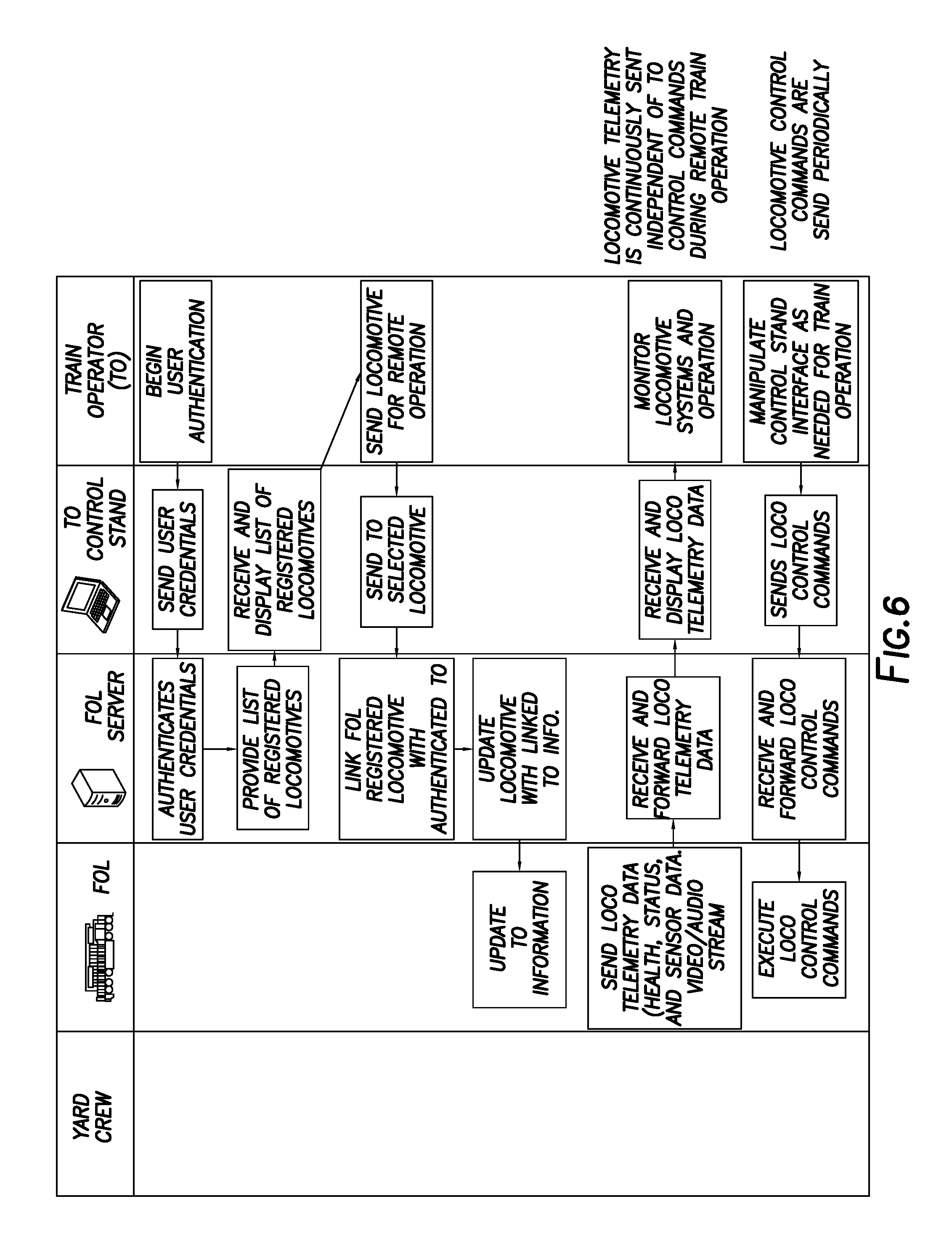
[0015] FIG. 6 is an activity diagram showing the process for train operator registration and the remote locomotive control loop.
DETAILED DESCRIPTION OF THE INVENTION
[0016] System Overview.
[0017] The present system enables control and operation of trains engaged in line-of-road revenue-service operation by train operators (TO) that are not physically present on the train. The present invention is a Flexible Operator Location (FOL) system offering railroads flexibility in the location from which trains are controlled. The TOs controlling the FOL-equipped trains may be located at a centralized control center, or at some other remote, or a "flexible" location. The FOL system provides TOs with the information and control capability necessary to operate trains in accordance with railroad operating rules and federal regulations that stipulate safe train handling practices. The FOL is not a standalone system; rather, it operates in conjunction with railroad safety systems, such as Positive Train Control (PTC), and efficiency enhancement systems, such as Energy Management Systems (EMS), to meet railroad operational and efficiency requirements.
[0018] The primary function of the FOL system is to provide a TO with the capability to control a train during line-of-road operation (i.e., main-line, revenue-service operation) from a remote location. The FOL system provides sufficient capability to allow the train operator to comply with railroad operating rules and practices during line-of-road operations. The FOL system provides sufficient capability for the TO to satisfy operating responsibilities defined by railroad operating practices and operating policies (e.g., special instructions, timetables, hazardous materials instructions, air brake and train handling instructions, and general orders). FIG. 1 illustrates the FOL system's use case diagram detailing the TO's interactions with the FOL system. The TO, the primary user of the FOL system, must be able to control, interact and monitor the locomotive, while maintaining communication with additional railroad employees.
[0019] The FOL system enables an operator to operate a train from a centralized location and is expected to improve both safety and operational efficiency. Multiple safety improvements are possible by implementing the proposed system. First, the proposed system provides railroads the ability to swap crews at any time, irrespective of train location, reducing fatigue and overtime hours. Secondly, the proposed system provides railroads the ability to use a higher quality communication link amongst railroad users than the often-distorted 160 MHz voice radios. Finally, the proposed system allows for improved crew oversight and potential automation of certain functions.
[0020] The ability to change crews at any time will also improve operational efficiency by increasing system capacity by reducing the time lost to support current crew change policies. Additional cost reductions can be expected from crew travel, lodging, per-diem, crew held-away and other costs to support continuous revenue-service operations.
[0021] The following is a description of the changes required for revenue-service FOL system operations, including capability changes, communication changes, interface changes, personnel changes, and operational changes. The FOL system interfaces with existing and to-be-developed onboard systems to provide an operator in a centralized location the ability to safely operate a locomotive per railroad operating rules and policies. In this mode of operation, the FOL system is the link between the TO and the locomotive, allowing the TO to control and monitor the status of a locomotive from a centralized location with little to no cab presence.
[0022] The onboard FOL system relays information between the TO and locomotive through a backhaul and wireless communication network. The video feed and the locomotive controls and indications operate on a communication network that considers stringent latency requirements and manages throughput limitations. Information is transmitted over the backhaul network for the TO to monitor and control in accordance with the railroad's operating rules.
[0023] A TO 10 controlling a locomotive 12 interfaces with the TO control stand 42 instead of the locomotive cab. The control stand 42 provides the TO 10 with the status and control interfaces necessary to safely operate the locomotive 12 in accordance with the operating rules. The FOL system 20 provides the TO 10 with the locomotive's streaming sensory information, including video 36 and audio, as needed to allow the TO 10 to perform duties as defined by railroad operating practices and policies.
[0024] The onboard FOL system 30 architecture is shown in FIG. 2. Each locomotive is equipped with FOL locomotive equipment (or locomotive control unit). The locomotive control unit includes an onboard FOL computer (OFC) 32 and interfaces with other locomotive onboard systems. As shown in FIG. 2, the Energy Management System (EMS) 37 assists with train control through automation of throttle, dynamic brake, and asynchronous control of the distributed power system. The EMS 37 can be enhanced to include the control of automatic and independent air brake and engine controls (e.g., isolate, engine start/stop) with the goal of providing automation of movement from zero speed start to zero speed stop. The FOL Communication Manager 34 manages routing of FOL messages through one or more communication networks. The Locomotive Command Control Module (LCCM) 35 provides an interface to support command and control of locomotive and train systems such as the train line, cab controls, electronic air brake (EAB) system, Distributed Power (DP), and Automatic Engine Start Stop (AESS) controls (e.g., via a Locomotive Interface Gateway, or LIG 33). The Positive Train Control (PTC) system 38 is a safety system that prevents train to train collisions, train overspeed derailments, encroachment of trains into established work zones, and train movement through a switch in the incorrect position. The onboard FOL computer (OFC) 32 includes a number of onboard FOL components that accumulate locomotive health and status information to be reported to the TO, and distribute TO commands to appropriate onboard control systems. A number of sensors 39 are used to provide additional operating information for safe train handling.
[0025] Conventional train operation is performed by train crews located in the lead locomotive of the train, whereas the FOL system 20 allows trains to be controlled by TOs 10a-10c that are not physically present on the train 12a-12c. This results in differences between the responsibilities of conventional train crews and a remote TO 10. In particular, responsibilities assigned to a train crew that requires a physical presence on a train cannot be performed by a TO 10 controlling a train 12 via the FOL system 20. Some of the duties performed by conventional train crews that cannot be performed by a TO 10 may be performed by train-borne, or wayside sensors and automated systems that process and automatically react to sensor data. Over-the-road support personnel perform duties that require presence on or near a FOL-controlled train that cannot otherwise be performed by sensors and systems on the locomotive. The use of the FOL system 20 will not impact the overall management of train movement over the railroad. The FOL system 20 does affect the roles and responsibilities of personnel operating individual trains. Railroads will need revised operating rules and policies to define the role of TOs and over-the-road support personnel when trains are operated with the FOL system. This includes changes to responsibilities of personnel supporting operations in the event of a FOL system failure.
[0026] Functional Description of the FOL System.
[0027] The following section is to provide an operational understanding of the present FOL system 20. The purpose of the FOL system 20 is to allow trains 12a-12c involved in line of road operations to be controlled by operators 10a-10c at remote locations. The FOL system 20 integrates with existing locomotive systems and railroad infrastructure to provide functions necessary to allow TOs 10a-10c to safely and efficiently operate trains 12a-12c from a remote location. The FOL system 20 provides, or interacts with other locomotive systems, including the operator-to-locomotive control loop data, locomotive-to-operator feedback loop data, locomotive operator assistance and locomotive automation functions, to allow train operation consistent with railroad operating rules and operating practices. The functions of the FOL system 20 are divided into the following function groups: (1) FOL system management functions; (2) train control functions; and (3) train monitoring functions.
[0028] The FOL system management functions are responsible for system health and managing sessions between authorized TOs 10a-10c and properly conditioned and configured FOL-equipped locomotives 12a-12c. FOL system management functions include user authentication, segment initialization, system maintenance, and TO link management.
[0029] User authentication is the process by which personnel are verified to be authorized to access FOL system functions. This dynamically establishes a virtual link between a TO 10a-10c at a control stand 42a-42c and a select train 12a-12c with two-way communications via the server 44. The FOL system implements multi-level access privileges that only allow users access to FOL functions that their user class is authorized to use. User classes include train operators, yard personnel, utility workers, and maintenance personnel. User authentication may be implemented by the FOL system 20, or by an ancillary system that manages authentication of multiple railroad systems (i.e. a railroad authentication system may manage user authentication for FOL as well as other systems, such as PTC).
[0030] System initialization is the set of processes by which FOL segments are prepared for operation. Segment initialization processes include but are not limited to: verification of segment hardware integrity; verification of segment operating system integrity; verification of segment software integrity; startup of segment software components; verification of segment configurable parameters; verification of connectivity of components within the segment; and verification of the interface with communication segment. Successful completion of a system segment instance is necessary before it can operate in the FOL system.
[0031] System maintenance is the set of functions that support system diagnostics and aid in keeping systems segment software and configuration updated. System maintenance functions include but are not limited to segment data logging, segment event logging, software update functions, software configuration functions, and remote diagnostics.
[0032] TO link management is the set of processes that manage the application-to-application connection between TOs and trains operating with the FOL system. TO link management functions ensure that each FOL operated train 12a-12c is receiving instructions from a single TO 10a-10c. TO link management also provides mechanisms for handover of control of a FOL train 12a-12c between two TOs without stopping the train (e.g., at shift changes).
[0033] Train control functions provide the control and feedback processes necessary for train operation by a TO 10 at a remote location. FOL train control functions provide the TO 10 with direct train control and assisted train control. Direct train control and assisted train control are not separate modes of operation, but are used in conjunction with one another in a manner consistent with conventional train control by a train crew physically present on a locomotive.
[0034] Direct train control functions provide the TO 10 the ability to interact with locomotive control systems in a manner consistent with a train crew physically present on a locomotive. These locomotive systems include throttle, dynamic brake, train brake, locomotive independent brake, sand, locomotive alarms, distributed power control, and PTC.
[0035] Assisted train control functions provide a TO 10 with tools to optimize train handling efficiency and safety. These functions allow train-borne systems, such as EMS, to manage train control settings (e.g., a throttle and brakes) to reach and maintain target speeds set by the TO. Assisted train control functions may also automatically react to dynamic conditions that require immediate changes to train control system settings.
[0036] Train monitoring functions provide the TO 10 and train-borne assisted train control systems with information about the train 12 and the train operating environment that is not directly in the command and control loop of the train. FOL train monitoring functions are provided by sensor systems which provide streams of information or alarms when conditions require a response from the TO or the FOL system. FOL train monitoring information may be provided by train-borne sensor systems and by wayside sensor systems. Sensor systems integrated with the FOL system may include, but are not limited to: (1) Low-latency locomotive video streams capable of providing views to the front, sides, and rear of the locomotive cab as needed to allow a TO to operate a train safely and efficiently; (2) Low-latency locomotive audio streams of locomotive cab environment; (3) Low-latency wayside video providing real time views of critical sites, such as highway/rail interfaces, that a train is approaching; (4) Train dynamics monitor that provides information on train impacts and vibrations that indicate conditions requiring a TO to adjust train handling; and (5) On-track obstruction hazard detection that provides information or alarms on objects fouling the track that may represent a hazard to a train.
[0037] The FOL system 20 is used to support line-of-road operations where the railroad operating infrastructure is available to support FOL system requirements. FOL requirements on railroad infrastructure include: (1) PTC wayside infrastructure; (2) data communication infrastructure to support FOL command and control functions; and (3) wireless infrastructure suitable for near real-time video streaming of locomotive and wayside video (e.g. 5G).
[0038] System Segments.
[0039] A potential FOL system architecture is shown in FIG. 3. The FOL onboard segment 30 is centered around the OFC 32 and provides the interface to monitor the locomotive 12 status and conduct the control functions performed by the TO 10. FOL onboard functions may include the following: (1) gathering locomotive system information available to the local operator and streaming this information to the TO; (2) gathering sensory information needed for safe train operation and streaming this information to the TO; (3) gathering PTC information and sending it to the TO; (4) providing a PTC system interface for the TO 10 to interact with the PTC onboard system 38; (5) gathering standard locomotive alarms and sending them to the TO; (6) accepting TO command messages and communicating TO commands to the locomotive control systems; (7) monitoring locomotive system health, or obtain locomotive system health information from appropriate locomotive subsystems; (8) providing a fail-safe mechanism for onboard system-initiated controlled train stop; and (9) providing a mechanism for TO-initiated emergency brake application.
[0040] The FOL communication segment 50 links the TO 10 to the onboard FOL system 20 through a backhaul and wireless network. Overall communication latency and throughput need to be suitable to support FOL operations. Information to be transported via the communication network include, but are not limited to TO-initiated throttle changes, TO-initiated brake applications, TO-defined speed targets, sensor information with an emphasis on video requirements, system health messages, locomotive/consist status, PTC alerts/acknowledgements, and system initialization and user authentication messages.
[0041] The backhaul network routes FOL system messages between wayside base stations and the TO Control Stand (TOCS) 42. Sufficient design characteristics will be implemented to support the high-volume of streaming messages transmitted between all FOL locomotives 12a-12c and control stands 42a-42c in operation. Locomotive and wayside locations can be equipped with wireless communication networks to support the bi-directional throughput requirements for control/system messages and streaming video, audio, and sensor feeds. Control/system messages and streaming sensor feeds may have separate communication networks to reduce latency and limit bandwidth consumption.
[0042] The components within the FOL back office segment 40 include the FOL server 44 and TOCSs 12a-12c that will provide the TO 10 with an operational interface to the FOL system 20 during line-of-road operations, as illustrated in FIG. 5. The FOL server's primary function is to manage and route locomotive system information between the TOCS 42 and FOL locomotive 12. The FOL server 44 performs the following functions: (1) authentication of users; (2) authentication of FOL locomotive platform; (3) verification of FOL locomotive software; (4) verification of FOL locomotive 12 conditioning; (5) management of operator/locomotive linking; (6) management of locomotive handover between operators (i.e., "hot-swap" of operators at end of shift); and (7) routing of messages between operators 10a-10c and linked locomotives 12a-12c.
[0043] The TOCS 42a-42c provides the Human Machine Interface (HMI) for the TO 10 to monitor and control the FOL system 20. Control stand 42 includes displays and interfaces that make locomotive audio, video, sensor data and system information, and critical operating and system alerts readily available for the TO 10 to make any necessary control changes (e.g., speed adjustments, PTC responses, brake applications, etc.) to the FOL-controlled locomotive 12. The TOCS 42 also provides the TO 10 with an interface to the railroad 160 MHz voice radio network 46, and other voice communication network as defined by the implementing railroad, to comply with railroad operating rules and practices and provide the ability to communicate with railroad personnel 14 including, but not limited to, train dispatchers, yardmasters, employees in charge (EICs), talker defect detectors, and other nearby locomotives. TOCS functions include providing user input controls suitable for the locomotive control, user interaction with the PTC system 38, and train operation. Locomotive control may include emulation of conventional locomotive cabstand to support direct control of the locomotive by the operator as well as a user interface to allow the operator to set train speed targets and train stop targets for train control managed by the locomotive energy management system 37. Other TOCS functions include, but are not limited to: providing locomotive and train system feedback displayed in a manner consistent with locomotive onboard displays; providing real-time FOL locomotive video display as necessary to satisfy railroad operating rules and regulatory requirements; providing real-time FOL locomotive audio as necessary to satisfy railroad operating rules and regulatory requirements; providing additional locomotive sensor or locomotive environment sensory information as needed to support operational safety and efficiency requirements; providing user interface to control FOL locomotive video footage as necessary to satisfy railroad operating rules and regulatory requirements; 160 MHz voice radio interface 46; and other voice communication as defined by the deploying railroad.
[0044] The FOL communication networks 50 route messages between the TOCS 42 and OFC 32. Locomotive information, control messages, and video feeds are managed to support the high-throughput, low-latency needs of the system. FIG. 4 illustrates the system's data flow from the TO point-of-view. The TOCS 42 will be authenticated to receive information from a specific FOL locomotive 12a-12c. This authentication is used by the FOL server 44 to properly route FOL onboard information to the correct TOCS 42a-42c. FIG. 5 is an activity diagram showing the process for locomotive system initialization and registration. FIG. 6 is an activity diagram showing the process for train operator registration and the remote locomotive control loop.
[0045] The above disclosure sets forth a number of embodiments of the present invention described in detail with respect to the accompanying drawings. Those skilled in this art will appreciate that various changes, modifications, other structural arrangements, and other embodiments could be practiced under the teachings of the present invention without departing from the scope of this invention as set forth in the following claims.
* * * * *
D00000
D00001
D00002
D00003
D00004
D00005
D00006
XML
uspto.report is an independent third-party trademark research tool that is not affiliated, endorsed, or sponsored by the United States Patent and Trademark Office (USPTO) or any other governmental organization. The information provided by uspto.report is based on publicly available data at the time of writing and is intended for informational purposes only.
While we strive to provide accurate and up-to-date information, we do not guarantee the accuracy, completeness, reliability, or suitability of the information displayed on this site. The use of this site is at your own risk. Any reliance you place on such information is therefore strictly at your own risk.
All official trademark data, including owner information, should be verified by visiting the official USPTO website at www.uspto.gov. This site is not intended to replace professional legal advice and should not be used as a substitute for consulting with a legal professional who is knowledgeable about trademark law.