Trailer Backup Assist System With Predictive Hitch Angle Functionality
Hu; Zheng ; et al.
U.S. patent application number 15/693999 was filed with the patent office on 2019-03-07 for trailer backup assist system with predictive hitch angle functionality. This patent application is currently assigned to Ford Global Technologies, LLC. The applicant listed for this patent is Ford Global Technologies, LLC. Invention is credited to Michael Hafner, Zheng Hu, John P. Joyce, Erick Michael Lavoie, Donald Jacob Mattern, Thomas Edward Pilutti, Darrel Alan Recker, Eric Hongtei Tseng, Li Xu.
| Application Number | 20190071088 15/693999 |
| Document ID | / |
| Family ID | 65364237 |
| Filed Date | 2019-03-07 |


View All Diagrams
| United States Patent Application | 20190071088 |
| Kind Code | A1 |
| Hu; Zheng ; et al. | March 7, 2019 |
TRAILER BACKUP ASSIST SYSTEM WITH PREDICTIVE HITCH ANGLE FUNCTIONALITY
Abstract
A trailer backup assist system is provided herein. The system includes a calibration feature for calibrating an imaging device used for hitch angle detection. The system also employs multiple hitch angle detection methods, a number of which may run in parallel to increase the intervals at which a hitch angle can be measured. The system additionally includes a predictive feature in which a hitch angle can be predicted in instances where a trailer sensing device fails. The system is further configured to estimate a trailer length and generate steering commands that are invariant to the estimated trailer length under certain conditions.
| Inventors: | Hu; Zheng; (Farmington Hills, MI) ; Lavoie; Erick Michael; (Dearborn, MI) ; Recker; Darrel Alan; (Ypsilanti, MI) ; Joyce; John P.; (West Bloomfield, MI) ; Mattern; Donald Jacob; (Canton, MI) ; Hafner; Michael; (Ann Arbor, MI) ; Xu; Li; (Northville, MI) ; Tseng; Eric Hongtei; (Canton, MI) ; Pilutti; Thomas Edward; (Ann Arbor, MI) | ||||||||||
| Applicant: |
|
||||||||||
|---|---|---|---|---|---|---|---|---|---|---|---|
| Assignee: | Ford Global Technologies,
LLC Dearborn MI |
||||||||||
| Family ID: | 65364237 | ||||||||||
| Appl. No.: | 15/693999 | ||||||||||
| Filed: | September 1, 2017 |
| Current U.S. Class: | 1/1 |
| Current CPC Class: | G06T 7/60 20130101; G06T 11/60 20130101; G06T 7/74 20170101; G06T 2207/10016 20130101; B60R 2300/80 20130101; G06T 7/73 20170101; B60R 1/00 20130101; B60W 10/20 20130101; G06T 7/13 20170101; B60D 1/245 20130101; B60R 2300/307 20130101; G06T 2207/30264 20130101; B60D 1/62 20130101; G06T 7/80 20170101; B60W 10/18 20130101; B60W 2710/20 20130101; B62D 1/22 20130101; B62D 13/06 20130101; B62D 15/027 20130101; B60K 35/00 20130101; B60W 2710/18 20130101; B60W 30/18036 20130101 |
| International Class: | B60W 30/18 20060101 B60W030/18; B60R 1/00 20060101 B60R001/00; B62D 13/06 20060101 B62D013/06; B60D 1/24 20060101 B60D001/24; B62D 1/22 20060101 B62D001/22; B60W 10/20 20060101 B60W010/20; B60W 10/18 20060101 B60W010/18; B60K 35/00 20060101 B60K035/00; G06T 7/13 20060101 G06T007/13; G06T 7/73 20060101 G06T007/73; G06T 7/80 20060101 G06T007/80; G06T 11/60 20060101 G06T011/60 |
Claims
1. A calibration method comprising the steps of: using an imaging device to capture an image of a rear bumper; and providing a controller configured to: process the captured image; identify a boundary separating the rear bumper from a ground; compare the identified boundary to an ideal boundary; and determine an offset between the identified boundary and the ideal boundary.
2. The calibration method of claim 1, wherein the ideal boundary comprises a continuous line.
3. The calibration method of claim 1, wherein the ideal boundary comprises a line having a break.
4. The calibration method of claim 1, wherein the ideal boundary is overlaid onto the captured image.
5. The calibration method of claim 1, wherein the offset is defined by a vector having a horizontal component, a vertical component, and a rotational component.
6. The calibration method of claim 4, wherein the controller determines the offset by iterating on candidates for each of the horizontal, vertical, and rotational components until the identified boundary overlaps with the ideal boundary.
7. The calibration method of claim 1, wherein the controller is further configured to generate a warning if the offset is unable to be determined.
8. A trailer backup assist system comprising: a device configured to sense a trailer; and a controller configured to determine a hitch angle between a vehicle and the trailer based on data provided by the device, wherein if the device fails, the controller predicts the hitch angle based on a last known hitch angle, a last known angular velocity of the trailer, and an execution cycle time.
9. The trailer backup assist system of claim 8, wherein the device comprises an imaging device and the controller is configured to predict the hitch angle if the imaging device becomes obstructed or otherwise fails.
10. The trailer backup assist system of claim 8, wherein the controller is further configured to predict the hitch angle up until an error band reaches a threshold.
11. The trailer backup assist system of claim 8, wherein the controller is further configured to determine an upper and lower error band of the predicted hitch angle, and enact a countermeasure if the upper error band reaches a maximum controllable hitch angle or the lower error band reaches a minimum controllable hitch angle, whichever comes first.
12. The trailer backup assist system of claim 11, wherein the upper and lower error bands are each determined based on a predicted hitch angle, an initial degree error at the moment the device fails, an accumulative vehicle travel distance, and a trailer length.
13. The trailer backup assist system of claim 11, wherein the countermeasure comprises at least one of steering the vehicle to keep from exceeding the maximum controllable hitch angle or the minimum controllable hitch angle and reducing a speed of the vehicle.
14. The trailer backup assist system of claim 8, wherein the last known angular velocity is based on an angular velocity that is adjusted by a percentage error.
15. A method of determining hitch angle between a vehicle and a trailer, comprising the steps of: selecting at least one hitch angle detection method amongst a plurality of hitch angle detection methods; using the selected at least one hitch angle detection method to determine a hitch angle between a vehicle and a trailer; and transitioning to another hitch angle detection method in the event the selected at least one hitch angle detection method becomes unavailable.
16. The method of claim 15, wherein the plurality of hitch angle detections methods each employ imager-based hitch angle detection.
17. The method of claim 15, wherein the plurality of hitch angle detection methods are ranked based on a confidence score assigned to each hitch angle detection method, and wherein the at least one selected hitch angle detection comprises an available hitch angle detection method having the highest confidence score.
18. The method of claim 17, further comprising the step of limiting the speed of the vehicle based on the confidence score assigned to the at least one selected hitch angle detection method.
19. The method of claim 15, further comprising the step of predicting the hitch angle during the transitioning between the at least one selected hitch angle detection method and another hitch angle detection method or if each of the plurality of hitch angle detection methods become unavailable.
20. The method of claim 15, further comprising the step of using the determined hitch angle to control at least one of a hitch angle operating range, a speed limit of the vehicle, and the curvature of a backing path of the trailer.
21. A trailer backup assist system comprising: a steering input device configured to provide a curvature command based on user input; and a controller configured to estimate a trailer length based on a vehicle and trailer yaw rate and generate a steering command based on the estimated trailer length, the curvature command, a maximum steering angle, and a vehicle speed, wherein the generated steering command is invariant to the estimated trailer length under certain conditions.
22. The trailer backup assist system of claim 21, wherein the steering input device comprises a rotatable knob configured to allow a user to input a desired direction and curvature of a backing path of a trailer backed by a vehicle.
23. The trailer backup assist system of claim 21, wherein the controller comprises a curvature input scaling module configured to scale the curvature command by a maximum effective curvature to generate a curvature input based on the maximum steering angle and the estimated trailer length.
24. The trailer backup assist system of claim 22, wherein the controller further comprises a curvature mapping module configured to generate a reference hitch angle based on the curvature input and the estimated trailer length.
25. The trailer backup assist system of claim 24, wherein the controller further comprises a subtractor configured to subtract an estimated hitch angle from the reference hitch angle to generate a signal provided to a proportional-integral controller configured to generate a control variable, wherein the estimated hitch angle is based on the vehicle and trailer yaw rate.
26. The trailer backup assist system of claim 25, wherein the controller further comprises a hitch angle controller configured to generate the steering angle based on the control variable, the estimated trailer length, and the vehicle speed.
27. The trailer backup assist system of claim 25, wherein a proportional coefficient of the proportional-integral controller is based only on the estimated trailer length such that a transient response of the controller is invariant to the estimated trailer length.
28. The trailer backup assist system of claim 21, wherein the certain conditions comprise one of a zero curvature command, a maximum curvature command, and a minimum curvature command.
Description
FIELD OF THE INVENTION
[0001] The present invention generally relates to systems for assisting an operator in backing a trailer, and more particularly, to systems using imager-based hitch angle detection.
BACKGROUND OF THE INVENTION
[0002] Reversing a vehicle while towing a trailer can be challenging for many drivers, particularly for drivers that drive with a trailer on an infrequent basis or with various types of trailers. Some systems used to assist an operator in backing a trailer rely on hitch angle measurements to determine the position of the trailer relative to the vehicle. Thus, the accuracy and reliability of the hitch angle measurements can be critical to the operation of the trailer backup assist system. In systems employing imager-based hitch angle detection, improper calibration of an imaging device can lead to inaccurate hitch angle measurements. Furthermore, in instances where the imaging device becomes obstructed, such systems may be forced offline and rendered unable to determine a hitch angle between the vehicle and the trailer. To function properly, some systems require a user to input measurements such as trailer length. This is not only cumbersome on the user but may lead to erroneous measurements being inputted to the system. Accordingly, there is a need for a trailer backup assist system that overcomes the problems mentioned above. The present disclosure is intended to satisfy this need.
SUMMARY OF THE INVENTION
[0003] According to a first aspect of the present invention, a calibration method is provided herein. The method includes the steps of: using an imaging device to capture an image of a rear bumper; and providing a controller configured to process the captured image, identify a boundary separating the rear bumper from a ground; compare the identified boundary to an ideal boundary, and determine an offset between the identified boundary and the ideal boundary.
[0004] Embodiments of the first aspect can include any one or a combination of the following features: [0005] the ideal boundary includes a continuous line; [0006] the ideal boundary includes a line having a break; [0007] the ideal boundary is overlaid onto the captured image; [0008] the offset is defined by a vector having a horizontal component, a vertical component, and a rotational component; [0009] the controller determines the offset by iterating on candidates for each of the horizontal, vertical, and rotational components until the identified boundary overlaps with the ideal boundary; and [0010] the controller is further configured to generate a warning if the offset is unable to be determined.
[0011] According to a second aspect of the present invention, a trailer backup assist system is provided. The system includes a device configured to sense a trailer and a controller configured to determine a hitch angle between a vehicle and the trailer based on data provided by the device. If the device fails, the controller predicts the hitch angle based on a last known hitch angle, a last known angular velocity of the trailer, and an execution cycle time.
[0012] Embodiments of the second aspect can include one or a combination of the following features: [0013] the device comprises an imaging device and the controller is configured to predict the hitch angle if the imaging device becomes obstructed or otherwise fails; [0014] the controller is further configured to predict the hitch angle up until an error band reaches a threshold; [0015] the controller is further configured to determine an upper and lower error band of the predicted hitch angle, and enact a countermeasure if the upper error band reaches a maximum controllable hitch angle or the lower error band reaches a minimum controllable hitch angle, whichever comes first; [0016] the upper and lower error bands are each determined based on a predicted hitch angle, an initial degree error at the moment the device fails, an accumulative vehicle travel distance, and a trailer length; [0017] the countermeasure comprises at least one of steering the vehicle to keep from exceeding the maximum controllable hitch angle or the minimum controllable hitch angle and reducing a speed of the vehicle; and [0018] the last known angular velocity is based on an angular velocity that is adjusted by a percentage error.
[0019] According to a third aspect of the present invention, a method of determining hitch angle between a vehicle and a trailer is provided. The method includes the steps of: selecting at least one hitch angle detection method amongst a plurality of hitch angle detection methods; using the selected at least one hitch angle detection method to determine a hitch angle between a vehicle and a trailer; and transitioning to another hitch angle detection method in the event the selected at least one hitch angle detection method becomes unavailable.
[0020] Embodiments of the third aspect can include one or a combination of the following features: [0021] the plurality of hitch angle detections methods each employ imager-based hitch angle detection; [0022] the plurality of hitch angle detection methods are ranked based on a confidence score assigned to each hitch angle detection method, and wherein the at least one selected hitch angle detection includes an available hitch angle detection method having the highest confidence score; [0023] the step of limiting the speed of the vehicle based on the confidence score assigned to the at least one selected hitch angle detection method; [0024] the step of predicting the hitch angle during the transitioning between the at least one selected hitch angle detection method and another hitch angle detection method or if each of the plurality of hitch angle detection methods become unavailable; and [0025] the step of using the determined hitch angle to control at least one of a hitch angle operating range, a speed limit of the vehicle, and the curvature of a backing path of the trailer.
[0026] According to a fourth aspect of the present invention, a trailer backup assist system is provided. A steering input device is configured to provide a curvature command based on user input. A controller is configured to estimate a trailer length based on a vehicle and trailer yaw rate. The controller generates a steering command based on the estimated trailer length, the curvature command, a maximum steering angle, and a vehicle speed. The generated steering command is invariant to the estimated trailer length under certain conditions.
[0027] Embodiments of the fourth aspect can include one or a combination of the following features: [0028] the steering input device includes a rotatable knob configured to allow a user to input a desired direction and curvature of a backing path of a trailer backed by a vehicle; [0029] the controller includes a curvature input scaling module configured to scale the curvature command by a maximum effective curvature to generate a curvature input based on the maximum steering angle and the estimated trailer length; [0030] the controller further includes a curvature mapping module configured to generate a reference hitch angle based on the curvature input and the estimated trailer length; [0031] the controller further includes a subtractor configured to subtract an estimated hitch angle from the reference hitch angle to generate a signal provided to a proportional-integral (PI) controller configured to generate a control variable, wherein the estimated hitch angle is based on the vehicle and trailer yaw rate; [0032] the controller further includes a hitch angle controller configured to generate the steering angle based on the control variable, the estimated trailer length, and the vehicle speed; [0033] the controller further includes a proportional coefficient of the PI controller based only on the estimated trailer length such that a transient response of the controller is invariant to the estimated trailer length; and [0034] the certain conditions include one of a zero curvature command, a maximum curvature command, and a minimum curvature command.
[0035] These and other features, advantages, and objects of the present invention will be further understood and appreciated by those skilled in the art by reference to the following specification, claims, and appended drawings.
BRIEF DESCRIPTION OF THE DRAWINGS
[0036] In the drawings:
[0037] FIG. 1 is a top perspective view of a vehicle attached to a trailer with one embodiment of a hitch angle sensor for operating a trailer backup assist system;
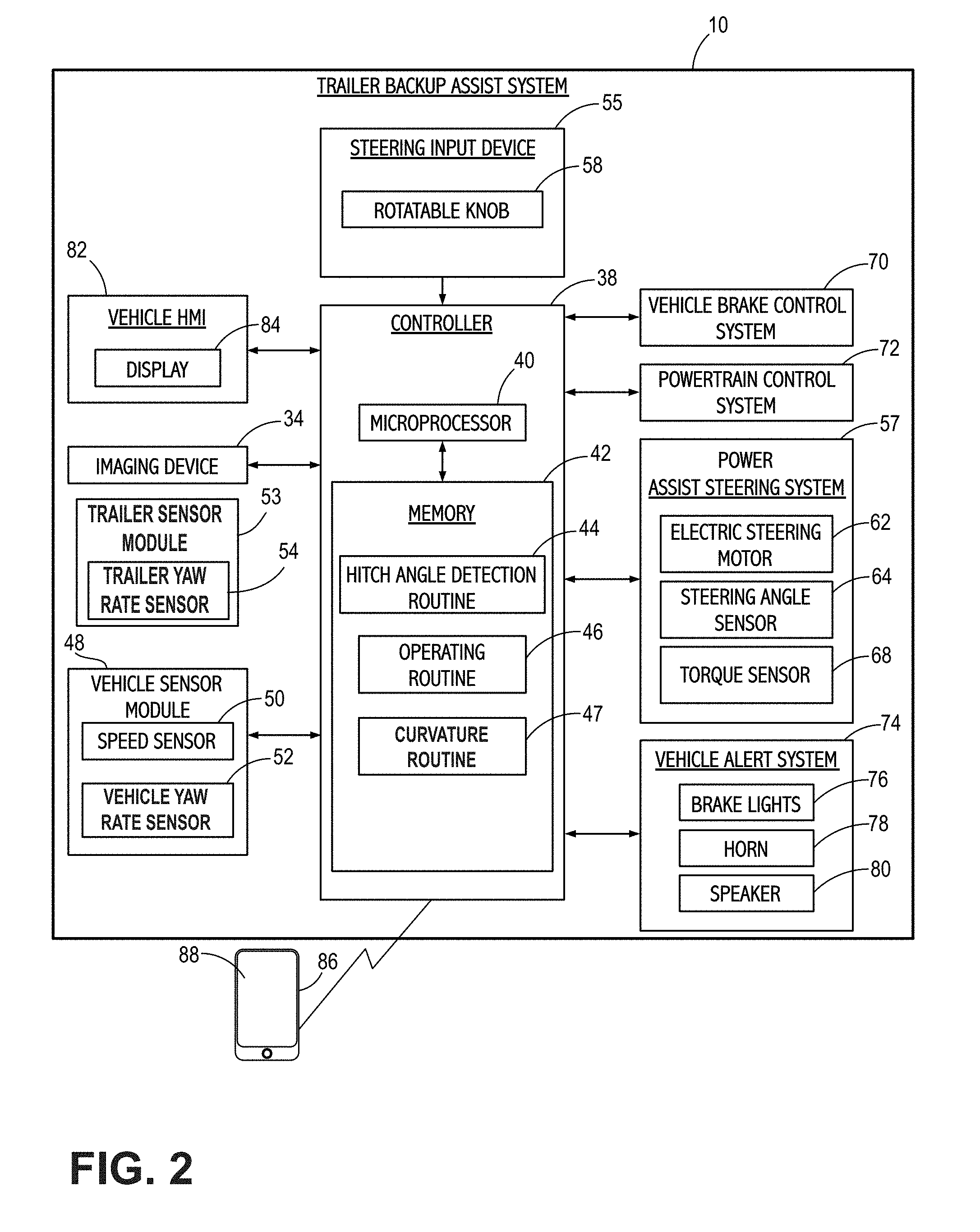
[0038] FIG. 2 is a block diagram illustrating one embodiment of the trailer backup assist system;
[0039] FIG. 3 illustrates a kinematic relationship between the vehicle and the trailer;
[0040] FIG. 4 illustrates a steering input device having a rotatable knob for operating the trailer backup assist system;
[0041] FIG. 5 illustrates the rotatable knob for selecting a desired curvature of a trailer and a corresponding schematic diagram illustrating the vehicle and the trailer with various trailer curvature paths correlating with desired curvatures that may be selected;
[0042] FIG. 6 is a flow diagram of a method for calibrating an imaging device of the vehicle;
[0043] FIG. 7 illustrates a captured image showing the edges of a rear bumper of the vehicle;
[0044] FIG. 8 illustrates a captured image in which an ideal boundary between the rear bumper and a ground is identified according to one embodiment;
[0045] FIG. 9 illustrates a captured image in which the ideal boundary is identified according to an alternative embodiment;
[0046] FIG. 10 illustrates a captured image in which an identified boundary is compared to the ideal boundary to determine an offset used in calibrating the imaging device;
[0047] FIG. 11 is a graph illustrating the deviation between actual hitch angle and predicted hitch angle over a vehicle travel distance;
[0048] FIG. 12 is a flow diagram of a method for determining a hitch angle between the vehicle and the trailer;
[0049] FIG. 13 illustrates a curvature input scaling module used to scale a curvature command inputted using the steering input device;
[0050] FIG. 14 illustrates a controller of the trailer backup assist system including the curvature input scaling module; and
[0051] FIG. 15 is a graph illustrating a family of closed-loop equilibria as a function of the curvature command for a number of estimated trailer lengths.
DETAILED DESCRIPTION OF THE PREFERRED EMBODIMENTS
[0052] For purposes of description herein, it is to be understood that the disclosed trailer backup assist system and the related methods may assume various alternative embodiments and orientations, except where expressly specified to the contrary. It is also to be understood that the specific devices and processes illustrated in the attached drawings, and described in the following specification, are simply exemplary embodiments of the inventive concepts defined in the appended claims. While various aspects of the trailer backup assist system and the related methods are described with reference to a particular illustrative embodiment, the disclosed invention is not limited to such embodiments, and additional modifications, applications, and embodiments may be implemented without departing from the disclosed invention. Hence, specific dimensions and other physical characteristics relating to the embodiments disclosed herein are not to be considered as limiting, unless the claims expressly state otherwise.
[0053] As used herein, the term "and/or," when used in a list of two or more items, means that any one of the listed items can be employed by itself, or any combination of two or more of the listed items can be employed. For example, if a composition is described as containing components A, B, and/or C, the composition can contain A alone; B alone; C alone; A and B in combination; A and C in combination; B and C in combination; or A, B, and C in combination.
[0054] Referring to FIGS. 1 and 2, reference numeral 10 generally designates a trailer backup assist (TBA) system for assisting a vehicle 12 in reversing a trailer 14. The vehicle 12 is embodied as a pickup truck that is pivotally attached to one embodiment of the trailer 14 that has a box frame 16 with an enclosed cargo area 18, a single axle 20 operably coupled to wheels 22 and 24, and a tongue 26 longitudinally extending forward from the enclosed cargo area 18. The illustrated trailer 14 also has a trailer hitch connector in the form of a coupler assembly 28 that is connected to a vehicle hitch connector in the form of a hitch ball 30 and drawbar 31. The coupler assembly 28 latches onto the hitch ball 30 to provide a pivoting hitch 32 that allows for articulation of a hitch angle (e.g., hitch angle .gamma.; FIG. 3) between the vehicle 12 and the trailer 14. As defined herein, the hitch angle corresponds to the angle formed between the center longitudinal axis of the vehicle 12 and of the trailer 14. It should be appreciated that additional embodiments of the trailer 14 may alternatively couple with the vehicle 12 to provide a pivoting connection, such as by connecting with a fifth wheel connector. It is also contemplated that additional embodiments of the trailer 14 may include more than one axle and may have various shapes and sizes configured for different loads and items, such as a boat trailer or a flatbed trailer.
[0055] The TBA system 10 also includes an imaging device 34 located at the rear of the vehicle 12 and configured to image a rear-vehicle scene. The imaging device 34 may be centrally located at an upper region of a vehicle tailgate 35 such that the imaging device 34 is elevated relative to the tongue 26 of the trailer 14. The imaging device 34 has a field of view 36 located and oriented to capture one or more images that may include the tongue 26 of the trailer 14 and the hitch ball 30, among other things. Image data is supplied to a controller 38 of the TBA system 10 and is processed by the controller 38 to determine the hitch angle between the vehicle 12 and the trailer 14. Additional information regarding image-based hitch angle detection and associated methodologies can be found in commonly assigned U.S. Pat. No. 9,610,975 to Hu et al., issued Apr. 4, 2017, and entitled "HITCH ANGLE DETECTION FOR TRAILER BACKUP ASSIST SYSTEM," the entire disclosure of which is incorporated by reference herein.
[0056] The controller 38 is configured with a microprocessor 40 and/or other analog and/or digital circuitry for processing one or more logic routines stored in a memory 42. The logic routines may include a hitch angle detection routine 44, an operating routine 46, and a curvature routine 47. Information from the imaging device 34 or other components of the TBA system 10 can be supplied to the controller 38 via a communication network of the vehicle 12, which can include a controller area network (CAN), a local interconnect network (LIN), or other conventional protocols used in the automotive industry. It should be appreciated that the controller 38 may be a stand-alone dedicated controller or may be a shared controller integrated with the imaging device 34 or other component of the TBA system 10 in addition to any other conceivable onboard or off-board vehicle control systems.
[0057] With respect to the present embodiment, the controller 38 is configured to communicate with a variety of vehicle equipment. The TBA system 10 may include a vehicle sensor module 48 that monitors certain dynamics of the vehicle 12. The vehicle sensor module 48 may generate a plurality of signals that are communicated to the controller 38 such as a vehicle speed signal generated by a speed sensor 50 and a vehicle yaw rate signal generated by a vehicle yaw rate sensor 52. A trailer sensor module 53 is provided that monitors certain dynamics of the trailer 14. The trailer sensor module 53 includes a trailer yaw rate sensor 54 configured to generate a trailer yaw rate signal that is provided to the controller 38.
[0058] A steering input device 55 is provided to enable a driver to control or otherwise modify a desired curvature (e.g., desired curvature 56; FIG. 5) of a backing path of the trailer 14. The steering input device 55 may be communicatively coupled to the controller 38 in a wired or wireless manner and provides the controller 38 with input defining the desired curvature of the backing path of the trailer 14. In response to the input, the controller 38 generates corresponding steering commands that are supplied to a power assist steering system 57 of the vehicle 12. In one embodiment, the steering input device 55 includes a rotatable knob 58 operable between a number of rotated positions that each provide an incremental change to the desired curvature 56 of the backing path of the trailer 14.
[0059] The knob 58 may be rotatable about a rotational axis extending through a top surface or face of the knob 58. In other embodiments, the knob 58 may be rotatable about a rotational axis extending substantially parallel to a top surface or face of the knob 58. Furthermore, the steering input device 55, according to additional embodiments, may include alternative devices for providing the desired input, such as a joystick, a keypad, a series of depressible buttons or switches, a sliding input device, various user interfaces on a touch-screen display, a vision-based system for receiving gestures, a control interface on a portable device, and other conceivable input devices as generally understood by one having ordinary skill in the art. It is contemplated that the steering input device 55 may also function as an input device for other features, such as providing inputs for other vehicle features or systems.
[0060] According to one embodiment, the controller 38 of the TBA system 10 may control the power assist steering system 57 of the vehicle 12 to operate steered wheels 60 of the vehicle 12 for moving the vehicle 12 in such a manner that the trailer 14 reacts in accordance with the desired curvature 56 of the backing path of the trailer 14. The power assist steering system 57 may be an electric power-assisted steering (EPAS) system that includes an electric steering motor 62 for turning the steered wheels 60 to a steering angle based on a steering command generated by the controller 38, whereby the steering angle may be sensed by a steering angle sensor 64 of the power assist steering system 57 and provided to the controller 38. The steering command may be provided for autonomously steering the vehicle 12 during a backup maneuver and may alternatively be provided manually via a rotational position (e.g., a steering wheel angle) of a steering wheel 66 or the rotatable knob 58. However, in some embodiments, the steering wheel 66 of the vehicle 12 may be mechanically coupled with the steered wheels 60 of the vehicle 12, such that the steering wheel 66 moves in concert with steered wheels 60 via an internal torque, thereby preventing manual intervention with the steering wheel 66 during autonomous steering of the vehicle 12. In such instances, the power assist steering system 57 may include a torque sensor 68 that senses torque (e.g., gripping and/or turning) on the steering wheel 66 that is not expected from autonomous control of the steering wheel 66 and therefore indicative of manual intervention by the driver. In some embodiments, external torque applied to the steering wheel 66 may serve as a signal to the controller 38 that the driver has taken manual control and for the TBA system 10 to discontinue autonomous steering functionality.
[0061] The controller 38 of the TBA system 10 may also communicate with a vehicle brake control system 70 of the vehicle 12 to receive vehicle speed information such as individual wheel speeds of the vehicle 12. Additionally or alternatively, vehicle speed information may be provided to the controller 38 by a powertrain control system 72 and/or the speed sensor 50, among other conceivable means. It is conceivable that individual wheel speeds may be used to determine a vehicle yaw rate, which can be provided to the controller 38 in the alternative, or in addition to, the vehicle yaw rate measured by yaw rate sensor 52 of the vehicle sensor module 48. In some embodiments, the controller 38 may provide braking commands to the vehicle brake control system 70, thereby allowing the TBA system 10 to regulate the speed of the vehicle 12 during a backup maneuver of the trailer 14. It should be appreciated that the controller 38 may additionally or alternatively regulate the speed of the vehicle 12 via interaction with the powertrain control system 72.
[0062] Through interaction with the power assist steering system 57, the vehicle brake control system 70, and/or the powertrain control system 72 of the vehicle 12, the potential for unacceptable trailer backup conditions can be reduced. Examples of unacceptable trailer backup conditions include, but are not limited to, a vehicle over-speed condition, a high hitch angle rate, hitch angle dynamic instability, a trailer jackknife condition, sensor failure, and the like. In such circumstances, the driver may be unaware of the failure until the unacceptable trailer backup condition is imminent or already happening. Therefore, it is disclosed herein that the controller 38 of the TBA system 10 can generate an alert signal corresponding to a notification of an actual, impending, and/or anticipated unacceptable trailer backup condition, and prior to driver intervention, generate a counter measure to prevent such an unacceptable trailer backup condition.
[0063] According to one embodiment, the controller 38 may communicate with one or more devices, including a vehicle alert system 74, which may prompt visual, auditory, and tactile warnings. For instance, vehicle brake lights 76 and vehicle emergency flashers may provide a visual alert and a vehicle horn 78 and/or speaker 80 may provide an audible alert. Additionally, the controller 38 and/or vehicle alert system 74 may communicate with a human machine interface (HMI) 82 of the vehicle 12. The HMI 82 may include a touchscreen vehicle display 84 such as a center-stack mounted navigation or entertainment display capable of displaying images indicating the alert. Such an embodiment may be desirable to notify the driver of the vehicle 12 that an unacceptable trailer backup condition is afoot. Further, it is contemplated that the controller 38 may communicate via wireless communication with one or more electronic portable devices such as portable electronic device 86, which is embodied as a smartphone. The portable electronic device 86 may include a display 88 for displaying one or more images and other information to a user. In response, the portable electronic device 86 may provide feedback information, such as visual, audible, and tactile alerts.
[0064] When the imaging device 34 is installed on the vehicle 12, it is important to minimize errors arising during installation or at a later time. Such errors generally result from improper alignment between the imaging device 34 and the vehicle 12 in terms of yaw, pitch, and roll. These errors may be caused by various factors such as manufacturing variability, part-to-part variability over time, damage to the vehicle, or parts replacement, for example, all of which have the potential of changing the alignment between the imaging device 34 and the vehicle 12. Initially, these errors are calibrated before the imaging device 34 can be used to support functions such as imager-based hitch angle detection. If not properly calibrated, the resultant errors may negatively impact the accuracy and robustness of functions instituted by the imaging device 34.
[0065] Referring to FIG. 6, a flow diagram is shown describing a method 90 of calibrating an imaging device (e.g., image device 34), which is typically mounted to the rear of a vehicle and configured to image a rear-vehicle scene. However, it will be understood that the method 90 may be similarly instituted to calibrate imaging devices located elsewhere on the vehicle.
[0066] At step 95, a benchmark installation is prepared. For example, the benchmark installation includes positioning the imaging device in the ideal orientation relative to the vehicle. In the embodiment of FIG. 1, for instance, the imaging device is ideally mounted to the upper region of a vehicle tailgate 35 and is oriented to capture images of a rear-vehicle scene including the rear bumper. Once the imaging device is ideally positioned, the imaging device is operated to capture an image that includes a rear bumper that is similarly configured as the rear bumper 96 (FIG. 1) of the vehicle 12 at step 100. According to one embodiment, the image is captured against a homogenous background (e.g., an evenly illuminated white wall) or is compiled from a series of images captured while the vehicle is moving at a predefined speed. The speed may be a specific speed or a speed range and is generally selected to prevent excessive vibration of the imaging device and further allow for the ground to be blurred out in the compiled image.
[0067] At step 105, edge detection is conducted on the captured image. For purposes of illustration, FIG. 7 is a sample captured image showing detected edges (e.g., edge 106) of rear bumper 96', which is similarly configured to the rear bumper 96 of the vehicle 12. At step 110, an ideal boundary between the rear bumper and the ground is identified in the captured image based on one or more edges detected at step 105. For purposes of illustration, FIG. 8 shows an ideal boundary 111 identified between the detected edge 106 shown in FIG. 7 and ground 112. As shown, the ideal boundary 111 is a continuous line spanning across the image and separates the rear bumper 96 from the ground 112. In an alternative embodiment, shown in FIG. 9, the ideal boundary 111 contains a central break and is identified from edges only appearing in lower corner portions 113 of the captured image. In other words, a majority portion 114 of the captured image is ignored when identifying the ideal boundary 111. The majority portion generally corresponds to areas of the captured image where a valid boundary is unlikely to be present. Optionally, as shown in FIG. 9, the majority portion 114 includes a lower central area 114' of the captured image to avoid processing areas where a trailer hitch connector is likely to be detected and may possibly corrupt the shape of the ideal boundary 111. By ignoring certain portions of the captured image, the captured image is effectively reduced in size, thereby allowing the ideal boundary 111 to be more quickly identified. In yet another alternative embodiment, the ideal boundary 111 may be generated from computer drawings or the like. At step 115, the ideal boundary 111 and its position are recorded to be later used to calibrate other imaging devices of the same model and similarly installed on identical vehicle models. Thus, it is to be understood that steps 95-115 need only be conducted once per vehicle model. As such, steps 95-115 may be carried out in a lab setting if desired.
[0068] In contrast, steps 120-150 are generally conducted on the assembly line and are repeated for each vehicle of the same model. For purposes of understanding, steps 120-150 will be described with respect to the embodiment of vehicle 12 shown in FIG. 1. At step 120, the ideal boundary 111 and its position, as predetermined at step 110, are provided to controller 38 (e.g., stored on memory 42). Next, at step 125, the controller 38 operates the imaging device 34 to capture an image that includes the rear bumper 96 of the vehicle 12. At step 130, the controller 38 processes the captured image to identify the boundary between the rear bumper 96 of the vehicle 12 and the ground. Once identified, the controller 38 compares the position of the identified boundary to the position of the stored ideal boundary 111. For example, the stored ideal boundary 111 may be overlaid onto the captured image. If the position of the identified boundary overlaps with the position of the stored ideal boundary 111, the installation of the imaging device 34 is complete and no calibration is needed. In other words, the imaging device 34 was installed free of errors and is ready for use. As such, the method 90 ends at step 140.
[0069] Alternatively, if the position of the identified boundary fails to overlap with the position of the stored ideal boundary 111, the controller 38 determines an offset between the identified boundary and the stored ideal boundary 111 at step 145. For purposes of illustration, FIG. 10 is a sample image showing an identified boundary 146 that is offset with respect to the stored ideal boundary 111. In the depicted embodiment, the offset is defined as a vector having a horizontal component X, a vertical component Y, and a rotational component .theta.. It is contemplated that the offset can be determined by iterating on reasonable candidates for each of components X, Y, and .theta. until the identified boundary 146 overlaps with the stored ideal boundary 111 or vice versa. Once the offset has been determined, the calibration of the imaging device 34 is complete and the imaging device 34 is now ready for use. Accordingly, the method 100 ends at step 150.
[0070] It should be appreciated that the imaging device 34 may be calibrated multiple times during the life of the vehicle 12. For example, it is contemplated that the foregoing steps may be executed at regular time intervals, once per ignition cycle, if replacement of the imaging device 34 is detected, and/or if a collision is detected. It is further contemplated that the controller 38 may inhibit calibration of the imaging device 34 in instances where the orientation and/or position of the rear bumper 96 have changed substantially, the shape of the identified boundary 146 is unable to be matched to the stored ideal boundary 111 (typically due to damage or modification of the rear bumper 96), the rear bumper 96 is not securely attached to the vehicle 12, or the imaging device 34 is not securely fixed to the vehicle 12 (e.g., the tailgate 35 is not secure), for example. Additionally or alternatively, the calibration of the imaging device 34 may be inhibited if the values of components X, Y, and 0 exceed a predetermined threshold(s) or if the error between pixels of the boundary and the identified boundary exceed a threshold.
[0071] In the event the controller 38 inhibits calibration of the imaging device 34, a warning may be provided to a user of the TBA system 10. The warning may be generated by the controller 38 and carried out by existing vehicle components such as the display 34, speaker 80, for example, as well as portable electronic device 86. It is contemplated that the warning may be visual, auditory, haptic, or a combination thereof. In instances where damage to the vehicle 12 is detected (e.g., via inertial and/or perimeter sensors), the TBA system 10 may store a corresponding Diagnostic Trouble Code (DTC) and/or warn the user that the imaging device 34 and/or rear bumper 96 may require repair.
[0072] As described herein, the TBA system 10 features imager-based hitch angle detection, among other things. As a downside, there are instances where the imaging device 34 may be obstructed from tracking the trailer 14 or other objects in the imaged scene useful for hitch angle detection. For example, obstruction may occur when debris or other objects are deposited on the lens of the imaging device 34, the imaging device 34 experiences glare due to direct impingement of sunlight, or is unable to reliably image key features in the scene. In such instances where the imaging device 34 becomes obstructed, it is contemplated that the TBA system 10 may report the condition to the driver and may additionally cease imager-based hitch angle detection along with any other functions that rely on the processing of image data. While such instances are generally infrequent, the driver may become frustrated nonetheless if certain functions of the TBA system 10 become unavailable. Accordingly, a solution is needed that minimizes the downtime of image-based hitch angle detection due to the inability of the imaging device 34 to reliably image the scene.
[0073] In such a situation, the TBA system 10 may be configured to predict hitch angles using a "predictive model method," which may be embodied in the hitch angle detection routine 44 and will be described in greater detail below with reference to FIG. 3, which illustrates a kinematic relationship between the vehicle 12 and the trailer 14. To predict a hitch angle, the controller 38 first determines an angular velocity {dot over (.gamma.)} of the trailer 14, which can be determined by the following equation:
.gamma. . = v D sin .gamma. + ( 1 + L D cos .gamma. ) v W tan .delta. , ( 1 ) ##EQU00001##
where: .gamma. is the hitch angle (.beta.-.alpha.) between the vehicle 12 and the trailer 14, .delta. is the steering angle of steered wheels 60 of the vehicle 12, L is the drawbar length between the hitch 32 and a rear axle 155 of the vehicle 12, D is the trailer length between the hitch 32 and effective axle 20 of the trailer 14, W is the wheelbase length between a front axle 157 and the rear axle 155 of the vehicle 12, and .nu. is the longitudinal speed of the vehicle 12. It is to be noted that the function
v W ##EQU00002##
tan .delta. corresponds to the yaw rate of the vehicle 12 and can be otherwise supplied by vehicle yaw rate sensor 52 (FIG. 2).
[0074] In calculating the angular velocity {dot over (.gamma.)} of the trailer 14, it is assumed that the trailer length D, drawbar length L, and wheelbase length W are known. The steering angle .delta. and the longitudinal speed .nu. may be readily provided to the controller 38 by steering angle sensor 64 (FIG. 2) and speed sensor 50 (FIG. 2), respectively. Under normal operating conditions, the hitch angle .gamma. can be determined pursuant to any known imager-based hitch angle detection method. Thus, so long as the imaging device 34 is unobstructed, or in other words, able to reliably track the trailer 14, the controller 38 is able to determine the angular velocity {dot over (.gamma.)} of the trailer 14.
[0075] However, if the imaging device 34 suddenly becomes obstructed such that imager-based hitch angle detection becomes unavailable, the controller 38 can predict the hitch angle based on predetermined information including a last known hitch angle, a last known angular velocity of the trailer 14, and an execution cycle time of the image processor (e.g., microprocessor 40, FIG. 2) as represented by the following equation:
.gamma..sub.p=.gamma..sub.lk+{dot over (.gamma.)}.sub.lkt.sub.c (2)
where: .gamma..sub.p is a predicted hitch angle, .gamma..sub.lk is the last known hitch angle, {dot over (.gamma.)}.sub.lk is the last known angular velocity of the trailer 14, and t.sub.c is the execution cycle time of the image processor. Thus, so long as the controller 38 is able to iterate equation 1 at least once before the imaging device 34 becomes obstructed, the controller 38 will have sufficient information to predict the hitch angle .gamma..sub.p by iterating equation 2. The controller 38 may again calculate the angular velocity {dot over (.gamma.)} of the trailer 14 by substituting the predicted hitch angle .gamma..sub.p into equation 1, followed in turn by again predicting the hitch angle .gamma..sub.p using the recalculated angular velocity {dot over (.gamma.)} as the last known angular velocity {dot over (.gamma.)}.sub.lk in equation 2. Thus, through stepwise reiteration of equations 1 and 2, the controller 38 is able predict the hitch angle in instances where imager-based hitch detection is unavailable or otherwise unreliable.
[0076] The predictive model method outlined above may be implemented for extended durations. However, as time progresses, the predicted hitch angle may begin to deviate from the true or actual hitch angle. Referring to FIG. 11, a graph is shown illustrating the deviation between actual hitch angle and predicted hitch angle over a vehicle travel distance D. For exemplary purposes, the controller 38 begins predicting the hitch angle when the imaging device 34 becomes obstructed at an arbitrary distance D.sub.0. As the vehicle 12 continues to travel, the error band of the predicted hitch angle, shown as upper and lower error bands, start to increase exponentially with respect to the vehicle travel distance D. Thus, hitch angle prediction tends to lose reliability as vehicle travel distance increases. In operation, the controller 38 continues to predict the hitch angle up until the error band reaches a threshold. For example, the controller 38 would stop predicting the hitch angle when the upper error band reaches a maximum controllable hitch angle 160 or the lower error band reaches a minimum controllable hitch angle 162, whichever comes first. In the illustrated embodiment, the upper error band is shown to reach the maximum controllable hitch angle at distance D.sub.max, thus prompting the controller 38 to stop predicting the hitch angle.
[0077] The degree error between the predicted hitch angle and the true hitch angle is determined by the following equation:
e = e 0 s D , ( 3 ) ##EQU00003##
where: e is the degree error, e.sub.0 is an initial degree error at the moment the imaging device 34 becomes obstructed (e.g., 0.5 to 1 degree depending on the accuracy of hitch angle detection), s is an accumulative vehicle travel distance determined by an odometer of the vehicle 12, and D is the trailer length, which is assumed to be known.
[0078] Knowing the degree error e, the error band is determined by the following equations:
.gamma..sup.+=.gamma..sub.p+e (4)
.gamma..sup.-=.gamma..sub.p-e (5)
where: .gamma..sup.+ is the upper error band, .gamma..sup.- is the lower error band, .gamma..sub.p is the predicted hitch angle determined from equation 2, and e is the degree error determined from equation 3. Alternatively, the determination of the upper and lower error bands may include an error adjustment incorporated into each iteration of equation 1. That is, the angular velocity {dot over (.gamma.)} determined using equation 1 is adjusted by a percentage error and the adjusted angular velocity is then used as the last known angular velocity {dot over (.gamma.)}.sub.lk when predicting the hitch angle .gamma..sub.p in equation 2.
[0079] Specifically, with respect to the upper error band .gamma..sup.+, the adjustment made to the angular velocity {dot over (.gamma.)} is given by the following equation:
{dot over (.gamma.)}.sub.adj={dot over (.gamma.)}+|{dot over (.gamma.)}.epsilon.| (6)
With respect to the lower error band .gamma..sup.-, the adjustment made to the angular velocity {dot over (.gamma.)} is given by the following equation:
{dot over (.gamma.)}.sub.adj={dot over (.gamma.)}-|{dot over (.gamma.)}.epsilon.| (7)
where: {dot over (.gamma.)}.sub.adj is an adjusted angular velocity, {dot over (.gamma.)} is the angular velocity determined in equation 1, and .epsilon. is a percentage error and is derived through experimentation. Accordingly, from equations 6 and 7, it can be seen that the adjusted angular velocity {dot over (.gamma.)}.sub.adj associated with the upper and lower error bands will differ and therefore produce different predicted hitch angles .gamma..sub.p when used as the last known angular velocity {dot over (.gamma.)}.sub.lk in equation 2. Thus, equation 2 is iterated twice, once using the adjusted angular velocity {dot over (.gamma.)}.sub.adj determined in equation 6, and a second time using the adjusted angular velocity {dot over (.gamma.)}.sub.adj determined in equation 7. Each of the resulting predicted hitch angles .gamma..sub.p is then used in the corresponding equation 4, 5 to determine the upper error band .gamma..sup.+ and the lower error band .gamma..sup.-, respectively.
[0080] In the event the upper error band .gamma..sup.+ approaches or reaches the maximum controllable hitch angle or the lower error band .gamma..sup.- reaches the minimum controllable hitch angle, the controller 38 may enact a countermeasure. For example the countermeasure may include providing steering commands to the power assist steering system 57 (FIG. 2) for steering the vehicle 12 in an attempt to keep the hitch angle from exceeding the maximum controllable hitch angle or falling below the minimum controllable hitch angle. Additionally or alternatively, the countermeasure may include providing braking commands to the vehicle brake control system 70 (FIG. 2) to reduce the speed of the vehicle 12. Additionally or alternatively still, the countermeasure may include instructing the driver to clean the lens of the imaging device 34, instructing the driver to take control of the steering input device 55 (FIG. 2), ramp out steering control, bringing autonomous steering functionality offline, or a combination thereof. In some embodiments, the countermeasure(s) may be applied at a predetermined vehicle travel distance that occurs prior to the upper or lower error bands .gamma..sup.+, .gamma..sup.- reaching the maximum or minimum controllable hitch angles, respectively.
[0081] In the present embodiment, the controller 38 implements error band determination and functions both as an image processor and steering controller. In alternative embodiments where the image processor and steering controller are separate, it is contemplated that error band determination may be implemented by the image processor, steering controller, or a combination thereof. Generally, if the image processor and steering controller are together used to implement error band determination, additional traffic on the vehicle communication network (e.g., CAN bus) can be avoided at the expense of requiring additional hardware. If error band determination is only implemented using the steering controller, greater accuracy can be achieved at the expense of increased traffic on the vehicle communication network. Alternatively, if error band determination is only implemented using the image processor, additional traffic on the vehicle communication network can be avoided at the expense of accuracy. In instances where only one of the image processor and the steering controller is used to implement error band determination, a copy of the same may be supplied to the other of the image processor and the steering controller. Typically it is preferable to implement error band determination using both the image processor and the steering controller when there is no network interface (e.g., CAN interface) to accommodate the transmission of error band signals.
[0082] It is to be understood that the predictive model method described herein can be used to mitigate failure in other devices configured to sense the trailer 14. Such devices may include yaw rate sensors, Hall effect sensors, rotational potentiometers, and the like. In operation, data from these devices may be used by a controller to predict the hitch angle between a vehicle and a trailer. Accordingly, if one of these devices becomes unavailable, through failure or some other factor, the predictive model method may be used to determine the hitch angle.
[0083] Referring to FIG. 12, a method of determining hitch angle between the vehicle 12 and the trailer 14 is illustrated. The method may be executed by the controller 38 of the TBA system 10 and may be embodied in the hitch angle detection routine 44. At step 170, the controller 38 selects at least one hitch angle detection method amongst a plurality of hitch angle detection methods. The hitch angle detection methods may each employ imager-based hitch angle detection and include any of the hitch angle detection methods described in U.S. Pat. No. 9,610,975 to Hu et al. For example, the hitch angle detection methods may include the template matching method, the centerline method, and/or the steady state method, as described in U.S. Pat. No. 9,610,975. It is contemplated herein that the hitch angle detection methods may be ranked based on a confidence score assigned to each hitch angle detection method. The confidence score may be based on the reliability and/or robustness of a given hitch angle detection method. For example, the template matching method is typically the most reliable and most robust, followed by the steady-state method and the centerline method. Accordingly, the at least one selected hitch angle detection method typically includes an available hitch angle detection method having the highest confidence score.
[0084] At step 175, the controller 38 uses the selected at least one hitch angle detection method to determine a hitch angle between a vehicle 12 and a trailer 14. In determining the hitch angle, other related data may become available such as, but not limited to, hitch angle error band, hitch angle rate, hitch angle rate error band, hitch angle accuracy, etc. According to one embodiment, it is contemplated that all of the hitch angle detection methods may be used in parallel to determine the hitch angle and the hitch angle determined by the hitch angle detection method having the highest confidence score is used by the TBA system 10 to employ functions related to the backing of the trailer 14. In other embodiments, only the hitch angle detection method having the highest confidence score is used. Alternatively, some, but not all, of the hitch angle detection methods may be used in parallel, if desired. In any event, it is contemplated that the number of selected hitch angle detection methods may be limited by the hardware capabilities of the TBA system 10 or certain components thereof (e.g., the imaging device 34 and controller 38). As such, the number of hitch angle detection methods used in parallel may be selected so as to minimize computational strain on the TBA system 10 and/or related components. Furthermore, it is contemplated that the controller 38 may limit the speed of the vehicle 12 based on the confidence score assigned to the at least one selected hitch angle detection method. That is, the lower the confidence score, the greater the speed restriction imposed on the vehicle 12. To limit the speed of the vehicle 12, the controller 38 may output a brake command to the vehicle brake control system 70 of the vehicle 12.
[0085] At step 180, the controller 38 transitions to another hitch angle detection method if the selected at least one hitch angle detection method becomes unavailable. As described herein, imager-based hitch angle detection is reliant on the ability of the imaging device 34 to accurately capture images of a rear-vehicle scene and typically including the trailer 14 or components thereof. As such, when the imaging device 34 is obstructed by debris on the lens, glare from the sun, etc., the image quality of the images captured by the imaging device 34 may suffer. Accordingly, there may be instances where some hitch angle detection methods are available and others become unavailable.
[0086] The controller 38 may determine that a particular hitch angle detection method becomes unavailable if the image quality of the captured images falls below a threshold associated with the particular hitch angle detection method. Thus, in embodiments where only the hitch angle detection method having the highest confidence score is used and suddenly becomes unavailable, the controller 38 may transition to another hitch angle detection method that is available and has the next highest confidence score. In embodiments where some, but not all, of the hitch angle detection methods are used in parallel, if one of the selected hitch angle detection methods suddenly becomes unavailable, the controller 38 may replace it with another hitch angle detection method that is available and has the highest confidence score amongst the unselected hitch angle detection methods. In this manner, the total selected hitch angle detection methods in use remains the same. By using more than one hitch angle detection method, the hitch angle may be determined at greater intervals since it is possible that each selected hitch angle detection method may require a certain period of time in which to determine the hitch angle. Thus, by increasing the number of hitch angle detection methods in use, the likelihood that a hitch angle can be determined at any given point in time is increased.
[0087] At step 185, the controller 38 predicts the hitch angle during the transitioning between the at least one selected hitch angle detection method and another hitch angle detection method or if each of the plurality of hitch angle detection methods become unavailable. To predict the hitch angle, the controller 38 may use the predictive model method described previously herein. Regardless of which method(s) is used to determine the hitch angle, the controller 38 may apply a digital filter to the determined hitch angle and other trailer related data in some embodiments. At step 190, the controller 38 uses the determined or predicted hitch angle to control at least one of a hitch angle operating range, a speed limit of the vehicle 12, and the desired curvature 56 (FIG. 5) of the backing path of the trailer 14. For example, if the determined or predicted hitch angle has a hitch angle accuracy of .+-.10% and the TBA system 10 has a maximum controllable hitch angle of 50 degrees, the controller 38 may limit the maximum controllable hitch angle to 40 degrees in light of the hitch angle accuracy of the determined hitch angle. Furthermore, the controller 38 may limit the speed of the vehicle 12 or bring the vehicle 12 to a full stop at some predetermined deceleration of the trailer 14.
[0088] Existing TBA systems may employ a curvature routine that requires an operator to measure the trailer length D for input into system memory. Such systems exhibit certain drawbacks, such as the introduction of human error and/or the inability for the TBA system to operate immediately upon connecting, for example, trailer 14 with vehicle 12. Accordingly, the present controller 38 may incorporate a yaw-rate based routine embodied in the curvature routine 47 (FIG. 2) that is operational without knowledge of the trailer length D or a detected hitch angle in order to ensure stability and jackknife avoidance. However, it is contemplated that the controller 38 may also incorporate standard curvature routines that require the trailer length D to be inputted and function by detecting hitch angles directly such as by the use of an imaging device (e.g., imaging device 34). An example of a standard curvature routine is described in U.S. Pat. No. 8,909,426 to Rhode et al., issued Dec. 9, 2014, and entitled "TRAILER PATH CURVATURE CONTROL FOR TRAILER BACKUP ASSIST," the entire disclosure of which is incorporated herein by reference.
[0089] As shown in FIGS. 4 and 5, the TBA system 10 disclosed herein provides the knob 58 for driver input. The driver indicates the desired direction and curvature of the backing path by turning the knob 58. The various positions or knob angles of knob 58a-58e are interpreted by the controller 38 as requests to cause the trailer 14 to follow paths similar to k(a)-k(e), respectively. According to one embodiment, position 58a can correspond to an at-rest position P(AR) of knob 58 (which may be spring-biased to such a position), which corresponds to backing along a substantially straight path k(a), and various other positions 58b, 58c being within a left range R(L) and the other positions 58d, 58e being within a right-side range R(R) of the motion of knob 58.
[0090] Referring to FIG. 13, a curvature input scaling module 200 of the controller 38 is shown. The knob angle of the knob 58 may be mapped into the interval [-1, 1] by some (possibly nonlinear) function k. Since the knob angle is a function of time, the value of the mapping function is also a function of time. For convenience, this time-varying quantity is referred to herein as a "curvature command" and is denoted simply k(t). When using the curvature routine 47, the curvature command k(t) is provided by the knob 58 to the curvature input scaling module 200 and is scaled by a maximum effective curvature {circumflex over (k)}.sub.2.sup.max to generate a curvature input {circumflex over (k)}.sub.2(t), where {circumflex over (k)}.sub.2(t)={circumflex over (k)}.sub.2.sup.maxk(t). As shown, the maximum effective curvature {circumflex over (k)}.sub.2.sup.max is defined by the composition .PHI.(.delta..sub.max.sup.b, {circumflex over (D)}).smallcircle..GAMMA.({circumflex over (.gamma.)}.sup.jk, {circumflex over (D)}).
[0091] .PHI.(.delta..sub.max.sup.b, {circumflex over (D)}) corresponds to an effective jackknife angle {circumflex over (.gamma.)}.sup.jk and is provided by the following equation:
.gamma. ^ jk = .PHI. ( .delta. max b , D ^ ) = cos - 1 ( - D ^ L tan 2 ( .delta. max b ) .+-. W L 2 tan 2 ( .delta. max b ) + W 2 - D ^ 2 tan 2 ( .delta. max b ) L 2 tan 2 ( .delta. max b ) + W 2 ) , ( 8 ) ##EQU00004##
where: .delta..sub.max.sup.b is a constant defined by a maximum steering angle .delta..sub.max less a configurable buffer .DELTA..sub.buf, where .DELTA..sub.buf.gtoreq.0, {circumflex over (D)} is an estimated trailer length, L is the drawbar length and is assumed to be known, and W is the vehicle wheelbase and is assumed to be known. The effective jackknife angle {circumflex over (.gamma.)}.sup.jk may be less than a theoretical jackknife angle, since in practice, the controller 38 may generate some overshoot in hitch angle, and it is generally desirable to retain additional steering lock to ensure quick transitioning from maximum curvature to zero curvature.
[0092] .GAMMA.({circumflex over (.gamma.)}.sup.jk, {circumflex over (D)}) corresponds to the maximum effective curvature {circumflex over (k)}.sub.2.sup.max and is provided by the following equation:
k ^ 2 max = .GAMMA. ( .gamma. ^ jk , D ^ ) := sin .gamma. ^ jk L + D ^ cos .gamma. ^ jk , ( 9 ) ##EQU00005##
where: {circumflex over (.gamma.)}.sup.jk is the effective jackknife angle determined by equation 8, L is the drawbar length, and {circumflex over (D)} is the estimated trailer length. With respect to this disclosure, the curvature input scaling module 200, as defined by the sequential input-output of the composition .PHI.(.delta..sub.max.sup.b, {circumflex over (D)}).smallcircle..GAMMA.({circumflex over (.gamma.)}.sup.jk, {circumflex over (D)})k(t), is denoted by K(k(t), .delta..sub.max.sup.b, {circumflex over (D)}) for purposes of simplicity.
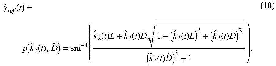
[0093] With reference to FIG. 14, the controller 38 is shown including the curvature input scaling module 200. The curvature input scaling module 200 is in communication with an estimator 202 configured to generate the estimated trailer length {circumflex over (D)} and an estimated hitch angle {circumflex over (.gamma.)}(t) based on a vehicle yaw rate .omega..sub.1(t) and a trailer yaw rate .omega..sub.2(t). As described herein, the vehicle and trailer yaw rates .omega..sub.1(t), .omega..sub.2(t) may be provided to the controller 38 via vehicle yaw rate sensor 52 and trailer yaw rate sensor 54, respectively. The estimator 202 provides the estimated trailer length {circumflex over (D)} to the curvature input scaling module 200 to enable the curvature input {circumflex over (k)}.sub.2(t) to be computed as described previously herein with reference to FIG. 13. The estimator 202 also provides the estimated trailer length {circumflex over (D)} to a curvature mapping module 204 of the controller 38, which is denoted by p({circumflex over (k)}.sub.2(t), {circumflex over (D)}) for the purposes of simplicity. The curvature mapping module 204 is configured to generate a reference hitch angle {circumflex over (.gamma.)}.sub.ref(t) based on the estimated trailer length D received from the estimator 202 and the curvature input {circumflex over (k)}.sub.2(t) received from the curvature input scaling module 200. The reference hitch angle {circumflex over (.gamma.)}.sub.ref(t) corresponds to a steady-state hitch angle needed to achieve the curvature input {circumflex over (k)}.sub.2(t) and is provided by the following equation:
.gamma. ^ ref ( t ) = p ( k ^ 2 ( t ) , D ^ ) = sin - 1 ( k ^ 2 ( t ) L + k ^ 2 ( t ) D ^ 1 - ( k ^ 2 ( t ) L ) 2 + ( k ^ 2 ( t ) D ^ ) 2 ( k ^ 2 ( t ) D ^ ) 2 + 1 ) , ( 10 ) ##EQU00006##
where: {circumflex over (k)}.sub.2(t) is the curvature input, L is the drawbar length, and {circumflex over (D)} is the estimated trailer length.
[0094] The reference hitch angle {circumflex over (.gamma.)}.sub.ref(t), as provided by the curvature mapping module 204, and the estimated hitch angle {circumflex over (.gamma.)}(t), as provided by the estimator 202, are received by a subtractor 206 configured to generate a signal e(t) defined by the reference hitch angle {circumflex over (.gamma.)}.sub.ref(t) less the estimated hitch angle {circumflex over (.gamma.)}(t). The estimated hitch angle {circumflex over (.gamma.)}(t) is provided by the following equation:
.gamma. ^ ( t ) = sin - 1 .omega. 2 ( t ) D ^ v 2 ( t ) + .omega. 1 2 ( t ) L 2 + tan - 1 .omega. 1 ( t ) L v ( t ) , ( 11 ) ##EQU00007##
where: .omega..sub.1(t) is the vehicle yaw rate, .omega..sub.2(t) is the trailer yaw rate, L is the drawbar length, {circumflex over (D)} is the estimated trailer length, and .nu.(t) is vehicle speed. In real-time implementation, a Kalman filter may be used with the estimated hitch angle {circumflex over (.gamma.)}(t) along with an internal state measurement thereof.
[0095] The signal e(t) is provided to a proportional-integral (PI) controller 208 to generate a control variable u(t) defined by the following equation:
u(t)=K.sub.pe(t)+K.sub.i.intg..sub.0.sup.te(.tau.)d.tau., (12)
where: e(t) is the signal generated by the subtractor 206, K.sub.p is a proportional coefficient having a non-negative value, and K.sub.i is an integral coefficient having a non-negative value.
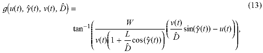
[0096] The control variable u(t) is provided to a hitch angle controller 210 along with the estimated trailer length {circumflex over (D)} and the estimated hitch angle {circumflex over (.gamma.)}(t), as provided by the estimator 202, and a vehicle speed .upsilon.(t), as provided by speed sensor 50 (FIG. 2), to generate a steering command in the form of a steering angle .delta.(t) supplied to the power assist steering system 57 (FIG. 2). The hitch angle controller 210 is denoted by g(u(t), {circumflex over (.gamma.)}(t), .upsilon.(t), {circumflex over (D)}) for purposes of simplicity and is provided by the following equation:
( u ( t ) , .gamma. ^ ( t ) , v ( t ) , D ^ ) = tan - 1 ( W v ( t ) ( 1 + L D ^ cos ( .gamma. ^ ( t ) ) ) ( v ( t ) D ^ sin ( .gamma. ^ ( t ) ) - u ( t ) ) ) , ( 13 ) ##EQU00008##
where: u(t) is the control variable generated by the PI controller 208, {circumflex over (D)} is the estimated trailer length, {circumflex over (.gamma.)}(t) is the estimated hitch angle provided by the estimator 202, W is the vehicle wheelbase, {circumflex over (D)} is the estimated trailer length, and .upsilon.(t) is the vehicle speed as provided by speed sensor 50 (FIG. 2).
[0097] When the controller 38 is configured according to the embodiment shown in FIG. 14, the trailer 14 arrives at the same equilibrium under steady state conditions (e.g., under a zero, maximum, or minimum curvature command k(t)) regardless of what estimated trailer length {circumflex over (D)} is used. For purposes of illustration and understanding, FIG. 15 illustrates a family of closed-loop equilibria .gamma..sub.eq(in degrees) as a function of the curvature command k(t) for estimated trailer lengths {circumflex over (D)}.di-elect cons.{1.5, 2, 2.5, . . . , 8}. For exemplary purposes, the equilibria .gamma..sub.eq correspond to the case where W=3.98 m, L=1.35 m, .delta..sub.max.sup.b=21.degree., .upsilon.(t)=5, K.sub.p=0.75. For purposes of simplicity, it is assumed that the integral control is turned off, that is, K.sub.i=0. As shown in FIG. 15, dashed line 212 corresponds to {circumflex over (D)}=1.5 m and dashed line 214 corresponds to {circumflex over (D)}=8 m. Notably, the estimated trailer lengths {circumflex over (D)}.di-elect cons.{1.5, 2, 2.5, . . . , 8} converge to the same equilibria .gamma..sub.eq at a zero curvature command k(t)=0, a maximum curvature command k(t)=1, and a minimum curvature command k(t)=-1. Thus, under certain conditions (e.g., steady-state conditions), the generated steering angle .delta.(t) is invariant to the estimated trailer length {circumflex over (D)}. In some embodiments, the transient response of the controller 38 may also be invariant to the estimated trailer length {circumflex over (D)}. This is accomplished by gain scheduling the proportional coefficient K.sub.p based only on the estimated trailer length {circumflex over (D)}. For example, the proportional coefficient K.sub.p may be defined by the function
1 .14 D ^ + .57 . ##EQU00009##
In this manner, the closed-loop dynamics are shaped in a uniform manner.
[0098] It is to be understood that variations and modifications can be made on the aforementioned structures and methods without departing from the concepts of the present invention, and further it is to be understood that such concepts are intended to be covered by the following claims unless these claims by their language expressly state otherwise.
* * * * *
D00000
D00001
D00002
D00003
D00004
D00005
D00006
D00007
D00008
D00009
D00010
D00011


XML
uspto.report is an independent third-party trademark research tool that is not affiliated, endorsed, or sponsored by the United States Patent and Trademark Office (USPTO) or any other governmental organization. The information provided by uspto.report is based on publicly available data at the time of writing and is intended for informational purposes only.
While we strive to provide accurate and up-to-date information, we do not guarantee the accuracy, completeness, reliability, or suitability of the information displayed on this site. The use of this site is at your own risk. Any reliance you place on such information is therefore strictly at your own risk.
All official trademark data, including owner information, should be verified by visiting the official USPTO website at www.uspto.gov. This site is not intended to replace professional legal advice and should not be used as a substitute for consulting with a legal professional who is knowledgeable about trademark law.