Automatic Control Method For Battling Device, Battling Device, And Readable Storage Medium
LU; Sixi ; et al.
U.S. patent application number 16/179766 was filed with the patent office on 2019-03-07 for automatic control method for battling device, battling device, and readable storage medium. The applicant listed for this patent is Tencent Technology (Shenzhen) Company Limited. Invention is credited to Yao Chen, Chuankang Fan, Chao Gong, Qingwei He, Yanqing Jing, Lujie Kang, Sixi LU, Ming Zhao, Zhe Zhu.
| Application Number | 20190070518 16/179766 |
| Document ID | / |
| Family ID | 56631291 |
| Filed Date | 2019-03-07 |


| United States Patent Application | 20190070518 |
| Kind Code | A1 |
| LU; Sixi ; et al. | March 7, 2019 |
AUTOMATIC CONTROL METHOD FOR BATTLING DEVICE, BATTLING DEVICE, AND READABLE STORAGE MEDIUM
Abstract
A first battling device has one or more processors, memory, one or more wireless receiving components; and one or more driving component for moving the first battling device. The first battling device receives a radio signal by using at least one of the wireless receiving components, the radio signal being broadcast by a wireless transmitting component of a second battling device that is distinct from the first battling device. The first battling device determines a position of the first battling device relative to the second battling device according to respective position information of the at least one of the wireless receiving components of the first battling device that have received the radio signal. The first battling device performs a predetermined action according to the respective position information of the at least one of the wireless receiving components of the first battling device that have received the radio signal.
| Inventors: | LU; Sixi; (Shenzhen, CN) ; Fan; Chuankang; (Shenzhen, CN) ; Kang; Lujie; (Shenzhen, CN) ; Zhao; Ming; (Shenzhen, CN) ; He; Qingwei; (Shenzhen, CN) ; Gong; Chao; (Shenzhen, CN) ; Jing; Yanqing; (Shenzhen, CN) ; Zhu; Zhe; (Shenzhen, CN) ; Chen; Yao; (Shenzhen, CN) | ||||||||||
| Applicant: |
|
||||||||||
|---|---|---|---|---|---|---|---|---|---|---|---|
| Family ID: | 56631291 | ||||||||||
| Appl. No.: | 16/179766 | ||||||||||
| Filed: | November 2, 2018 |
Related U.S. Patent Documents
| Application Number | Filing Date | Patent Number | ||
|---|---|---|---|---|
| PCT/CN2017/083155 | May 5, 2017 | |||
| 16179766 | ||||
| Current U.S. Class: | 1/1 |
| Current CPC Class: | A63H 17/045 20130101; A63H 17/36 20130101; A63H 17/28 20130101; A63H 17/006 20130101; A63H 30/04 20130101; A63H 17/00 20130101 |
| International Class: | A63H 30/04 20060101 A63H030/04; A63H 17/045 20060101 A63H017/045; A63H 17/28 20060101 A63H017/28; A63H 17/36 20060101 A63H017/36 |
Foreign Application Data
| Date | Code | Application Number |
|---|---|---|
| May 6, 2016 | CN | 201610296902.3 |
Claims
1. A method for automatically controlling a battling device, at a first battling device having one or more processors, memory, one or more wireless receiving components; and one or more driving component for moving the first battling device: receiving a radio signal by using at least one of the wireless receiving components, the radio signal being broadcast by a wireless transmitting component of a second battling device that is distinct from the first battling device; determining a position of the first battling device relative to the second battling device according to respective position information of the at least one of the wireless receiving components of the first battling device that have received the radio signal; and performing a predetermined action according to the respective position information of the at least one of the wireless receiving components of the first battling device that have received the radio signal.
2. The method according to claim 1, wherein: a first wireless receiving component is disposed at a front end of the first battling device, and the first wireless receiving component is configured to receive a radio signal from the front of the first battling device; a second wireless receiving component is disposed at a rear end of the first battling device, and the second wireless receiving component is configured to receive a radio signal from the rear of the first battling device; a third wireless receiving component is disposed on a left side of the first battling device, and the third wireless receiving component is configured to receive a radio signal from the left side of the first battling device; and a fourth wireless receiving component is disposed on a right side of the first battling device, and the fourth wireless receiving component is configured to receive a radio signal from the right side of the battling device.
3. The method according to claim 2, wherein the determining a position of the first battling device relative to the second battling device according to respective position information of the at least one of the wireless receiving components of the first battling device that have received the radio signal comprises: determining that the second battling device is located at the left front of the first battling device when both the first wireless receiving component and the third wireless receiving component receive a radio signal; determining that the second battling device is located at the right front of the first battling device when both the first wireless receiving component and the fourth wireless receiving component receive a radio signal; determining that the second battling device is located at the left rear of the first battling device when both the second wireless receiving component and the third wireless receiving component receive a radio signal; and determining that the second battling device is located at the right rear of the first battling device when both the second wireless receiving component and the fourth wireless receiving component receive a radio signal.
4. The method according to claim 1, including: before determining the position of the first battling device relative to the second battling device according to the respective position information of the at least one of the wireless receiving components of the first battling device that have received the radio signal: obtaining a device identifier comprised in the radio signal, and determining the radio signal as a valid signal when a data format of the radio signal satisfies a predetermined data format, the predetermined data format being a data format that are pre-established between the battling devices.
5. The method according to claim 1, wherein performing the predetermined action according to the relative position comprises: controlling, by using a driving component according to the respective position information, the first battling device relative to a position of the second battling device in a respective direction.
6. The method according to claim 1, wherein performing the predetermined action according to the relative position comprises: transmitting a radio attack signal to the position of the second battling device by using a wireless transmitting component according to the respective position information, the radio attack signal comprising an attack parameter.
7. The method according to claim 1, including: after the determining the position of the first battling device relative to the second battling device according to the position information of the wireless receiving component receiving the radio signal: sending the relative position to a control device; receiving a control instruction delivered by the control device, the control instruction being generated by the control device according to the relative position; and performing a corresponding action according to the control instruction.
8. A first battling device, comprising: one or more processors; memory; one or more wireless receiving components; one or more driving component for moving the first battling device; and a plurality of instructions stored in the memory that, when executed by the one or more processors, cause the one or more processors to perform the following operations: receiving a radio signal by using at least one of the wireless receiving components, the radio signal being broadcast by a wireless transmitting component of a second battling device that is distinct from the first battling device; determining a position of the first battling device relative to the second battling device according to respective position information of the at least one of the wireless receiving components of the first battling device that have received the radio signal; and performing a predetermined action according to the respective position information of the at least one of the wireless receiving components of the first battling device that have received the radio signal.
9. The first battling device according to claim 8, wherein: a first wireless receiving component is disposed at a front end of the first battling device, and the first wireless receiving component is configured to receive a radio signal from the front of the first battling device; a second wireless receiving component is disposed at a rear end of the first battling device, and the second wireless receiving component is configured to receive a radio signal from the rear of the first battling device; a third wireless receiving component is disposed on a left side of the first battling device, and the third wireless receiving component is configured to receive a radio signal from the left side of the first battling device; and a fourth wireless receiving component is disposed on a right side of the first battling device, and the fourth wireless receiving component is configured to receive a radio signal from the right side of the battling device.
10. The first battling device according to claim 9, wherein the determining a position of the first battling device relative to the second battling device according to respective position information of the at least one of the wireless receiving components of the first battling device that have received the radio signal comprises: determining that the second battling device is located at the left front of the first battling device when both the first wireless receiving component and the third wireless receiving component receive a radio signal; determining that the second battling device is located at the right front of the first battling device when both the first wireless receiving component and the fourth wireless receiving component receive a radio signal; determining that the second battling device is located at the left rear of the first battling device when both the second wireless receiving component and the third wireless receiving component receive a radio signal; and determining that the second battling device is located at the right rear of the first battling device when both the second wireless receiving component and the fourth wireless receiving component receive a radio signal.
11. The first battling device according to claim 8, wherein the operations include: before determining the position of the first battling device relative to the second battling device according to the respective position information of the at least one of the wireless receiving components of the first battling device that have received the radio signal: obtaining a device identifier comprised in the radio signal, and determining the radio signal as a valid signal when a data format of the radio signal satisfies a predetermined data format, the predetermined data format being a data format that are pre-established between the battling devices.
12. The first battling device according to claim 8, wherein performing the predetermined action according to the relative position comprises: controlling, by using a driving component according to the respective position information, the first battling device relative to a position of the second battling device in a respective direction.
13. The first battling device according to claim 8, wherein performing the predetermined action according to the relative position comprises: transmitting a radio attack signal to the position of the second battling device by using a wireless transmitting component according to the respective position information, the radio attack signal comprising an attack parameter.
14. The first battling device according to claim 8, wherein the operations include: after the determining the position of the first battling device relative to the second battling device according to the position information of the wireless receiving component receiving the radio signal: sending the relative position to a control device; receiving a control instruction delivered by the control device, the control instruction being generated by the control device according to the relative position; and performing a corresponding action according to the control instruction.
15. A non-transitory computer-readable storage medium storing a plurality of instructions configured for execution by a first battling device having one or more processors, one or more wireless receiving components and one or more driving component for moving the first battling device, wherein the plurality of instructions cause the first battling device to perform the following operations: receiving a radio signal by using at least one of the wireless receiving components, the radio signal being broadcast by a wireless transmitting component of a second battling device that is distinct from the first battling device; determining a position of the first battling device relative to the second battling device according to respective position information of the at least one of the wireless receiving components of the first battling device that have received the radio signal; and performing a predetermined action according to the respective position information of the at least one of the wireless receiving components of the first battling device that have received the radio signal.
16. The non-transitory computer-readable storage medium according to claim 15, wherein: a first wireless receiving component is disposed at a front end of the first battling device, and the first wireless receiving component is configured to receive a radio signal from the front of the first battling device; a second wireless receiving component is disposed at a rear end of the first battling device, and the second wireless receiving component is configured to receive a radio signal from the rear of the first battling device; a third wireless receiving component is disposed on a left side of the first battling device, and the third wireless receiving component is configured to receive a radio signal from the left side of the first battling device; and a fourth wireless receiving component is disposed on a right side of the first battling device, and the fourth wireless receiving component is configured to receive a radio signal from the right side of the battling device.
17. The non-transitory computer-readable storage medium according to claim 16, wherein the determining a position of the first battling device relative to the second battling device according to respective position information of the at least one of the wireless receiving components of the first battling device that have received the radio signal comprises: determining that the second battling device is located at the left front of the first battling device when both the first wireless receiving component and the third wireless receiving component receive a radio signal; determining that the second battling device is located at the right front of the first battling device when both the first wireless receiving component and the fourth wireless receiving component receive a radio signal; determining that the second battling device is located at the left rear of the first battling device when both the second wireless receiving component and the third wireless receiving component receive a radio signal; and determining that the second battling device is located at the right rear of the first battling device when both the second wireless receiving component and the fourth wireless receiving component receive a radio signal.
18. The non-transitory computer-readable storage medium according to claim 15, wherein the operations include: before determining the position of the first battling device relative to the second battling device according to the respective position information of the at least one of the wireless receiving components of the first battling device that have received the radio signal: obtaining a device identifier comprised in the radio signal, and determining the radio signal as a valid signal when a data format of the radio signal satisfies a predetermined data format, the predetermined data format being a data format that are pre-established between the battling devices.
19. The non-transitory computer-readable storage medium according to claim 15, wherein performing the predetermined action according to the relative position comprises: controlling, by using a driving component according to the respective position information, the first battling device relative to a position of the second battling device in a respective direction.
20. The non-transitory computer-readable storage medium according to claim 15, wherein performing the predetermined action according to the relative position comprises: transmitting a radio attack signal to the position of the second battling device by using a wireless transmitting component according to the respective position information, the radio attack signal comprising an attack parameter.
Description
PRIORITY CLAIMS AND RELATED APPLICATIONS
[0001] This application is a continuation-in-part application of PCT application number: PCT/CN2017/083155, entitled "AUTOMATIC CONTROL SYSTEM AND METHOD FOR BATTLING DEVICE, AND BATTLING DEVICE", filed with the Chinese Patent Office on May 5, 2017, which claims priority to Chinese Patent Application No. 201610296902.3, entitled "AUTOMATIC CONTROL SYSTEM AND METHOD FOR BATTLING DEVICE, AND BATTLING DEVICE" filed with the Patent Office of China on May 6, 2016, all of which are incorporated by reference in their entirety.
FIELD OF THE TECHNOLOGY
[0002] This application relates to the field of signal transmission, and in particular, to an automatic control method for a battling device, a battling device, and a readable storage medium.
BACKGROUND OF THE DISCLOSURE
[0003] With the development of remote control technology, special radio controls can be used for controlling a battling device to battle. The battling device may be a smart battling toy car, a smart battling toy airplane, or the like. During battling between battling devices, players may use radio controls to control the respective battling devices and instruct and battling devices to move or initiate an attack. For example, the player may press a designated key on the remote control to instruct the remote control to send an attack instruction to the corresponding battling device. After receiving the attack instruction, the battling device transmits an infrared ray to simulate an attack. After receiving the infrared ray, the other battling device automatically simulate a state under an attack, and perform actions such as overturn or stop.
SUMMARY
[0004] Conventionally, the battling devices can battle only under the control of players, and when the number of players is less than two (there is only one player), battling cannot be performed, even if the player has two battling devices, between the two battling devices since the player can only manually control one battling device. Or, battling cannot be performed between the battling devices either when the battling devices are not controlled by the player.
[0005] On the basis of the foregoing technical problem, the embodiments of this application provide an automatic control system for a battling device having a position sensing function and an automatic control function. One player may implement an effect of battling with a virtual player by using the battling system, thereby breaking through the restriction that one player cannot perform battling, and improving the interest of battling by using a battling device.
[0006] In one aspect, a method is performed at a first battling device having one or more processors, memory, one or more wireless receiving components; and one or more driving component for moving the first battling device. The first battling device receives a radio signal by using at least one of the wireless receiving components, the radio signal being broadcast by a wireless transmitting component of a second battling device that is distinct from the first battling device. The first battling device determines a position of the first battling device relative to the second battling device according to respective position information of the at least one of the wireless receiving components of the first battling device that have received the radio signal. The first battling device performs a predetermined action according to the respective position information of the at least one of the wireless receiving components of the first battling device that have received the radio signal.
[0007] According to a second aspect of the present disclosure, a computing device includes one or more processors, memory, a display, a touch-sensitive surface, and a plurality of instructions stored in the memory that, when executed by the one or more processors, cause the computing device to perform the aforementioned method.
[0008] According to a third aspect of the present disclosure, a non-transitory computer readable storage medium storing a plurality of instructions configured for execution by a computing device having one or more processors, the plurality of instructions causing the computing device to perform the aforementioned method.
[0009] Details of one or more embodiments of the present disclosure are provided in the following accompanying drawings and descriptions. Other features, objectives, and advantages of the present disclosure become clear in the specification, the accompanying drawings, and the claims.
BRIEF DESCRIPTION OF THE DRAWINGS
[0010] To describe the technical solutions in the embodiments of this application more clearly, the following briefly describes the accompanying drawings required for describing the embodiments. Apparently, the accompanying drawings in the following description show merely some embodiments of this application, and a person of ordinary skill in the art may still derive other drawings from these accompanying drawings without creative efforts.
[0011] FIG. 1 is a schematic structural diagram of an automatic control system for a battling device according to an embodiment of this application;
[0012] FIG. 2A is a flowchart of an automatic control method for a battling device according to an embodiment of this application;
[0013] FIG. 2B and FIG. 2C are schematic diagrams of a disposing orientation of a wireless receiving component in a first battling device;
[0014] FIG. 2D is a flowchart of a process of determining, by a first battling device, a relative position with a second battling device;
[0015] FIG. 2E is a flowchart of an automatic control method for a battling device according to another embodiment of this application;
[0016] FIG. 2F is a flowchart of an automatic control method for a battling device according to still another embodiment of this application;
[0017] FIG. 2G is a flowchart of an automatic control method for a battling device according to still another embodiment of this application;
[0018] FIG. 3A is a flowchart of an operating process of an automatic control system for a battling device according to an embodiment of this application;
[0019] FIG. 3B is a schematic implementation diagram of the embodiment shown in FIG. 3A;
[0020] FIG. 4A is a schematic structural diagram of a battling device according to an embodiment of this application;
[0021] FIG. 4B is a schematic structural diagram of a battling device according to another embodiment of this application;
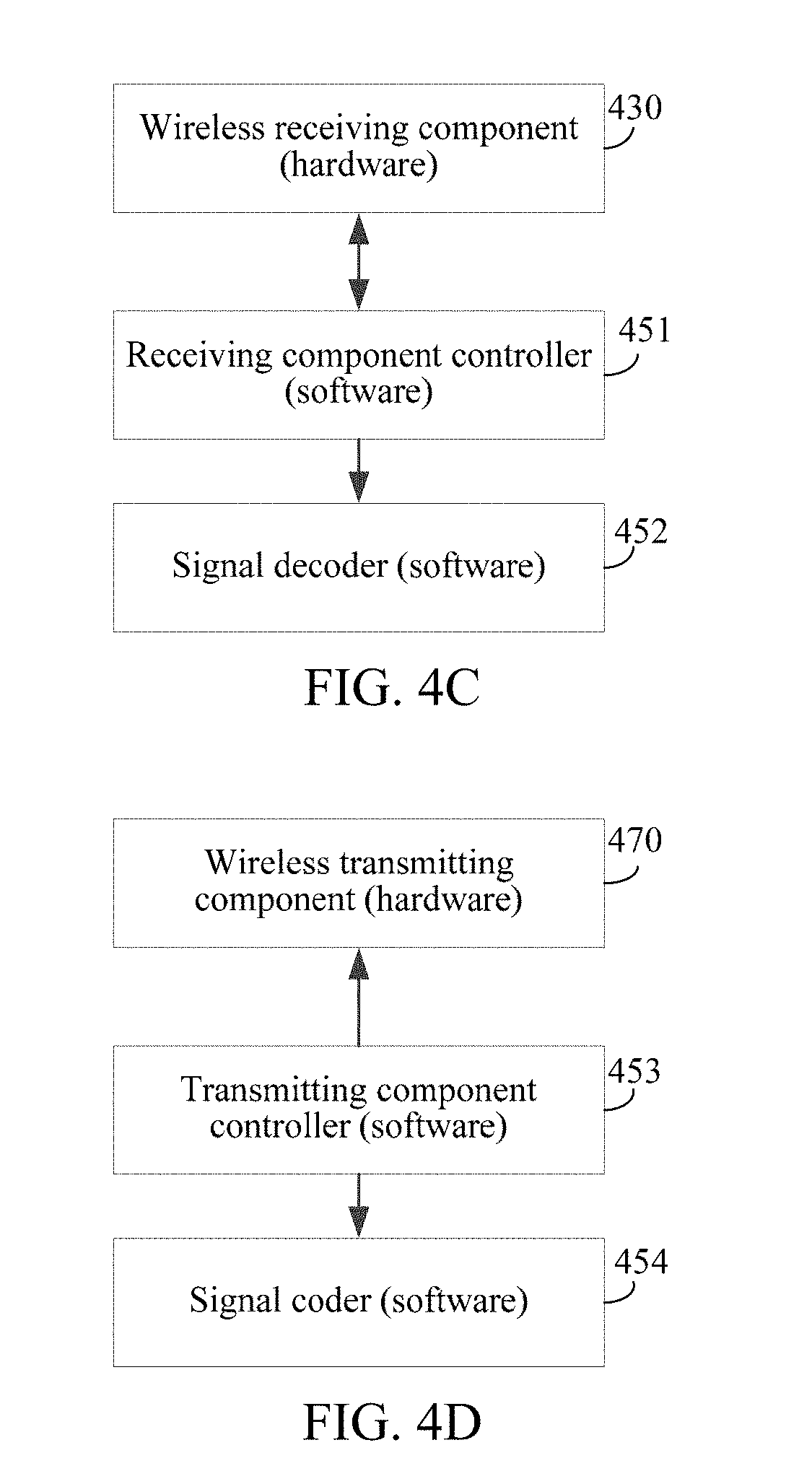
[0022] FIG. 4C is a schematic diagram of the process for receiving a radio signal by the battling device shown in FIG. 4A and FIG. 4B; and
[0023] FIG. 4D is a schematic diagram of the process for transmitting a radio signal by the battling device shown in FIG. 4A and FIG. 4B.
DESCRIPTION OF EMBODIMENTS
[0024] To make the objectives, technical solutions, and advantages of this application clearer, the following further describes the implementations of this application in detail with reference to the accompanying drawings.
[0025] To facilitate understanding, the following explains terms involved in the embodiments of this application. Battle: refer to a competition behavior between at least two devices; and battling between devices may include combat battling and non-combat battling. Devices that perform combat battling may attack each other, and the attack modes include but are not limited to physical attack (for example, transmitting an entity attack prop) and simulated attack (for example, transmitting a simulated attack signal). Devices that perform non-combat battling cannot initiate an attack. For example, the non-combat battling may refer to a racing behavior between the devices. When multiple players perform battling by controlling respective battling devices by means of control devices, the control devices send control instructions to the corresponding battling devices according to received control signals, to instruct the battling devices to execute corresponding actions, so as to implement a multiple battling effect between multiple battling devices.
[0026] In some embodiments, the battling devices can battle only under the control of players, and when the number of players is less than two (there is only one player), battling cannot be performed, even if the player has two battling devices, between the two battling devices since the player can only manually control one battling device. Or, battling cannot be performed between the battling devices either when the battling devices are not controlled by the player.
[0027] On the basis of the foregoing technical problem, the embodiments of this application provide an automatic control system for a battling device having a position sensing function and an automatic control function. One player may implement an effect of battling with a virtual player by using the battling system, thereby breaking through the restriction that one player cannot perform battling, and improving the interest of battling by using a battling device.
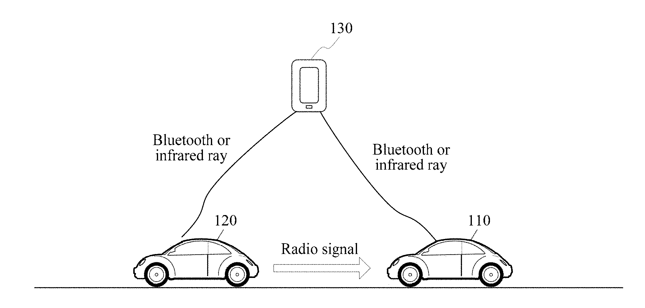
[0028] Referring to FIG. 1, FIG. 1 is a schematic structural diagram of an automatic control system for a battling device according to an embodiment of this application. The automatic control system for a battling device includes a first battling device 110, a second battling device 120, and a control device 130 configured to control the second battling device. The first battling device 110 is a battling device in an automatic control state. Specifically, the first battling device 110 may implement automatic control by means of an inbuilt control chip. The first battling device 110 may be a smart battling toy car, a smart battling toy airplane, or the like. Meanwhile, at least one wireless receiving component is disposed on a peripheral side of the first battling device 110. The at least one wireless receiving component has a respective corresponding receiving direction (e.g., with preferential receiving sensitivity in that direction relative to other directions), and is configured to receive a radio signal from the respective receiving direction. The first battling device 110 senses, according to the radio signal received by the wireless receiving component, a position of a signal source that transmits the radio signal. A wireless transmitting component is further disposed in the first battling device 110, and is configured to transmit an attack signal to another battling device in a battling process, to achieve an effect of simulating an attack.
[0029] The second battling device 120 may be a smart battling toy car, a smart battling toy airplane, or the like. A wireless transmitting component is disposed in the second battling device 120. The wireless transmitting component is configured to broadcast a radio signal. Correspondingly, the first battling device 110 that battles with the second battling device 120 senses a relative position with the second battling device 120 after receiving the radio signal. In some embodiments, the second battling device 120 may be a battling device controlled by the control device 130. The control device 130 may be a wireless remote control or an electronic device of smart phones, and the second battling device 120 may be connected to the control device 130 by means of Bluetooth or infrared rays.
[0030] It should be noted that the second battling device 120 may be implemented as the first battling device 110 by means of an additionally added automatic control module; or both the first battling device 110 and the second battling device 120 are battling devices in each of which an automatic control module is configured, and the battling device becomes the first battling device 110 when enabling the automatic control function and becomes the second battling device 120 when not enabling the automatic control function. In some embodiments, the control device sends a role switching instruction to one or both of the battling devices, to switch the battling device from the manual control mode to the automatic control mode, and vice versa. In response to receiving the role switching instruction, the receiving battle device switches its movement behavior, e.g., from following control instructions from the control device and sending wireless signals to surrounding battle devices, to detecting wireless signals from nearby battle devices, and maneuver automatically based on position information deduced from the wireless signals and preset movement strategies.
[0031] In some embodiments, when a player performs battling by using the first battling device 110 and the second battling device 120, the first battling device 110 further needs to be connected to the control device 130, configured to receive battling data, such as attack data and state data indicating a current state, sent by the first battling device 110 and the second battling device 120.
[0032] It should be noted that, in this embodiment, description is provided by an example in which the automatic control system for a battling device includes one first battling device and one second battling device. In other possible implementation environments, the automatic control system for a battling device may include multiple first battling devices and multiple second battling devices. The number of first battling devices and the number of second battling devices in the automatic control system for a battling device are not limited in this application.
[0033] It should also be noted that, the second battling device 120 in FIG. 1 may be a battling device controlled by a player, that is, the player may manually control the second battling device 120 to battle with the first battling device 110; the second battling device 120 in FIG. 1 may also be a battling device in an automatic control state (similar to the first battling device 110), that is, a player may watch automatic battling between the first battling device 110 and the second battling device 120; or the second battling device 120 in FIG. 1 may also be a fixed target, that is, a player may watch the first battling device 110 to automatically run towards the second battling device 120, or, watch the first battling device 110 to automatically initiate an attack towards the second battling device 120.
[0034] By using the automatic control system for a battling device provided in this application, by configuring a position sensing function and an automatic control function for the battling device to enable the battling device to determine, according to a radio signal broadcast by another battling device, a relative position with the another battling device, and to further implement automatic control of the battling device according to the relative position, the problem that due to the fact that all the battling devices can perform battling under the control of players, battling between the battling devices cannot be performed when the battling devices are not controlled by the players or the number of the players is less than two is resolved. The effect that one player may also implement battling between battling devices by adding a battling device having an automatic control function is achieved.
[0035] Referring to FIG. 2A, FIG. 2A is a flowchart of an automatic control method for a battling device according to an embodiment of this application. This embodiment describes by using the first battling device 110 in FIG. 1 as an example. The method may include the following steps.
[0036] Step 201: Receive a radio signal by using at least one wireless receiving component of the first battling device, the radio signal being broadcast by a wireless transmitting component of a second battling device.
[0037] When a player uses a first battling device in an automatic control state to battle with a second battling device controlled by a control device, the second battling device repeatedly broadcast a radio signal by means of an inbuilt wireless transmitting component. The radio signal carries a device identifier of the second battling device. The wireless transmitting component may be an infrared transmitting tube or a laser transmitting tube. Correspondingly, the radio signal is a modulated infrared signal or laser signal, which is not limited in this embodiment. In some embodiments, the radio signal is encoded with an identifier of an automatic control mode, and the identifier of the automatic control mode is optionally transmitted from the control device to the second battling device and encoded into the radio signal at the second battling device. The first battling device receives the radio signal and decodes the identifier to determine a respective automatic control mode to follow. For example, the different possible automatic control modes include evasive control mode, offensive control mode, attack control mode, energy preservation control mode, etc. The automatic control of the first battling device changes depending on the identifier of the automatic control mode that is detected in the radio signal. In this manner, during the automatic control of the first battling device, the user can still exert some control over the first battling device intermittently through the control device and the second battling device without full manual control of the first battling device, and increase the flexibility and control of the battle scenarios.
[0038] The first battling device participating in the battling may receive the radio signal by means of at least one wireless receiving component disposed on a peripheral side of the first battling device while the second battling device broadcasts the radio signal. The wireless receiving component has a respective receiving direction corresponding to the radio signal, and is configured to receive a radio signal from a designated direction. For example, one wireless receiving component is disposed at a front end of the first battling device, and is configured to receive a radio signal from the front. Still for example, two wireless receiving components are correspondingly disposed at a front end and a rear end of the first battling device, and are respectively configured to receive radio signals from the front and the rear.
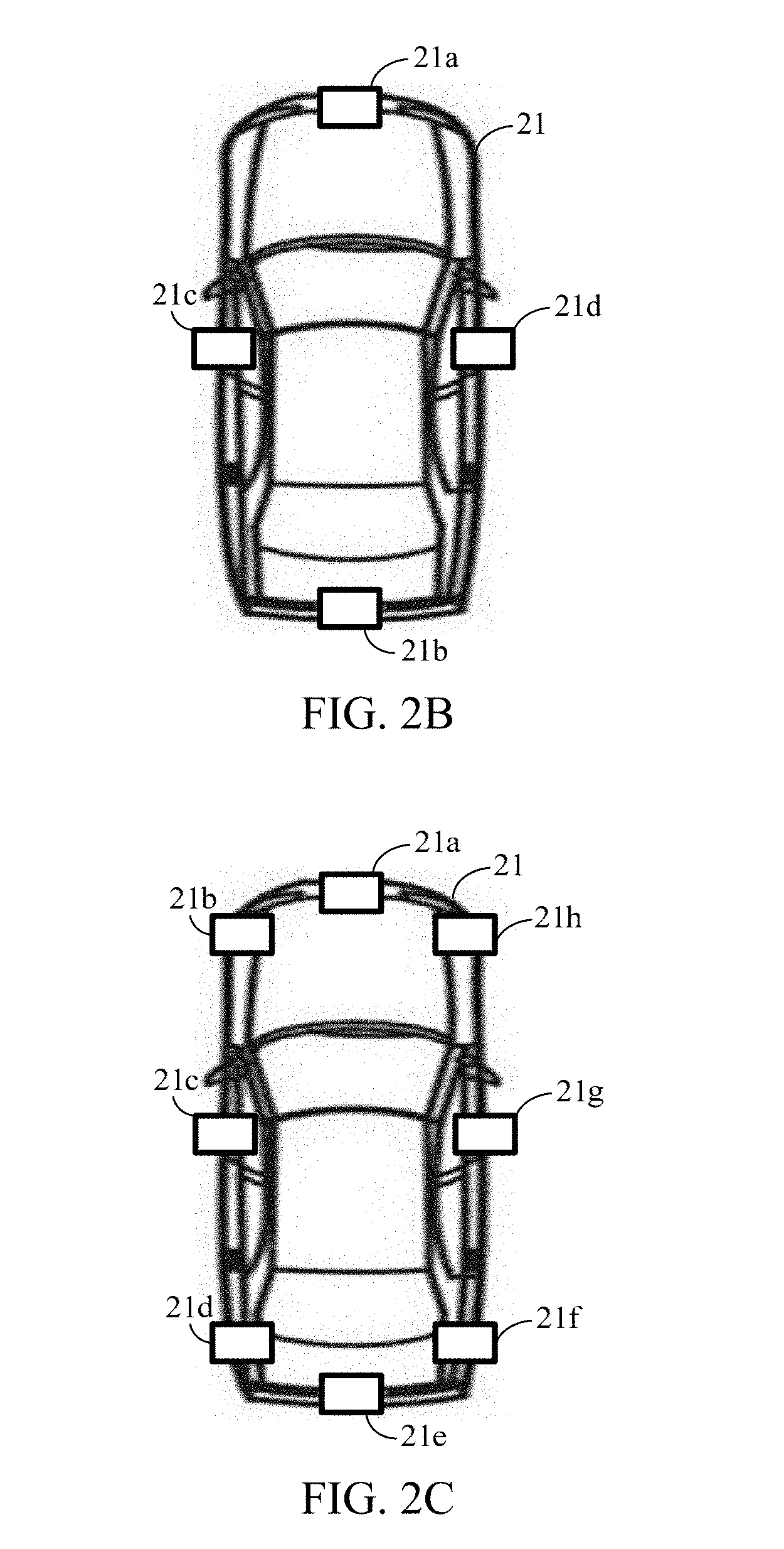
[0039] In a possible implementation, as shown in FIG. 2B, four wireless receiving components are symmetrically disposed on a peripheral side of a first battling device 21, respectively, a first wireless receiving component 21a, a second wireless receiving component 21b, a third wireless receiving component 21c, and a fourth wireless receiving component 21d, and the four wireless receiving components are respectively configured to receive radio signals from the front, the rear, the left side, and the right side.
[0040] To further improve the precision of sensing the position of the second battling device by the first battling device, as shown in FIG. 2C, in another possible implementation, eight wireless receiving components are disposed on the peripheral sides of a first battling device 21, respectively, a first wireless receiving component 21a, a second wireless receiving component 21b, a third wireless receiving component 21c, a fourth wireless receiving component 21d, a fifth wireless receiving component 21e, a sixth wireless receiving component 21f, a seventh wireless receiving component 21g, and an eighth wireless receiving component 21h, and the eight wireless receiving components are respectively configured to receive radio signals from the front, the left front, the left side, the left rear, the rear, the right rear, the right side, and the right front.
[0041] It should be noted that, in other possible implementations, more than eight wireless receiving components may be disposed on the peripheral side of the first battling device. This embodiment does not limit the specific number and disposing orientations of the wireless receiving components disposed on the peripheral side of the first battling device. In some embodiments, the first battling device includes motor controlled wireless receiving components that move automatically relative to a respective fixed anchor location to seek the radio signals send out by the second battling device. In some embodiments, the first battling device automatically adjusts the calculation of the location of the second battling device by taking into the changes in the locations of the various wireless receiving components and the changes in strengths of the radio signals detected by the different wireless receiving components as a result of the changed positions of the wireless receiving components. In some embodiments, because the radio signal strength and location change rapidly when the second battling device is in motion. The first battling device prohibits movement of the wireless sensing components when the first battling device is in motion, and when the received radio signal is changing in position and magnitude by more than a threshold amount within a threshold amount of time.
[0042] Step 202: Determine a relative position with the second battling device according to position information of the wireless receiving component receiving the radio signal.
[0043] The wireless receiving components in the first battling device each has a respective receiving direction and is not able to receive a radio signal from a direction apart from the respective receiving direction. For example, the wireless receiving component with the receiving direction being the front is not able to receive a radio signal from the rear. Therefore, the radio signal broadcast by the second battling device can be received by only some wireless receiving components, and the first battling device may further determine, according to position information of the wireless receiving components receiving the radio signal, a relative position between the second battling device transmitting the radio signal and the first battling device.
[0044] Step 203: Perform a predetermined action according to the relative position.
[0045] To achieve the effect of battling with the second battling device, after determining the relative position with the second battling device, the first battling device determines, according to a preset automatic control logic and the relative position, a predetermined action to be performed. The predetermined action performed by the first battling device controlled by the preset automatic control logic includes at least one of automatic following and automatic attacking. In some embodiments, the automatic control logic also includes repeating a detected motion pattern, or forming a predefined formation with the second battling device. In some embodiments, the control device is configured to send predefined identifiers for each of the control modes in accordance with user instruction (e.g., on a user interface of the control device) to the second battling device, and have the second battling device encodes the identifiers in the radio signal sent out to the first battling device, such that the first battling device decodes the radio signal, and automatically moves in accordance with the decoded automatic control mode and the motion of the second battling device (e.g., controlled by the user manually through the control device). The control logic for each of the automatic control mode is pre-stored on the first battling device, so that the communication bandwidth requirement on the first battling device is low.
[0046] In view of the above, by using the automatic control method for a battling device provided in this application, by configuring a position sensing function and an automatic control function for the battling device to enable the battling device to determine, according to a radio signal broadcast by another battling device, a relative position with the another battling device, and to further implement automatic control of the battling device according to the relative position, the problem that due to the fact that all the battling devices can perform battling under the control of players, battling between the battling devices cannot be performed when the battling devices are not controlled by the players or the number of the players is less than two is resolved. The effect that one player may also implement battling between battling devices by adding a battling device having an automatic control function is achieved.
[0047] In combination with FIG. 2B, the first battling device 21 includes four wireless receiving components, the first wireless receiving component 21a and the second wireless receiving component 21b are disposed opposite to each other, the third wireless receiving component 21c and the fourth wireless receiving component 21d are disposed opposite to each other, the first wireless receiving component 21a is configured to receive a radio signal from the front of the first battling device 21, the second wireless receiving component 21b is configured to receive a radio signal from the rear of the first battling device 21, the third wireless receiving component 21c is configured to receive a radio signal from the left side of the first battling device 21, and the fourth wireless receiving component 21d is configured to receive a radio signal from the right side of the first battling device 21. As shown in FIG. 2D, step 202 may include the following steps:
[0048] Step 202A: Determine that the second battling device is located at the front of the first battling device when the first wireless receiving component receives a radio signal.
[0049] Only the first wireless receiving component in the first battling device is configured to receive a radio signal from the front, and therefore when only the first wireless receiving component among the wireless components of the first battling device receives a radio signal, the first battling device determines that the second battling device is located at the front of the first battling device.
[0050] Step 202B: Determine that the second battling device is located at the rear of the first battling device when the second wireless receiving component receives a radio signal.
[0051] Similar to step 202A, only the second wireless receiving component in the first battling device is configured to receive a radio signal from the rear, and therefore when only the second wireless receiving component among the wireless components of the first battling device receives a radio signal, the first battling device determines that the second battling device is located at the rear of the first battling device.
[0052] Step 202C: Determine that the second battling device is located at a left side of the first battling device when the third wireless receiving component receives a radio signal.
[0053] Only the third wireless receiving component in the first battling device is configured to receive a radio signal from the left side, and therefore when only the third wireless receiving component among the wireless components of the first battling device receives a radio signal, the first battling device determines that the second battling device is located at the left side of the first battling device.
[0054] Step 202D: Determine that the second battling device is located at a right side of the first battling device when the fourth wireless receiving component receives a radio signal.
[0055] Similar to step 202C, only the fourth wireless receiving component in the first battling device is configured to receive a radio signal from the right side, and therefore when only the fourth wireless receiving component among the wireless components of the first battling device receives a radio signal, the first battling device determines that the second battling device is located at the right side of the first battling device.
[0056] In an actual application process, the second battling device may be located at an inclined direction of the first battling device, at which time the radio signal broadcast by the second battling device by means of the wireless transmitting component is simultaneously received by two wireless receiving components located at adjacent positions.
[0057] Step 202E: Determine that the second battling device is located at the left front of the first battling device when both the first wireless receiving component and the third wireless receiving component receive a radio signal.
[0058] In the first battling device, the first wireless receiving component is configured to receive a radio signal from the front and the third wireless receiving component is configured to receive a radio signal from the left side, and therefore when the first wireless receiving component and the third wireless receiving component simultaneously receive a radio signal, the first battling device determines that the second battling device is located at the left front of the first battling device.
[0059] Step 202F: Determine that the second battling device is located at the right front of the first battling device when both the first wireless receiving component and the fourth wireless receiving component receive a radio signal.
[0060] Similar to step 202E, in the first battling device, the first wireless receiving component is configured to receive a radio signal from the front and the fourth wireless receiving component is configured to receive a radio signal from the right side, and therefore when the first wireless receiving component and the fourth wireless receiving component simultaneously receive a radio signal, the first battling device determines that the second battling device is located at the right front of the first battling device.
[0061] Step 202G: Determine that the second battling device is located at the left rear of the first battling device when both the second wireless receiving component and the third wireless receiving component receive a radio signal.
[0062] Similar to step 202E, in the first battling device, the second wireless receiving component is configured to receive a radio signal from the rear and the third wireless receiving component is configured to receive a radio signal from the left side, and therefore when the second wireless receiving component and the third wireless receiving component simultaneously receive a radio signal, the first battling device determines that the second battling device is located at the left rear of the first battling device.
[0063] Step 202H: Determine that the second battling device is located at the right rear of the first battling device when both the second wireless receiving component and the fourth wireless receiving component receive a radio signal.
[0064] Similar to step 202E, in the first battling device, the second wireless receiving component is configured to receive a radio signal from the rear and the fourth wireless receiving component is configured to receive a radio signal from the right side, and therefore when the second wireless receiving component and the fourth wireless receiving component simultaneously receive a radio signal, the first battling device determines that the second battling device is located at the right rear of the first battling device.
[0065] By the steps, according to the position information of the wireless receiving components receiving a radio signal, the first battling device not only can determine a position of the second battling device relative to the first battling device in positive directions, but also can further precisely determine a position of the second battling device relative to the first battling device in inclined directions.
[0066] Step 202I: Perform control according to a preset seeking policy when at least three wireless receiving components receive a radio signal or none of the four wireless receiving components receives a radio signal, the preset seeking policy including at least one of random walk and rotating at a same place.
[0067] When at least three wireless receiving components, among the four wireless receiving components, receive a radio signal, the first battling device determines that a change in a moving track of the second battling device is relatively large and it is impossible to determine a relative position of the second battling device. Similarly, when none of the four wireless receiving components receives a radio signal, the first battling device determines that a distance with the second battling device is relatively long and it is impossible to determine a relative position of the second battling device.
[0068] When it is impossible to determine the relative position of the second battling device, the first battling device executes a preset seeking policy. In the process of executing the preset seeking policy, the first battling device may randomly walk or stay at a same place and rotate, and does not stop receiving a radio signal until the relative position of the second battling device can be determined according to the received radio signal. In some embodiments, the first battling device moves the wireless receiving components around their respective anchor positions to increase the chances of detecting the radio signals from the second battling device.
[0069] It should be noted that, in this embodiment, description is provided by an example in which the preset seeking policy includes at least one of random walk and rotating at a same place, which does not constitute a limitation to the present disclosure.
[0070] In this embodiment, by disposing multiple wireless receiving components on the peripheral side of the first battling device, the first battling device not only can determine a position of the second battling device relative to the first battling device in positive directions, but also can precisely determine a position of the second battling device relative to the first battling device in inclined directions according to position information of the wireless receiving components receiving a radio signal.
[0071] Schematically, as shown in FIG. 2E, step 203 may specifically include the following steps.
[0072] Step 203A: Control, by using a driving component according to the relative position, the first battling device to run towards a position of the second battling device.
[0073] When the first battling device controls, according to the preset automatic control logic, the first battling device to perform automatic following, the first battling device controls, by using the driving component, the first battling device to run towards the position of the second battling device.
[0074] For example, when the second battling device is located at the front of the first battling device, the first battling device controls, by using the driving component, the first battling device to move forward at an accelerated speed, to achieve an effect of following the second battling device.
[0075] Still for example, when the second battling device is located at the left front of the first battling device, the first battling device controls, by using the driving component, the first battling device to move towards the left front, to achieve an effect of following the second battling device.
[0076] It should be noted that when the first battling device runs towards the position of the second battling device according to the relative position, the first battling device is still able to receive a radio signal broadcast by the second battling device, and determine a real-time position of the second battling device according to the radio signal, so as to correct a running direction of the first battling device according to the real-time position (that is, circularly performing step 201 to step 203), and details are not described in the embodiments of this application again.
[0077] Step 203B: Transmit a radio attack signal to a position of the second battling device by using a wireless transmitting component according to the relative position, the radio attack signal including an attack parameter.
[0078] The first battling device not only can implement automatic following, but also can perform automatic attacking, to simulate an effect in which a player initiates an attack. Similar to disposing of the wireless transmitting component in the second battling device, a wireless transmitting component is also disposed in the first battling device.
[0079] In some embodiments, the wireless transmitting component may be an infrared transmitting tube or a laser transmitting tube having an omnidirectional transmitting capacity. When the preset automatic control logic instructs the first battling device to initiate an attack, the first battling device instructs the wireless transmitting component to omnidirectionally transmit an attack signal.
[0080] To implement oriented attack by the battling device, in another possible implementation, the wireless transmitting component may also be an infrared transmitting tube or a laser transmitting tube having a unidirectional transmitting capacity disposed on the peripheral side of the wireless receiving component. When the preset automatic control logic instructs the first battling device to initiate an attack, the first battling device instructs the wireless transmitting component corresponding to the relative position to transmit an attack signal. The attack signal carries information such as an identifier of the first battling device and an attack parameter. The attack parameter includes strength of a transmitted infrared ray and laser beam.
[0081] In this embodiment, the first battling device can implement an effect of simulating control by a player according to the preset automatic control logic, and not only can implement automatic following, but also can implement automatic attack, thereby increasing the interest and realness of the battling process.
[0082] When the first battling device receives a radio signal by using the wireless receiving component, the first battling device may probably receive a radio signal broadcast by a non-battling device. For example, the first battling device may probably receive an infrared signal sent by another remote control. To avoid interference by other radio signals and improve the stability of automatic control of the whole battling device, after step 201 shown in FIG. 2F, the method further includes the following steps.
[0083] Step 204: Obtain a device identifier included in the radio signal; check whether the device identifier is a device identifier of the second battling device; and determine that the radio signal is a valid signal if the device identifier is the device identifier of the second battling device.
[0084] The radio signal broadcast by the second battling device includes the device identifier of the second battling device, and the first battling device stores a device identifier of at least one second battling device that battles with the first battling device at the initiation stage. When receiving the radio signal, the first battling device obtains the device identifier included in the radio signal. If the device identifier is not obtained, or the obtained device identifier is not the device identifier of the second battling device, the first battling device determines that the radio signal is an invalid signal and discards the radio signal; and if the obtained device identifier is the device identifier of the second battling device, the first battling device determines that the radio signal is a valid signal, and step 202 is performed.
[0085] Step 205: Check whether a data format of the radio signal is consistent with a predetermined data format, the predetermined data format being a data format agreed between battling devices; and determine that the radio signal is a valid signal if the data format of the radio signal is consistent with the predetermined data format.
[0086] In another possible implementation, signal transmission is performed by using an agreed data format between battling devices that battle with each other. When receiving a radio signal, the first battling device checks whether the radio signal satisfies the agreed data format; if the radio signal satisfies the agreed data format, the first battling device determines that the radio signal is an invalid signal and discards the radio signal; and if the radio signal satisfies the agreed data format, the first battling device determines that the radio signal is a valid signal, and step 202 is performed.
[0087] For example, a signal header of a radio signal sent by the second battling device according to the data format agreed between battling devices includes a keyword "Position". After receiving the radio signal, the first battling device checks whether the signal header of the radio signal includes "Position"; if detecting that the signal header includes "Position", the first battling device determines that the radio signal is a valid signal; and if detecting that the signal header does not include "Position", the first battling device determines that the radio signal is an invalid signal and discards the radio signal.
[0088] In this embodiment, after receiving the radio signal, the first battling device checks whether the radio signal is a valid signal and discards the radio signal when determining that the radio signal is an invalid signal, thereby avoiding automatic control abnormity caused by erroneous processing of the radio signal, and improving the stability of the whole signal processing system.
[0089] In the foregoing embodiment, description is provided by an example in which the first battling device performs automatic control according to the preset automatic control logic of the first battling device. However, since the processing capacity of the first battling device control chip is restricted, the first battling device can only implement some simple actions. To enable the first battling device to implement enriched actions, as shown in FIG. 2G, step 203 may be replaced with the following steps.
[0090] Step 206: Send the relative position to a control device.
[0091] Before a player controls, by using a control device, the second battling device to battle with the first battling device, the player establishes, by using the control device, a persistent connection (for example, a Bluetooth connection) with the first battling device. In the battling process, the player only needs to control the second battling device by using the control device, and the first battling device sends a relative position of the second battling device to the control device through the persistent connection, so that the control device determines, according to the relative position, an action to be performed by the first battling device.
[0092] Step 207: Receive a control instruction delivered by the control device, the control instruction being generated by the control device according to the relative position.
[0093] The control device has a relatively strong calculation and processing capacity, and therefore after receiving the relative position sent by the first battling device, the control device can determine, according to a complicated automatic control logic, an action to be performed by the first battling device, and send a corresponding control instruction to the first battling device through the established persistent connection.
[0094] Correspondingly, the first battling device receives, through the connection, the control instruction delivered by the control device.
[0095] In a possible implementation, the control device is connected to the second battling device, and therefore the control device may obtain a current moving speed of the second battling device, determine a following speed of the first battling device according to the moving speed, and generate a corresponding control instruction, to enable the first battling device to closely follow the second battling device. In another possible implementation, the control device may obtain a current battling state (for example, a battling damage situation) of the second battling device, determine, according to the battling state, an attack strength of the attack initiated by the first battling device, and generate a corresponding control instruction.
[0096] Step 208: Perform a corresponding action according to the control instruction.
[0097] The processing capacity of the control device is relatively strong, and correspondingly, the sent control instruction may instruct the first battling device to perform diversified actions, thereby enriching the battling effect of the battling device.
[0098] In some embodiments, the control device controls the first battling device and the second battling device in different manners, e.g., manually controlling the motion of the second battling device, while using the first battling device to battle with the second battling device through automatic motion control. In some embodiments, the control device sends control instructions as instructed by the user to the first battling device intermittently, such as switching automatic control mode, or stopping action, etc., either directly through a connection between the control device and the first battling device, or indirectly through a connection between the control device and the second battling device and through the radio signal send out by the second battling device. In some embodiments, the control device has powerful processing logic, and receives the position information of the second battling device from the first battling device through the direct connection between the control device and the first battling device, and sends corresponding motion instructions to control the movement of the first battling device in accordance with the selected automatic control mode. The motion instructions are sent to the first battling device without active participation of the user, and thus frees the user from focusing on manually controlling the motion of the second battling device.
[0099] In combination with the automatic control method for a battling device shown in FIG. 2A to FIG. 2G, as shown in FIG. 3A, FIG. 3A is a flowchart of an operating process of an automatic control system for a battling device according to an embodiment of this application.
[0100] Step 301: A second battling device broadcasts a radio signal by using a wireless transmitting component.
[0101] Step 302: A first battling device receives the radio signal by using at least one wireless receiving component.
[0102] An implementation of this step is similar to that of step 201, and details are not described herein again.
[0103] Step 303: The first battling device checks whether the received radio signal is a valid signal.
[0104] Similar to step 204 or step 205, the first battling device checks the received radio signal; if the radio signal is a valid signal, step 304 is performed; and if the radio signal is an invalid signal, the first battling device discards the radio signal.
[0105] Step 304: The first battling device determines a relative position between the second battling device and the first battling device according to position information of the wireless receiving component receiving the radio signal when the received radio signal is a valid signal.
[0106] Similar to step 202A to step 202I, the first battling device determines a relative position between the second battling device and the first battling device according to position information of the wireless receiving component receiving the radio signal, and determines, according to the relative position, an action to be performed.
[0107] Step 305: The first battling device performs a predetermined action according to the relative position.
[0108] In a possible implementation, similar to step 203A and step 203B, the first battling device controls, according to the relative position, the first battling device to follow the second battling device, and/or, initiate an attack towards the second battling device.
[0109] Step 306: The first battling device sends the relative position to a control device.
[0110] Step 307: The control device generates a corresponding control instruction according to the relative position.
[0111] Step 308: The control device sends the control instruction to the first battling device.
[0112] Step 309: The first battling device receives the control instruction delivered by the control device.
[0113] Step 310: The first battling device performs a corresponding action according to the control instruction.
[0114] In another possible implementation, the first battling device sends the relative position to the control device by means of the calculation capacity of the control device, so that the control device determines an action to be performed by the first battling device.
[0115] In combination with FIG. 3A and FIG. 3B, the automatic control system for a battling device includes a first battling device 31 and a second battling device 32. In the battling process, the second battling device 32 moves under the control of the control device (not shown in the figure) and broadcasts a radio signal to the surroundings. At this time, the second battling device 32 is located at the left front of the first battling device 31, a wireless receiving component 31a and a wireless receiving component 31c in the first battling device 31 receives the radio signal broadcast by the second battling device 32. The wireless receiving component 31a is located at the front end of the first battling device 31 and the wireless receiving component 31c is located at the left side of the first battling device 31, and therefore the first battling device determines that a relative position of the second battling device 32 is the left front. After determining the relative position of the second battling device, the first battling device 31 controls, according to the relative position, the first battling device 31 to run towards the left front; or control a wireless transmitting component (not shown in the figure) in the first battling device 31 to transmit a radio attack signal 33 to the second battling device 32. Correspondingly, after receiving the radio attack signal 33, the second battling device 32 simulates an attacked action (for example, car rollover or rotating).
[0116] In combination with the automatic control method for a battling device shown in FIG. 2A to FIG. 2G, referring to FIG. 4A, FIG. 4A is a schematic structural diagram of a battling device 400 according to an embodiment of this application. The battling device 400 may be implemented as the first battling device 110 or the second battling device 120 in FIG. 1.
[0117] The battling device 400 includes: a battling device body 410, a control chip 420 disposed inside the battling device body 410, at least one wireless receiving component 430 disposed on a peripheral side of the battling device body 410, and a driving component 440.
[0118] The at least one wireless receiving component 430 and the driving component 440 are electrically connected to the control chip 420.
[0119] In a possible implementation, as shown in FIG. 4A, four wireless receiving components 430 are disposed at a front end, a rear end, a left side, and a right side of the battling device body 410, and the four wireless receiving components 430 are respectively configured to receive radio signals from the front, the rear, the left side, and the right side.
[0120] In another possible implementation, eight wireless receiving components are disposed at the front end, the left front end, the left side, the left rear end, the rear end, the right rear end, the right side, and the right front end of the battling device body, and the eight wireless receiving components are respectively configured to receive radio signals from the front, the left front, the left side, the left rear, the rear, the right rear, the right side, and the right front.
[0121] In this embodiment, schematic description is provided by an example in which the battling device 400 includes four wireless receiving components 430, and the four wireless receiving components 430 are respectively located at the front end, the rear end, the left side, and the right side of the battling device body 410, which does not constitute a limitation to the present disclosure.
[0122] The wireless receiving component 430 may be an infrared receiving tube or a laser receiving tube, configured to receive an infrared signal or a laser signal. In addition, the wireless receiving components 430 have respective corresponding receiving directions. For example, the receiving direction corresponding to the wireless receiving component 430 located at the front end of the battling device body 410 is the front, and the receiving direction corresponding to the wireless receiving component 430 located at the left side of the battling device body 410 is the left side.
[0123] The driving component 440 may include transmission apparatuses such as a motor and a gear. The driving component 440 drives, under the control of the control chip 420, the battling device 400 to perform actions such as moving forward, moving backward, and turning.
[0124] Control pins of the control chip 420 are respectively connected to the wireless receiving components 430 and the driving component 440, and are configured to control the driving component 440 according to the radio signals received by the wireless receiving components 430.
[0125] To implement the automatic control function, a memory 450 is further disposed in the battling device 400. A storage medium adopted by the memory 450 includes an RAM, an ROM, an EPROM, an EEPROM, a flash memory or other solid storage technologies; a CD-ROM, a DVD or other optical storages; and a cassette, a magnetic tape, a disk storage or other magnetic storage devices. The memory 450 stores one or more programs (including an automatic control program), and the program is configured to be executed by the control chip 420.
[0126] The battling device 400 further includes a power supply 460 (such as a battery) for supplying power to the components. Preferably, the power supply 460 may be logically connected to the control chip 420 by using a power management system, thereby implementing functions such as charging, discharging, and power consumption management by using the power management system. The power supply 460 may further include one or more of a direct current or alternating current power supply, a re-charging system, a power failure detection circuit, a power supply converter or inverter, a power supply state indicator, and any other components.
[0127] To implement the effect of simulating battling, the battling device 400 may further include a wireless transmitting component 470. The wireless transmitting component 470 may be an infrared transmitting tube or a laser transmitting tube, configured to transmit an infrared signal or a laser signal. The wireless transmitting component 470 may have an omnidirectional transmitting function or a unidirectional transmitting function.
[0128] When the wireless transmitting component 470 has a unidirectional transmitting function, similar to the mode of disposing the wireless receiving component 430, at least one wireless transmitting component 470 is arranged in parallel with the wireless receiving component 430, and a transmitting direction corresponding to the wireless transmitting component 470 is consistent with that of the wireless receiving component 430 that is arranged in parallel with the wireless transmitting component 470. For example, as shown in FIG. 4A, four wireless transmitting components 470 having a unidirectional transmitting direction are disposed on the peripheral side of the battling device 400, and each wireless transmitting component 470 is arranged in parallel with a wireless receiving component 430. The transmitting direction of the wireless transmitting component 470 located at the left side of the battling device 400 is the left side (that is, transmitting a radio signal to the left side), and the receiving direction of the wireless receiving component 430 located at the left side of the battling device 400 is also the left side (that is, receiving the radio signal from the left side). When the battling device 400 in FIG. 4A is used as the second battling device, the second battling device may broadcast radio signals to the surroundings by using the four wireless transmitting components.
[0129] When the wireless transmitting component 470 has an omnidirectional transmitting function (that is, one wireless transmitting component is able to simultaneously transmit a radio signal to the surroundings), as shown in FIG. 4B, the battling device 400 may include only one wireless transmitting component 470 (which is generally disposed at the top of the battling device body), and transmit a radio signal to the surroundings by using the wireless transmitting component 470. When the battling device 400 in FIG. 4B is used as the second battling device, the second battling device may broadcast a radio signal to the surroundings by using the wireless transmitting component 470.
[0130] The processing capacity of the control chip 420 in the battling device 400 is restricted, and as a result the control chip 420 can only control the battling device 400 to perform simple actions. To enrich the actions that can be performed by the battling device 400, A communications component 480 is further disposed in the battling device 400. The communications component 480 may be a wireless fidelity (WIFI) module, a Bluetooth module, an infrared module, or the like. The battling device 400 sends a determined radio signal source direction to a control device by using the communications component 480, receives, by using the communications component 480, a control instruction fed back by the control device, and performs a corresponding action according to the control instruction.
[0131] It should be noted that the battling device 400 may also include a multimedia component, a sensor, or the like. Schematic description is provided in this embodiment by an example in which the battling device 400 includes the foregoing components.
[0132] As shown in FIG. 4A and FIG. 4B, four wireless receiving components 430 are disposed in the battling device 400, the first wireless receiving component and the second wireless receiving component are disposed opposite to each other, the third wireless receiving component and the fourth wireless receiving component are disposed opposite to each other, the first wireless receiving component is configured to receive a radio signal from the front of the battling device 400, the second wireless receiving component is configured to receive a radio signal from the rear of the battling device 400, the third wireless receiving component is configured to receive a radio signal from the left side of the battling device 400, and the fourth wireless receiving component is configured to receive a radio signal from the right side of the battling device 400. The control chip 420 is configured to:
[0133] determine that the radio signal is from the front of the battling device when the first wireless receiving component receives a radio signal;
[0134] determine that the radio signal is from the rear of the battling device when the second wireless receiving component receives a radio signal;
[0135] determine that the radio signal is from the left side of the battling device when the third wireless receiving component receives a radio signal;
[0136] determine that the radio signal is from the right side of the battling device when the fourth wireless receiving component receives a radio signal;
[0137] determine that the radio signal is from the left front of the battling device when both the first wireless receiving component and the third wireless receiving component receive a radio signal;
[0138] determine that the radio signal is from the right front of the battling device when both the first wireless receiving component and the fourth wireless receiving component receive a radio signal;
[0139] determine that the radio signal is from the left rear of the battling device when both the second wireless receiving component and the third wireless receiving component receive a radio signal;
[0140] determine that the radio signal is from the right rear of the battling device when both the second wireless receiving component and the fourth wireless receiving component receive a radio signal; and
[0141] control the battling device according to a preset seeking policy when at least three wireless receiving components receive a radio signal or none of the four wireless receiving components receives a radio signal, the preset seeking policy including at least one of random walk and rotating at a same place.
[0142] After the wireless receiving component 430 receives a radio signal, the control chip 420 needs to detect whether the radio signal is valid. As a possible implementation, the control chip 420 is configured to obtain a device identifier included in the radio signal; check whether the device identifier is a device identifier of another battling device; and determine that the radio signal is a valid signal if the device identifier is a device identifier of another battling device.
[0143] As another possible implementation, the control chip 420 is further configured to check whether a data format of the radio signal is consistent with a predetermined data format, the predetermined data format being a data format agreed between battling devices; and determine that the radio signal is a valid signal if the data format of the radio signal is consistent with the predetermined data format.
[0144] After determining the direction of the radio signal, the control chip 420 reads an automatic control program stored in the memory 450, so as to determine an action to be performed by the battling device 400 and control the battling device 400 to perform the action.
[0145] Specifically, the control chip 420 is further configured to control, by using the driving component 440, the battling device 400 to run in the direction of the radio signal.
[0146] When the radio signal is sent by the other battling device in the battling, battling device 400 runs towards the battling device sending the radio signal, so as to achieve an automatic following battling effect.
[0147] The control chip 420 is further configured to transmit a radio attack signal in the direction of the radio signal by using the wireless transmitting component 470, the radio attack signal including an attack parameter.
[0148] When the radio signal is sent by the other battling device in battling, the battling device 400 sends, by using the wireless transmitting component 470, an attack signal to the battling device sending the radio signal, and the battling device receiving the attack signal is under a corresponding attack, so as to achieve an automatic attack effect.
[0149] Restricted by the processing capacity of the control chip 420, actions performed by the battling device 400 under the control of the control chip 420 are definite, and to enrich the actions that can be performed by the battling device 400, the control chip 420 is further configured to: send, by using the communications component 480, a direction of a radio signal to a control device; receive, by using the communications component 480, a control instruction delivered by the control device, the control instruction being generated by the control device according to a relative position; and control the driving component according to the control instruction.
[0150] Before battling, the battling device 400 establishes a persistent connection (for example, a Bluetooth connection) with the control device by using the communications component 480. During battling, the battling device 400 sends, by using the communications component 480, the direction of the radio signal to the control device, so that the control device determines, according to the received direction of the radio signal, an action to be performed by the battling device 400.
[0151] The control device has a relatively strong calculation and processing capacity, and therefore after receiving the direction of the radio signal sent by the battling device 400, the control device can determine, according to a complicated automatic control logic, an action to be performed by the battling device 400, and send a corresponding control instruction to the battling device 400 through the established persistent connection. Correspondingly, the battling device receives, by using the communications component 480, the control instruction delivered by the control device, and performs the corresponding action.
[0152] In combination with FIG. 4A or FIG. 4B, in a possible implementation, as shown in FIG. 4C, the control chip 420 runs a receiving component controller 451 (software) stored in the memory 450, the receiving component controller 451 being used for controlling a receiving capacity of the wireless receiving component 430, such as controlling a received range or received frequency of the radio signal of the wireless receiving component 430. Under the control of the receiving component controller 451, when the wireless receiving component 430 (hardware) receives a radio signal, the receiving component controller 451 invokes a signal decoder 452 (software) to decode the radio signal, to obtain data included in the radio signal (for example, a device ID of the battling device transmitting the radio signal), and to determine a radio signal source direction according to a position of the wireless receiving component 430 receiving the radio signal.
[0153] Similarly, as shown in FIG. 4D, the control chip 420 runs a transmitting component controller 453 (software) stored in the memory 450, the transmitting component controller 453 (software) being used for controlling a transmitting capacity of the wireless transmitting component 470, such as controlling a transmitted range or transmitted frequency of the radio signal of the wireless transmitting component 470. Under the control of the transmitting component controller 453, when the wireless transmitting component 470 (hardware) broadcasts a radio signal, the transmitting component controller 453 invokes a signal coder 454 (software) to encode the radio signal, to write data to be broadcast (for example, a device ID of the battling device) into the radio signal, and to broadcast the radio signal by using the wireless transmitting component 470.
[0154] Based on the above, in some embodiments, a method for automatically controlling a battling device is performed at a first battling device having one or more processors, memory, one or more wireless receiving components; and one or more driving component for moving the first battling device. The first battling device receives a radio signal by using at least one of the wireless receiving components, the radio signal being broadcast by a wireless transmitting component of a second battling device that is distinct from the first battling device. The first battling device determines a position of the first battling device relative to the second battling device according to respective position information of the at least one of the wireless receiving components of the first battling device that have received the radio signal. The first battling device performing a predetermined action according to the respective position information of the at least one of the wireless receiving components of the first battling device that have received the radio signal.
[0155] In some embodiments, a first wireless receiving component is disposed at a front end of the first battling device, and the first wireless receiving component is configured to receive a radio signal from the front of the first battling device; a second wireless receiving component is disposed at a rear end of the first battling device, and the second wireless receiving component is configured to receive a radio signal from the rear of the first battling device; a third wireless receiving component is disposed on a left side of the first battling device, and the third wireless receiving component is configured to receive a radio signal from the left side of the first battling device; and a fourth wireless receiving component is disposed on a right side of the first battling device, and the fourth wireless receiving component is configured to receive a radio signal from the right side of the battling device.
[0156] In some embodiments, determining a position of the first battling device relative to the second battling device according to respective position information of the at least one of the wireless receiving components of the first battling device that have received the radio signal includes: determining that the second battling device is located at the left front of the first battling device when both the first wireless receiving component and the third wireless receiving component receive a radio signal; determining that the second battling device is located at the right front of the first battling device when both the first wireless receiving component and the fourth wireless receiving component receive a radio signal; determining that the second battling device is located at the left rear of the first battling device when both the second wireless receiving component and the third wireless receiving component receive a radio signal; and determining that the second battling device is located at the right rear of the first battling device when both the second wireless receiving component and the fourth wireless receiving component receive a radio signal.
[0157] In some embodiments, before determining the position of the first battling device relative to the second battling device according to the respective position information of the at least one of the wireless receiving components of the first battling device that have received the radio signal: the first battling device obtains a device identifier comprised in the radio signal, and the first battling device determines the radio signal as a valid signal when a data format of the radio signal satisfies a predetermined data format, the predetermined data format being a data format that are pre-established between the battling devices.
[0158] In some embodiments, performing the predetermined action according to the relative position includes: controlling, by using a driving component according to the respective position information, the first battling device relative to a position of the second battling device in a respective direction.
[0159] In some embodiments, performing the predetermined action according to the relative position includes: transmitting a radio attack signal to the position of the second battling device by using a wireless transmitting component according to the respective position information, the radio attack signal comprising an attack parameter.
[0160] In some embodiments, after the determining the position of the first battling device relative to the second battling device according to the position information of the wireless receiving component receiving the radio signal: the first battling device sends the relative position to a control device; the first battling device receiving a control instruction delivered by the control device, the control instruction being generated by the control device according to the relative position; and the first battling device performs a corresponding action according to the control instruction.
[0161] Other aspects of the method and devices are described with respect to the various embodiments described herein, and are not repeated in the interest of brevity.
[0162] It should be understood that, a singular form "one" ("a", "an", "the") used herein, unless an exceptional case that is clearly supported in the context, aims to also include a plural form. It should also be understood that, the "and/or" used in the text refers to any or all possible combinations of one or more associated items that are listed.
[0163] The sequence numbers of the embodiments of this application are merely for description purpose but do not indicate the preference of the embodiments.
[0164] A person of ordinary skill in the art may understand that all or some of the steps of the foregoing embodiments may be implemented by using hardware, or may be implemented by a program instructing relevant hardware. The program may be stored in a computer readable storage medium. The storage medium may be a read-only memory, a magnetic disk, an optical disc, or the like.
[0165] The foregoing descriptions are merely preferred embodiments of this application, but are not intended to limit this application. Any modification, equivalent replacement, or improvement made within the spirit and principle of this application shall fall within the protection scope of this application.
* * * * *
D00000
D00001
D00002
D00003
D00004
D00005
D00006
D00007
D00008
D00009
D00010
XML
uspto.report is an independent third-party trademark research tool that is not affiliated, endorsed, or sponsored by the United States Patent and Trademark Office (USPTO) or any other governmental organization. The information provided by uspto.report is based on publicly available data at the time of writing and is intended for informational purposes only.
While we strive to provide accurate and up-to-date information, we do not guarantee the accuracy, completeness, reliability, or suitability of the information displayed on this site. The use of this site is at your own risk. Any reliance you place on such information is therefore strictly at your own risk.
All official trademark data, including owner information, should be verified by visiting the official USPTO website at www.uspto.gov. This site is not intended to replace professional legal advice and should not be used as a substitute for consulting with a legal professional who is knowledgeable about trademark law.