Access Apparatus With Integrated Fluid Connector And Control Valve
Tokarz; Christopher
U.S. patent application number 16/106871 was filed with the patent office on 2019-03-07 for access apparatus with integrated fluid connector and control valve. The applicant listed for this patent is Covidien LP. Invention is credited to Christopher Tokarz.
| Application Number | 20190069925 16/106871 |
| Document ID | / |
| Family ID | 63524114 |
| Filed Date | 2019-03-07 |


| United States Patent Application | 20190069925 |
| Kind Code | A1 |
| Tokarz; Christopher | March 7, 2019 |
ACCESS APPARATUS WITH INTEGRATED FLUID CONNECTOR AND CONTROL VALVE
Abstract
An access apparatus includes an access housing, an access member extending from the access housing, a fluid connector mounted to the access housing and a control valve mounted to the fluid connector. The control valve is positionable relative to the fluid connector between a first position corresponding to a desufflation operative state permitting rapid desufflation of the underlying body cavity, a second position corresponding to an insufflation operative state permitting insufflation fluid flow into the access member and into the underlying body cavity, and a third position corresponding to a closed operative state.
| Inventors: | Tokarz; Christopher; (Torrington, CT) | ||||||||||
| Applicant: |
|
||||||||||
|---|---|---|---|---|---|---|---|---|---|---|---|
| Family ID: | 63524114 | ||||||||||
| Appl. No.: | 16/106871 | ||||||||||
| Filed: | August 21, 2018 |
Related U.S. Patent Documents
| Application Number | Filing Date | Patent Number | ||
|---|---|---|---|---|
| 62555231 | Sep 7, 2017 | |||
| Current U.S. Class: | 1/1 |
| Current CPC Class: | A61B 17/0218 20130101; A61B 17/3498 20130101; A61B 17/3423 20130101; A61B 17/3421 20130101; A61B 17/3462 20130101; A61B 2017/3449 20130101; A61B 17/3474 20130101 |
| International Class: | A61B 17/34 20060101 A61B017/34 |
Claims
1. An access apparatus, comprising: an access housing; an access member extending from the access housing, the access housing and the access member defining a central longitudinal axis and having a longitudinal opening for passage of a surgical object; a fluid connector mounted to the access housing, the fluid connector including a valve chamber segment and a coupler segment depending radially outwardly relative to the valve chamber segment and the longitudinal axis, the fluid connector defining a fluid passage extending at least through the valve chamber segment and the coupler segment, the valve chamber segment defining a chamber exit port in fluid communication with the fluid passage, the coupler segment configured for coupling to an insufflation fluid source; and a control valve including a valve stem at least partially positioned within the valve chamber segment, the valve stem including a valve channel extending through the valve stem and a valve intake port in fluid communication with the valve channel, the control valve selectively positionable between a first position corresponding to a desufflation operative state where the valve intake port is in fluid communication with the access member and the valve channel is in fluid communication with the chamber exit port of the fluid connector to thereby permit exit of the insufflation fluids relative to the access member, a second position corresponding to an insufflation operative state where the valve channel is in fluid communication with the fluid passage of the fluid connector and with the insufflation fluid source to permit passage of insufflation fluids from the insufflation fluid source to the access member, and a third position corresponding to a closed operative state where the valve stem intersects the fluid passage to prevent egress of insufflation fluids from the access member.
2. The access apparatus of claim 1 wherein the control valve is configured to rotate about an axis of rotation between the first, second and third positions.
3. The access apparatus of claim 2 wherein the axis of rotation is parallel to the central longitudinal axis of the access member.
4. The access apparatus of claim 1 wherein the valve channel of the control valve is linear and is arranged about a valve channel axis.
5. The access apparatus of claim 4 wherein the valve intake port is configured to intersect the valve channel and is arranged about a valve intake port axis.
6. The access apparatus of claim 5 wherein the valve stem includes a closed side opposing the valve intake port along the valve intake port axis.
7. The access apparatus of claim 6 wherein the closed side of the valve stem is positioned radial outward of the chamber exit port of the fluid connector when in the first position of the control valve and intersects the flow passage of the fluid connector.
8. The access apparatus of claim 7 wherein the closed side of the valve stem is configured to close the chamber exit port of the valve chamber segment of the fluid connector when in the second position of the control valve.
9. The access apparatus of claim 8 wherein the closed side of the valve stem is positioned radial inward of the chamber exit port when in the third position of the control valve and intersects the flow passage of the fluid connector.
10. The access apparatus of claim 2 wherein the control valve includes a valve lever connected to the valve stem, the valve lever configured for manual manipulation and selectively movable to move the control valve between the first, second and third positions.
11. The access apparatus of claim 1 wherein the fluid connector and the access housing are monolithically formed.
12. The access apparatus of claim 1 including a closure element mounted relative to the access housing, the closure element configured to open upon introduction of the surgical object therethrough and close in the absence of the surgical object.
13. The access apparatus according to claim 12 wherein the fluid passage of the fluid connector is in fluid communication with the longitudinal opening of the access housing and the access member distal of the closure element.
14. An access apparatus, comprising: an access housing; an access member extending from the access housing, the access housing and the access member defining a central longitudinal axis and having a longitudinal opening for passage of a surgical object; a fluid connector mounted to the access housing and being configured for coupling to an insufflation fluid source, the fluid connector defining a fluid passage extending therethrough, the fluid connector defining a single exit port in a side wall portion thereof in fluid communication with the fluid passage; and a control valve at least partially positioned within the fluid connector, the control valve defining a valve channel therethrough and a valve intake port in fluid communication with the valve channel, the control valve selectively positionable between: a first position corresponding to a desufflation operative state where the valve intake port is aligned with the fluid passage of the fluid connector and the flow channel is aligned with the exit port of the fluid connector to permit insufflation fluids to flow from the access member through the valve intake port for discharge through the valve channel and the exit port; a second position corresponding to an insufflation operative state where the valve channel is aligned with the fluid passage of the fluid connector to permit passage of insufflation fluids from the insufflation fluid source through the fluid passage to the access member; and a third position corresponding to a closed operative state where the control valve intersects the flow passage of the fluid connector to prevent egress of insufflation fluids from the access member.
15. The access apparatus of claim 14 wherein the fluid connector and the access housing are monolithically formed.
16. The access apparatus according to claim 14 wherein the control valve is configured to rotate about an axis of rotation between the first, second and third positions, the axis of rotation being parallel to the central longitudinal axis of the access member.
Description
CROSS-REFERENCE TO RELATED APPLICATIONS
[0001] This application claims the benefit of and priority to U.S. Provisional Patent Application Ser. No. 62/555,231 filed Sep. 7, 2017, the entire disclosure of which is incorporated by reference herein.
BACKGROUND
1. Technical Field
[0002] The present disclosure relates to an access apparatus and, more particularly, relates to an access apparatus including an integrated fluid connector and valve for controlling flow of insufflation fluids during a laparoscopic procedure.
2. Description of Related Art
[0003] In laparoscopic procedures, clinicians perform surgery in the interior of the abdomen through one or more narrow tubes or cannulas inserted through small entrance openings or incisions in the skin. In certain instances, an insufflation port associated with one cannula provides a pressurized gas, e.g., CO.sub.2, into the abdominal cavity after the cannula is inserted into the entrance opening and secured to a patient, thus creating or maintaining a pneumoperitoneum. The gas provides positive pressure raising the inner abdominal wall from internal organs, thereby providing the clinician with an operating space in which a surgical procedure is performed. By creating the operating space, the clinician avoids contact with the organs while the instruments are manipulated within the cannulas.
[0004] A conventional cannula typically includes a luer connector and stop cock valve to control flow of insufflation fluids. The cannula also may incorporate a seal system having an object seal for establishing a seal about a surgical object, e.g., a surgical instrument, introduced through the cannula, and a zero-closure valve for preventing release of the pressurized gas through the cannula in the absence of the surgical object. In some of the larger diameter cannulas, the seal system may be detachable relative to the cannula, which assists in release of the insufflation gases from the abdomen subsequent to performance of the procedure.
SUMMARY
[0005] Accordingly, the present disclosure is directed to improvements in controlling entry and exit of insufflation fluids through an access apparatus such as a cannula, particularly, a cannula of relatively small diameter, e.g., 5 millimeters (mm) or less and devoid of a removable seal system. In one embodiment, an access apparatus includes an access housing, an access member extending from the access housing, a fluid connector mounted to the access housing and a control valve. The access housing and the access member define a central longitudinal axis and a longitudinal opening for passage of a surgical object. The fluid connector includes a valve chamber segment and a coupler segment depending radially outwardly relative to the valve chamber segment. The fluid connector defines a fluid passage extending through at least the valve chamber segment and the coupler segment. The valve chamber segment defines a chamber exit port in fluid communication with the fluid passage. The coupler segment is configured for coupling to an insufflation fluid source. The control valve includes a valve stem at least partially positioned within the valve chamber segment. The valve stem includes a valve channel extending through the valve stem and a valve intake port in fluid communication with the valve channel. The control valve is selectively positionable between a first position corresponding to a desufflation operative state where the valve intake port is in fluid communication with the access member and the valve channel is in fluid communication with the chamber exit port of the fluid connector to thereby permit exit of the insufflation fluids relative to the access member, a second position corresponding to an insufflation operative state where the valve channel is in fluid communication with the fluid passage of the fluid connector to permit passage of insufflation fluids from the insufflation fluid source to the access member, and a third position corresponding to a closed operative state where the valve stem intersects the fluid passage to prevent egress of insufflation fluids from the access member, and maintain, e.g., a pneumoperitoneum.
[0006] In embodiments, the control valve is configured to rotate about an axis of rotation between the first, second and third positions. In some embodiments, the axis of rotation is parallel to the central longitudinal axis of the access member.
[0007] In certain embodiments, the valve channel of the control valve is linear and is arranged about a valve channel axis. In embodiments, the valve intake port is configured to intersect the valve channel and is arranged about a valve intake port axis. In some embodiments, the valve stem includes a closed side opposing the valve intake port along the valve intake port axis. In embodiments, the closed side of the valve stem is positioned radial outward of the chamber exit port of the fluid connector when in the first position of the control valve and intersects the flow passage of the fluid connector. In embodiments, the closed side of the valve stem is configured to close the chamber exit port of the valve chamber segment of the fluid connector when in the second position of the control valve. In some embodiments, the closed side of the valve stem is positioned radial inward of the chamber exit port when in the third position of the control valve and intersects the flow passage of the fluid connector.
[0008] In embodiments, the control valve includes a valve lever connected to the valve stem, and configured for manual manipulation and being selectively movable to move the control valve between the first, second and third positions.
[0009] In some embodiments, the fluid connector and the access housing are monolithically formed.
[0010] In certain embodiments, a closure element is mounted relative to the access housing. The closure element is configured to open upon introduction of the surgical object therethrough and close in the absence of the surgical object. In embodiments, the fluid passage of the fluid connector is in fluid communication with the longitudinal opening of the access housing and the access member distal of the closure element.
[0011] In one embodiment, an access apparatus includes an access housing, an access member extending from the access housing, a fluid connector mounted to the access housing and being configured for coupling to an insufflation fluid source, and a control valve at least partially positioned within the fluid connector. The access housing and the access member define a central longitudinal axis and have a longitudinal opening for passage of a surgical object. The fluid connector defines a fluid passage extending therethrough, and has an exit port in a side wall portion thereof in fluid communication with the fluid passage. The control valve defines a valve channel therethrough and a valve intake port in fluid communication with the valve channel. The control valve is selectively positionable between a first position corresponding to a desufflation operative state where the valve intake port is aligned with the fluid passage of the fluid connector and the flow channel is aligned with the exit port of the fluid connector to permit insufflation fluids to flow from the access member through the valve intake port for discharge through the valve channel and the exit port, a second position corresponding to an insufflation operative state where the valve channel is aligned with the fluid passage of the fluid connector to permit passage of insufflation fluids from the insufflation fluid source through the fluid passage to the access member, and a third position corresponding to a closed operative state where the control valve intersects the flow passage of the fluid connector to prevent egress of insufflation fluids from the access member.
[0012] In embodiments, the fluid connector and the access housing are monolithically formed. In some embodiments, the control valve is configured to rotate about an axis of rotation between the first, second and third positions whereby the axis of rotation is parallel to the central longitudinal axis of the access member.
[0013] The integrated fluid connector and control valve permits functioning of the apparatus between three operative states, namely, a desufflation, an insufflation and a closed operative state of operation. The fluid connector is integrally formed with the access housing and requires only one opening in its sidewall. The control valve in combination with the fluid connector permits rapid desufflation even in the absence of a removable seal system.
[0014] Other advantages of the present disclosure will be appreciated from the following description.
BRIEF DESCRIPTION OF THE DRAWING(S)
[0015] Embodiments of the present disclosure will be appreciated by reference to the accompanying drawings wherein:
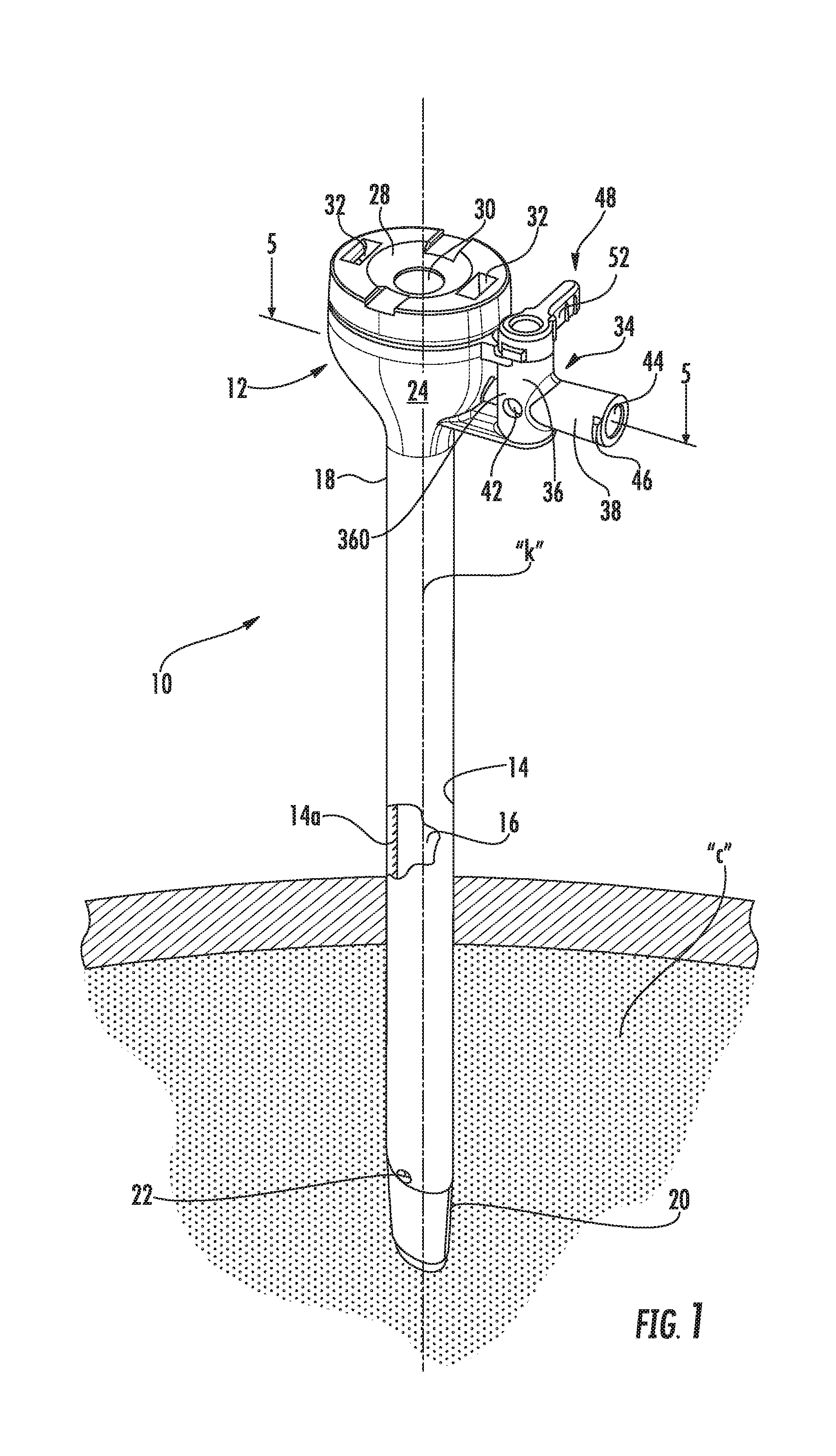
[0016] FIG. 1 is a perspective view of the surgical access apparatus in accordance with the present disclosure illustrating the access housing, the integrated fluid connector with the control valve mounted to the access housing, and the access member extending from the access housing;
[0017] FIG. 2 is an exploded perspective view of the access apparatus;
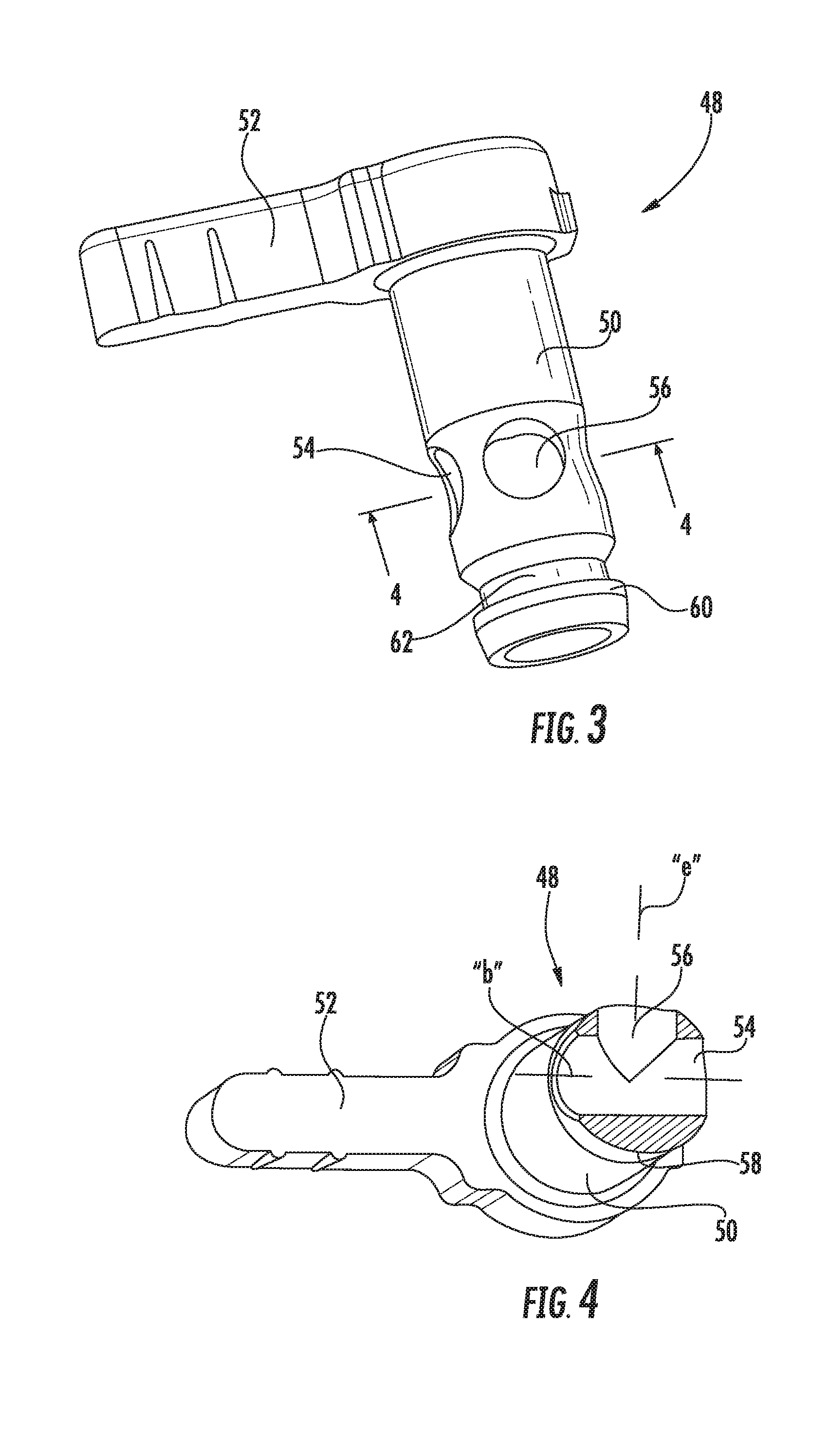
[0018] FIG. 3 is a first perspective view of the control valve of the access apparatus;
[0019] FIG. 4 is a second perspective view in partial cross-section of the control valve of the access apparatus;
[0020] FIG. 5 is a cross-sectional view taken along the lines 5-5 of FIG. 1 illustrating a first position of the control valve corresponding to a desufflation operative state of the access apparatus;
[0021] FIG. 6 is a cross-sectional view similar to the view of FIG. 5 illustrating a second position of the control valve corresponding to an insufflation operative state of the access apparatus; and
[0022] FIG. 7 is a cross-sectional view similar to the view of FIG. 5 illustrating a third position of the control valve corresponding to a closed operative state of the access apparatus.
DETAILED DESCRIPTION
[0023] Particular embodiments of the present disclosure are described hereinbelow with reference to the accompanying drawings; however, it is to be understood that the disclosed embodiments are merely examples of the disclosure and may be embodied in various forms. Well-known functions or constructions are not described in detail to avoid obscuring the present disclosure in unnecessary detail. Therefore, specific structural and functional details disclosed herein are not to be interpreted as limiting, but merely as a basis for the claims and as a representative basis for teaching one skilled in the art to employ the present disclosure in virtually any appropriately detailed structure.
[0024] The present disclosure has application in a variety of surgical access devices adapted for permitting percutaneous access to a target site. These access devices include, but are not limited to, trocars and/or cannulas, catheters, hand access devices, etc. The present disclosure is contemplated for use in various surgical procedures including, e.g., endoscopic, arthroscopic, thoracic, etc., but has particular application in a laparoscopic procedure performed in the abdominal cavity.
[0025] In the following description, as is traditional, the term "proximal" will refer to the portion of the instrument closest to the clinician while the term "distal" refers to the portion of the instrument most remote from the clinician.
[0026] Referring now to FIGS. 1-2, the access apparatus of the present disclosure is illustrated. The access apparatus 10 may be any member suitable for the intended purpose of accessing a body cavity and typically defines a passageway permitting introduction of instruments or the clinician's hand. The access apparatus 10 is particularly adapted for use in laparoscopic surgery where the abdominal or peritoneal cavity is insufflated with a suitable fluid or gas, e.g., CO.sub.2, to raise the cavity wall from the internal organs therein. The access apparatus 10 is typically used with an obturator assembly (not shown) which may be blunt, a non-bladed, or a sharp pointed instrument positionable within the passageway of the access apparatus 10. The obturator assembly is utilized to penetrate the abdominal wall to introduce the access apparatus 10 through the abdominal wall, and then subsequently is removed from the access apparatus 10 to permit introduction of the surgical instrumentation utilized to perform the procedure through the passageway.
[0027] The access apparatus 10 includes an access housing 12 and an access member 14 coupled to the access housing 12. The access housing 12 and the access member 14 collectively define a longitudinal axis "k", and have a longitudinal opening 16 therethrough (cut-away portions of FIGS. 1-2). The access member 14 may be cylindrical along at least a portion of its length and defines proximal end segment 18 and distal end segment 20. The access number 14 may be a cannula dimensioned for introduction within the abdominal cavity "c", and may include a port opening 22 in its outer wall 14a in communication with the longitudinal opening 16 and adjacent the distal end segment 20 for passage or release of insufflation fluids. In the alternative, the access member 14 may include a separate tube or channel for passage of the insufflation fluids. The access member 14, in the form of a cannula, may range from 3 mm to 15 mm. In embodiments, the access member 14 has a diameter of 5 mm or less.
[0028] The access housing 12 includes a housing segment 24, a closure element 26 disposed within the housing segment 24 and a cover 28. The housing segment 24 and the access member 14 may be monolithically formed as a single unit, or may be separate components secured to each other through conventional means. The housing segment 24 defines a semi-hemispherical or elliptical shape which tapers radially inwardly in the distal direction relative to the longitudinal axis "k". The closure element 26 is a zero closure valve configured to open upon passage of the surgical object therethrough, and close in the absence of the surgical object and/or in response to pressure provided by the underlying insufflation fluids. The closure element 26 may be a duckbill valve defining a slit 26a which provides a passageway through the closure element 26. Other zero closure valves are also contemplated. The access housing 12 also may include an object seal (not shown) configured to establish a sealing relation about a surgical object or instrument introduced therethrough. Suitable object seals include septum seals, single slit seals, double slit seals or the like.
[0029] The cover 28 is secured to the housing segment 24 through conventional means to enclose the closure element 26 and the interior of the access apparatus 10. The cover 28 includes a central opening 30 which leads to the longitudinal opening 16. The cover 28 may include diametrically opposed openings 32 for receiving sutures (not shown) for securing the access apparatus 10 relative to the surgical site.
[0030] With continued reference to FIGS. 1-2, the access housing 12 further includes a fluid connector 34 depending radially outwardly from the outer surface of the housing segment 24. The fluid connector 34 is integral with the housing segment 24, and, in one embodiment, is monolithically formed with the housing segment 24. In the alternative, the fluid connector 34 may be a separate component secured to the housing segment 24 through a mechanical coupling, adhesive, etc. The fluid connector 34 includes a valve chamber segment 36 and a coupler segment 38 depending radially outwardly relative to the valve chamber segment 36. The valve chamber segment 36 is arranged around a chamber axis "m" (FIG. 2) which, in one embodiment, is in general parallel relation with the central longitudinal axis "k". The valve chamber segment 36 defines an internal chamber 40 having a generally cylindrical configuration, and a single chamber exit port 42 extending through a side wall portion 36a thereof and in fluid communication with the internal chamber 40. The coupler segment 38 defines a central flow bore 44 therethrough and has an external male thread 46 (e.g., a luer coupling) for coupling to tubing of an insufflation system or source of pressurized fluids.
[0031] Referring now to FIGS. 3-4, in conjunction with FIG. 2, the access apparatus 10 includes a flow control valve 48 positionable relative to the valve chamber segment 36 of the fluid connector 34. The control valve 48 includes a valve stem 50 and a valve lever 52 coupled to the valve stem 50. The valve lever 52 is configured for engagement by the clinician to move, e.g., rotate, the control valve 48 relative to the valve chamber segment 36. The valve stem 50 is generally cylindrical in cross-section and is received within the correspondingly dimensioned internal chamber 40 of the valve chamber segment 36. The valve stem 50 includes a linear valve channel 54 arranged about a valve channel axis "b" and extending completely through opposed sides of the valve stem 50 and a valve intake port 56 on one side of the valve stem 50 and in communication with the valve channel 54. (FIG. 4) The valve intake port 56 is arranged about a valve intake port axis "e". The valve stem 50 is closed on the side opposing the valve intake port 56 (e.g., along the valve intake port axis "e") thereby defining a closed side 58 of the valve stem 50 diametrically opposing the valve intake port 56. In one embodiment, the valve intake port 56 is oriented at a 90.degree. interval relative to the valve channel 54 such that the valve intake port axis "e" of the valve intake port 56 is orthogonal to the valve channel axis "b" of the valve channel 54. Other orientations are also envisioned. The valve intake port 56 defines a smaller diameter than the diameter of the valve channel 54. The valve stem 50 further includes a mounting rib 60 adjacent its distal end which defines a mounting recess 62. The mounting rib 60 and/or the mounting recess 62 interact with corresponding structure (not shown) within the valve chamber segment 36 of the fluid connector 34 to secure the control valve 48 within the valve chamber segment 36.
[0032] The valve stem 50 can be cylindrical in shape with a valve channel that is linear and passes through the valve stem from a first side to a second side, opposite the first side. The intake port 56 is orthogonal to the valve channel and opposite the closed side 58, which is formed by a wall of the valve stem.
[0033] FIG. 5 illustrates, in cross-section, the assembled access apparatus 10. In FIG. 5, the flow passage "p" extending through the fluid connector 34 is also depicted, and is inclusive of the flow bore 44 of the coupler segment 38, the internal chamber 40 of the valve chamber segment 36 and the intermediate flow bore 64 extending between the valve chamber segment 36 and the housing segment 24 of the access housing 12. The flow passage "p" permits fluid communication between the insufflation fluid source, schematically identified as reference numeral 100, and the interior of the housing segment 24 distal of the closure element 26. The flow passage "p" is generally arranged around flow axis "s" which, in one embodiment, is orthogonal to the central longitudinal axis "k". Other arrangements are also envisioned.
[0034] FIG. 5 also illustrates a first position of the control valve 48 corresponding to the desufflation operative state of the access apparatus 10. In the first position, the valve intake port 56 of the valve stem 50 is in alignment with the intermediate flow bore 64 of the fluid connector 34 thereby establishing fluid communication with the access member 14, and the valve channel 54 is in alignment with the chamber exit port 42 of the valve chamber segment 36. The closed side 58 of the valve stem 50 is in alignment with, and intersects, the flow bore 44 of the coupler segment 38 thereby closing the fluid passage "p" to the insufflation fluid source 100. The closed side 58 of the valve stem 50 is disposed radial outward of the chamber exit port 42. Thus, in the first position, the insufflation fluids "f" may be conveyed from the access member 14 and the housing segment 24 into the fluid connector 34 and passed through the valve intake port 56 and the valve channel 54 of the valve stem 50, to rapidly exit the chamber exit port 42 of the valve chamber segment 36.
[0035] FIG. 6 illustrates a second position of the control valve 48 corresponding to the insufflation operative state of the access apparatus 10. In the second position, the closed side 58 of the valve stem 50 intersects, blocks or covers the chamber exit port 42 of the valve chamber segment 36 while the valve channel 54 of the valve stem 50 is in alignment with the flow bore 44 of the coupler segment 38 thereby completely opening the flow passage "p" through the fluid connector 34. Thus, in the second position, the insufflation fluids "f" will pass from the insufflation fluid source 100 through the fluid connector 34 and into the housing segment 24 and/or access member 14 distal of the closure element 26 within the access housing 12.
[0036] FIG. 7 illustrates a third position of the control valve 48 corresponding to the closed operative state of the access apparatus 10. In the third position, the closed side 58 of the valve stem 50 is disposed radial inward of the chamber exit port 42, and is arranged to intersect or block the intermediate flow bore 64 of the fluid connector 34 thereby closing the fluid passage "p" of the fluid connector 34 relative to the access member 14, e.g. preventing egress of insufflation fluids "f" from the access member 14. In the third state, the pneumoperitoneum is maintained without passage of insufflation fluids between the insufflation fluid source 100 and the access member 14. The insufflation fluid source 100 also may be deactivated through, e.g., closing a valve associated with the insufflation fluid source 100 or turning the source to an off-mode of operation.
[0037] The use of the access apparatus 10 will now be discussed. The access apparatus 10 is introduced through the abdominal wall to access the underlying abdominal cavity. In accordance with one methodology, an obturator (not shown) is positioned within the access apparatus 10 and advanced through the abdominal wall, e.g., through a previously created incision in the abdominal wall or through an opening created by the obturator, to position at least the distal end segment 20 of the access member 14 within the abdominal cavity "c" as depicted in FIG. 1. Prior to accessing the abdominal cavity "c", the abdominal cavity "c" may be at least partially or fully expanded with insufflation fluids, CO.sub.2, introduced via an insufflation needle to establish a pneumoperitoneum. A surgical object, e.g., a laparoscopic surgical instrument such as a grasper, scissor, electrosurgical device, stapler, etc. may be advanced through the access apparatus 10 and into the underlying surgical site to perform a surgical task. If, during the procedure, insufflation fluids are required to establish or maintain the pneumoperitoneum, the control valve 48 may be oriented to the position of FIG. 6 corresponding to the insufflation operative state thereby permitting passage of insufflation fluids from the insufflation fluid source 100 through the fluid connector 34 and into the access member 14 for delivery within the abdominal cavity "c". When the desired state of pneumoperitoneum is achieved, the control valve 48 may be manipulated to the position of FIG. 7 corresponding to the closed operative state which blocks egress of the insufflation fluids through the flow passage "p" of the fluid connector 34 and through the control valve 48. Upon completion of the surgery or when it is determined that rapid desufflation of the abdominal cavity is required, the control valve 48 is maneuvered to the first position depicted in FIG. 5 corresponding to the desufflation operative state, which aligns the valve intake port 56 of the valve stem 50 with the intermediate flow bore 64 of the fluid connector and aligns the valve channel 54 with the chamber exit port 42 of the valve chamber segment 36. Thus, in the first position, the insufflation fluids "f" may pass through the access member 14 and the access housing 12 into the fluid connector 34 through the valve intake port 56 and the valve channel 54 and rapidly exit the chamber exit port 42 of the valve chamber segment 36.
[0038] Thus, the integrated fluid connector 34 and control valve 48 of the present disclosure provides the ability of quick desufflation without requiring removal of a detachable seal system. Only one exit hole, chamber exit port 42, is required in the side wall of the fluid connector 34 and, in combination with the respective configurations of the valve channel 54 and the valve intake port 56 of the valve stem 50, permits ready transition between the three operative states of the access apparatus 10.
[0039] The above description and the drawings are provided for the purpose of describing embodiments of the present disclosure and are not intended to limit the scope of the disclosure in any way. It will be apparent to those skilled in the art that various modifications and variations can be made without departing from the spirit or scope of the disclosure. Thus, it is intended that the present disclosure cover the modifications and variations of this disclosure provided they come within the scope of the appended claims and their equivalents.
* * * * *
D00000
D00001
D00002
D00003
D00004
XML
uspto.report is an independent third-party trademark research tool that is not affiliated, endorsed, or sponsored by the United States Patent and Trademark Office (USPTO) or any other governmental organization. The information provided by uspto.report is based on publicly available data at the time of writing and is intended for informational purposes only.
While we strive to provide accurate and up-to-date information, we do not guarantee the accuracy, completeness, reliability, or suitability of the information displayed on this site. The use of this site is at your own risk. Any reliance you place on such information is therefore strictly at your own risk.
All official trademark data, including owner information, should be verified by visiting the official USPTO website at www.uspto.gov. This site is not intended to replace professional legal advice and should not be used as a substitute for consulting with a legal professional who is knowledgeable about trademark law.