Inflatable Bed
Liu; Tsung Hsi
U.S. patent application number 15/697430 was filed with the patent office on 2019-03-07 for inflatable bed. The applicant listed for this patent is Tsung Hsi Liu. Invention is credited to Tsung Hsi Liu.
| Application Number | 20190069691 15/697430 |
| Document ID | / |
| Family ID | 65517489 |
| Filed Date | 2019-03-07 |


| United States Patent Application | 20190069691 |
| Kind Code | A1 |
| Liu; Tsung Hsi | March 7, 2019 |
INFLATABLE BED
Abstract
An inflatable bed includes an upper body, a lower body, and a closed chamber space formed between the upper body and the lower body. The inflatable bed includes a plurality of connecting members therein. The connecting members are spaced a determined distance apart from each other and arranged longitudinally and transversely inside the inflatable bed for connecting the upper body with the lower body. Each of the connecting members is a thin ring-like structure. When the inflatable bed is inflated, the connecting members arranged in the longitudinal and transverse directions provide a bubble-like effect, thereby enhancing the comfort for the user to lie thereon. Further, the inflatable bed is light and small in size after collapsed, which is advantageous for camping and mountaineering.
| Inventors: | Liu; Tsung Hsi; (Yilan County, TW) | ||||||||||
| Applicant: |
|
||||||||||
|---|---|---|---|---|---|---|---|---|---|---|---|
| Family ID: | 65517489 | ||||||||||
| Appl. No.: | 15/697430 | ||||||||||
| Filed: | September 6, 2017 |
| Current U.S. Class: | 1/1 |
| Current CPC Class: | A45F 2003/001 20130101; A45F 3/00 20130101; A47C 17/64 20130101; A47C 27/081 20130101; A47C 27/087 20130101 |
| International Class: | A47C 27/08 20060101 A47C027/08; A47C 17/64 20060101 A47C017/64; A45F 3/00 20060101 A45F003/00 |
Claims
1. An inflatable bed, comprising an upper body, a lower body, and a closed chamber space formed between the upper body and the lower body, characterized by: the inflatable bed including a plurality of connecting members therein, the connecting members being spaced a determined distance apart from each other and arranged longitudinally and transversely inside the inflatable bed for connecting the upper body with the lower body, each of the connecting members being a thin ring-like structure.
2. The inflatable bed as claimed in claim 1, wherein the chamber space is configured to fill the inflatable bed with air.
3. The inflatable bed as claimed in claim 1, wherein the upper body and each of the connecting members are joined together by a press-fit technique to form a bonded portion so that the upper body is connected with the connecting member.
4. The inflatable bed as claimed in claim 1, wherein the lower body and each of the connecting members are joined together by a press-fit technique to form a bonded portion so that the lower body is connected with the connecting member.
5. The inflatable bed as claimed in claim 3, wherein the press-fit technique is high frequency heating.
6. The inflatable bed as claimed in claim 4, wherein the press-fit technique is high frequency heating.
7. The inflatable bed as claimed in claim 3, wherein the bonded portion is in the form of a circle, a rectangle or a strip.
8. The inflatable bed as claimed in claim 4, wherein the bonded portion is in the form of a circle, a rectangle or a strip.
Description
FIELD OF THE INVENTION
[0001] The present invention relates to an inflatable bed, and more particularly to a connecting structure of an inflatable bed.
BACKGROUND OF THE INVENTION
[0002] For mountaineering or camping, people usually use a soft cushion to enhance the comfort of ling on the ground and stop the surface temperature. The soft cushion is made of a soft material, so it can enhance the comfort for the user to lie thereon. But, because of its solid structure, the soft cushion is heavy in weight and large in size, so it is inconvenient for carrying. Therefore, an inflatable mattress is developed on the market. Although it can reduce the weight and the size after collapsed, the internal structure of the inflatable mattress is provided with a number of pull strips. As a result, the inflatable mattress is still somewhat heavy.
[0003] Accordingly, the inventor of the present invention has devoted himself based on his many years of practical experiences to solve these problems.
SUMMARY OF THE INVENTION
[0004] In view of the shortcomings of the prior art, the primary object of the present invention is to provide an inflatable bed which is light in weight and comfortable for use and has a simple structure and can be carried conveniently and has a low cost and other advantages, meeting the needs of industry and consumers.
[0005] In order to achieve the aforesaid object, the inflatable bed of the present invention comprises an upper body, a lower body, and a closed chamber space formed between the upper body and the lower body. The inflatable bed includes a plurality of connecting members therein. The connecting members are spaced a determined distance apart from each other and arranged longitudinally and transversely inside the inflatable bed for connecting the upper body with the lower body. Each of the connecting members is a thin ring-like structure. When the chamber space inside the inflatable bed is inflated, the connecting members arranged in the longitudinal and transverse directions provide a bubble-like effect, thereby enhancing the comfort for the user to lie on the inflatable bed. Further, the inflatable bed is light and small in size after collapsed, which is advantageous for camping and mountaineering.
[0006] Preferably, the upper body and each of the connecting members are joined together by a press-fit technique, such as high frequency heating, to form a bonded portion so that the upper body is connected with the connecting member.
[0007] Preferably, the lower body and each of the connecting members are joined together by a press-fit technique, such as high frequency heating, to form a bonded portion so that the lower body is connected with the connecting member.
[0008] Preferably, the bonded portion may be of various shapes, such as a circle, a rectangle, a strip, or a polygon, but not limited thereto.
BRIEF DESCRIPTION OF THE DRAWINGS
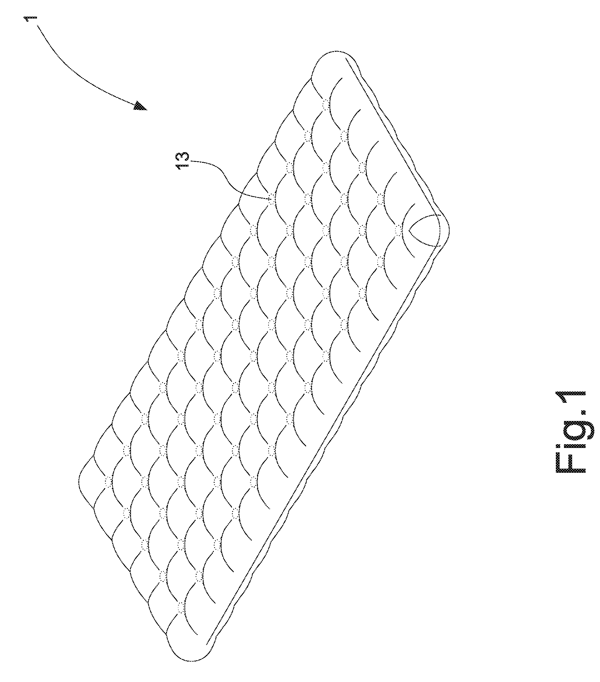
[0009] FIG. 1 is a perspective view of the present invention;
[0010] FIG. 2 is a partial sectional view of the present invention in an inflated state;
[0011] FIG. 3 is a partial sectional view of the present invention in a deflated state; and
[0012] FIG. 4 is a perspective view of another embodiment of the present invention, showing the bonded portion in the form of a strip.
DETAILED DESCRIPTION OF THE PREFERRED EMBODIMENTS
[0013] Embodiments of the present invention will now be described, by way of example only, with reference to the accompanying drawings.
[0014] As shown in FIG. 1 and FIG. 2, the present invention discloses an inflatable bed 1. The inflatable bed 1 comprises an upper body 11, a lower body 12, and a closed chamber space 10 formed between the upper body 11 and the lower body 12. The present invention is characterized in that the inflatable bed 1 includes a plurality of connecting members 2 therein. The connecting members 2 are spaced a determined distance apart from each other and arranged longitudinally and transversely inside the inflatable bed 1 for connecting the upper body 11 with the lower body 12.
[0015] Each connecting member 2 is a thin ring-like structure. The upper body 11 and the connecting member 2 are joined together by a press-fit technique, such as high frequency heating, to form a bonded portion 13 so that the upper body 11 is connected with the connecting member 2. The lower body 12 is connected with the connecting member 2 in the same manner.
[0016] According to the above-described structure, when the chamber space 10 inside the inflatable bed 1 is inflated, the connecting members 2 spaced a determined distance apart from each other and arranged longitudinally and transversely are inflated and connected between the upper body 11 and the lower body 12 to provide a bubble-like effect, thereby enhancing the comfort for the user to lie on the inflatable bed. Further, after the inside of the chamber space 10 is deflated (as shown in FIG. 3), the connecting members 2 in the form of a thin ring-like structure are light and small in size after collapsed, which is advantageous for camping and mountaineering.
[0017] The bonded portion 13 may be of various shapes, such as a circle. As shown in FIG. 4, the bonded portion 14 is in the form of a strip to change the appearance thereof.
[0018] Although particular embodiments of the present invention have been described in detail for purposes of illustration, various modifications and enhancements may be made without departing from the spirit and scope of the present invention. Accordingly, the present invention is not to be limited except as by the appended claims.
* * * * *
D00000
D00001
D00002
D00003
D00004
XML
uspto.report is an independent third-party trademark research tool that is not affiliated, endorsed, or sponsored by the United States Patent and Trademark Office (USPTO) or any other governmental organization. The information provided by uspto.report is based on publicly available data at the time of writing and is intended for informational purposes only.
While we strive to provide accurate and up-to-date information, we do not guarantee the accuracy, completeness, reliability, or suitability of the information displayed on this site. The use of this site is at your own risk. Any reliance you place on such information is therefore strictly at your own risk.
All official trademark data, including owner information, should be verified by visiting the official USPTO website at www.uspto.gov. This site is not intended to replace professional legal advice and should not be used as a substitute for consulting with a legal professional who is knowledgeable about trademark law.