Device For Dissipating Forces On A Helmet
Mesko; Zoltan ; et al.
U.S. patent application number 16/174873 was filed with the patent office on 2019-03-07 for device for dissipating forces on a helmet. The applicant listed for this patent is EXERO LABS LLC. Invention is credited to Paul DiTullio, John D. Fiegener, Thomas Gernetzke, Marcus R. Hanna, William P. Liteplo, Zoltan Mesko, Benjamin R. Rizzo.
| Application Number | 20190069624 16/174873 |
| Document ID | / |
| Family ID | 57218338 |
| Filed Date | 2019-03-07 |


View All Diagrams
| United States Patent Application | 20190069624 |
| Kind Code | A1 |
| Mesko; Zoltan ; et al. | March 7, 2019 |
DEVICE FOR DISSIPATING FORCES ON A HELMET
Abstract
A device for dissipating forces on a helmet is described. The device includes first and second dissipation layers, each having a leaf spring. A helmet including such device is further described. A leaf spring for dissipating forces on a curved object is also described.
| Inventors: | Mesko; Zoltan; (Chagrin Falls, OH) ; Rizzo; Benjamin R.; (Pittsburgh, PA) ; Fiegener; John D.; (Marblehead, MA) ; DiTullio; Paul; (Malborough, MA) ; Liteplo; William P.; (Middleton, MA) ; Gernetzke; Thomas; (Beverly, MA) ; Hanna; Marcus R.; (South Boston, MA) | ||||||||||
| Applicant: |
|
||||||||||
|---|---|---|---|---|---|---|---|---|---|---|---|
| Family ID: | 57218338 | ||||||||||
| Appl. No.: | 16/174873 | ||||||||||
| Filed: | October 30, 2018 |
Related U.S. Patent Documents
| Application Number | Filing Date | Patent Number | ||
|---|---|---|---|---|
| 15571438 | Nov 2, 2017 | |||
| PCT/US2016/030943 | May 5, 2016 | |||
| 16174873 | ||||
| 62158189 | May 7, 2015 | |||
| Current U.S. Class: | 1/1 |
| Current CPC Class: | A42B 3/125 20130101; F16F 1/185 20130101; F16F 1/368 20130101; A42B 3/064 20130101; A42B 3/069 20130101 |
| International Class: | A42B 3/06 20060101 A42B003/06; A42B 3/12 20060101 A42B003/12; F16F 1/18 20060101 F16F001/18; F16F 1/368 20060101 F16F001/368 |
Claims
1. A helmet comprising: a shell portion configured to receive a user's head; an outer dissipation layer configured to dissipate forces; and an inner dissipation layer configured to further dissipate forces; wherein at least one of the outer dissipation layer and the inner dissipation layer is coupled with the shell portion.
2. The helmet according to claim 1, wherein at least one of the outer dissipation layer and the inner dissipation layer includes a leaf spring.
3. The helmet according to claim 1, wherein the outer dissipation layer is removably coupled with the shell portion and the inner dissipation layer second dissipation layer is removably coupled with at least one of the shell portion and the outer dissipation layer.
4. The helmet according to claim 1, wherein the outer dissipation layer includes an outer leaf spring having a fixed point connected to the shell portion and a free point configured to move relative to the shell portion; and wherein the inner dissipation layer includes an inner leaf spring having a fixed point connected to at least one of the shell portion and the outer dissipation layer and a free point configured to move relative to the shell portion.
5. The helmet according to claim 4, wherein the outer dissipation layer is removably coupled with the shell portion and the inner dissipation layer is removably coupled with at least one of the shell portion and the outer dissipation layer.
6. The helmet according to claim 4, wherein the inner dissipation layer includes: a longitudinal leaf spring with at least two fixed points and a free arm and a multi-arm leaf spring with at least one fixed point and at least two arms extending from the at least one fixed point.
7. The helmet according to claim 6, wherein the outer dissipation layer includes a shield portion configured to cover a substantial portion of a front area of the shell portion.
8. The helmet according to claim 1, wherein the inner dissipation layer comprises a foam.
9. The helmet according to claim 8, wherein the inner dissipation layer comprises a plurality of foam layers.
10. The helmet according to claim 1 comprising at least one strap, wherein at least one of the outer dissipation layer and the inner dissipation layer is attached to the shell by the at least one strap.
11. A device for dissipating forces on a helmet comprising: a first dissipation layer having at least one leaf spring; and a second dissipation layer functionally coupled with first dissipation layer and having at least another leaf spring.
12. A device according to claim 11, wherein the first dissipation layer and the second dissipation layer are configured to be selectively coupled with each other.
13. The device according to claim 12, wherein the second dissipation layer includes: a longitudinal leaf spring with at least two fixed points and a free arm and a multi-arm leaf spring with at least one fixed point and at least two arms extending from the at least one fixed point.
14. The device according to claim 13, wherein the first dissipation layer includes a shield portion configured to cover the plurality of leaf springs of the second dissipation layer.
15. The device according to claim 14, wherein the second dissipation layer includes at least three outer leaf springs each extending from the shield portion.
16. The device according to claim 11, wherein the at least one leaf spring of the first dissipation layer is made of metal and the at least another leaf spring of the second dissipation layer is made of a composite material.
17. A leaf spring for dissipating forces on a curved object comprising: an anchor point configured to receive a fastener; and a free arm having a length and extending away from the anchor point, wherein the free arm includes a plurality of bend portions configured to dissipate forces substantially equally along the length of the free arm.
18. The leaf spring according to claim 17, wherein the at least one of the plurality of bend portions of the free arm have a generally parabolic shape.
19. The leaf spring according to claim 17, wherein the at least two of the plurality of bend portions of the free arm have a generally parabolic shape, with one of the bend portions convex and the other one of the bend portions concave.
20. The leaf spring according to claim 17, wherein the anchor point includes a raised portion adjacent to at least one of the plurality of bend portions.
Description
RELATED APPLICATIONS
[0001] The present patent document is a continuation of U.S. patent application Ser. No. 15/571,438, entitled "DEVICE FOR MINIMIZING IMPACT OF COLLISIONS FOR A HELMET," filed on Nov. 2, 2017, which application is a 371 national stage application of PCT/US2016/030943, entitled "DEVICE FOR MINIMIZING IMPACT OF COLLISIONS FOR A HELMET," filed on May 5, 2016, which application claims priority to U.S. Provisional Patent Application No. 62/158,189, entitled "DEVICE FOR MINIMIZING IMPACT OF COLLISIONS FOR A SPORTS HELMET," filed on May 7, 2015, the entire contents of each of which are incorporated herein by reference in their entirety.
BACKGROUND
[0002] The present disclosure relates to head protection equipment for dissipating forces from the impact of collisions.
[0003] Contact sports are facing increasing scrutiny as more is learned about concussion and subconcussive head blows. As nutritional and exercise sciences combine to produce larger, faster, stronger athletes who are capable of hitting with greater force, and sports like football increase in popularity and participation, medical experts are noting risks of potential injuries, particularly head injuries, high-impact sports.
[0004] While dramatic hits which cause individuals to lose consciousness and cause a stoppage of play or work represent much of what the public regards as the largest safety issues among football players and laborers respectively, it is becoming evident that the routine hits sustained on every play, particularly those on the offensive and defensive lines in football, may also have an additive and deleterious effect on the health of the brain. Such impacts are not merely restricted to games, but may be sustained in practice or training sessions with teammates. The effect of hundreds of impacts per season, multiplied across numerous years, may be linked to such conditions as chronic traumatic encephalopathy (CTE), which can only be affirmatively diagnosed post mortem but can manifest itself in the form of depression, confusion, aggression, memory loss, dementia, or any combination of the preceding. In certain individuals these symptoms arise immediately; in others, it may take years before they emerge. In any case, when evidence of CTE manifests, the effects appear to be generally irreversible and there is no known cure for CTE.
[0005] Football helmets were originally designed to prevent skull fractures, and have served this purpose very well. However, when plastic helmets were introduced after an era of leather helmets, many players gained confidence in the protection they afforded and started using their helmets to launch forward to make a tackle or a successful block. Furthermore, offensive and defensive linemen come into frequent helmet-to-helmet contact with each other. When the plastic helmet was introduced, skull fractures decreased, but more difficult to detect consequences of impact such as concussions appear to have increased, possibly because of the new techniques players employed in using the helmet.
[0006] One attempted solution is a soft-shell covers to cushion the head from a blow. However, while the shells may reduce the overall amount of force of a hit, they may actually increase axial loading forces. When two hard-shell helmets impact one another, the two helmets have the ability to glance off one another, minimizing the chance for axial loading to occur. However, when a soft-shell helmet gets hit by a hard-shell helmet (or by another soft-shell helmet), the soft shell gives in on impact and the helmet may more easily transfer momentum onto the spinal cord.
[0007] Another attempted solution has been the use of shock strips, which act as cushions to impacts to the helmet, but this device relies on the end user to affix them properly to the surface of the helmet. Shock strips may also reduce the glancing effect of helmets, as described above.
[0008] It is desirable to minimize the amount of force absorbed by the head of a participant in a contact sport using a resilient material.
SUMMARY
[0009] According to one aspect of the present disclosure, a helmet is provided, the helmet including a shell portion configured to receive a user's head, an outer dissipation layer configured to dissipate forces, and an inner dissipation layer configured to further dissipate forces. At least one of the outer dissipation layer and the inner dissipation layer is coupled with the shell portion.
[0010] The outer and/or inner dissipation layer may include a leaf spring. The outer dissipation layer may be removably coupled with the shell portion of the helmet and the inner dissipation layer may be removably coupled with at least the shell portion and/or the outer dissipation layer. The outer dissipation layer may include an outer leaf spring having a fixed point connected to the shell portion and a free point configured to move relative to the shell portion. The inner dissipation layer may include an inner leaf spring having a fixed point connected to at least one of the shell portion and the outer dissipation layer and a free point configured to move relative to the shell portion. The inner leaf spring may be made of metal and the outer leaf spring may be made of a composite material.
[0011] The outer dissipation layer may be removably coupled with the shell portion and the second dissipation layer inner dissipation layer may be removably coupled with at least one of the shell portion and the outer dissipation layer. The inner dissipation layer may include a longitudinal leaf spring with at least two fixed points and a free arm, and a multi-arm leaf spring with at least one fixed point and at least two arms extending from the fixed point.
[0012] The outer dissipation layer may include a shield portion configured to cover a substantial portion of a front of the shell portion of the helmet. The outer dissipation layer may also include at least three outer leaf springs each extending from the shield portion, with each of the outer leaf springs including a free point configured to move relative to the shell portion.
[0013] In another aspect of the present disclosure, a device for dissipating forces on a helmet is provided, the device including a first dissipation layer having at least one leaf spring and a second dissipation layer coupled with the first dissipation layer and having another leaf spring.
[0014] In another aspect of the present disclosure, a leaf spring for dissipating forces on a curved object is provided, the leaf spring including an anchor point configured to receive a fastener and a free arm having a length and extending away from the anchor point, wherein the free arm includes a plurality of bend portions configured to dissipate forces substantially equally along the length of the free arm.
[0015] At least one of the plurality of bend portions may include a generally parabolic shape. The bend portions may include convex and concave parabolic shapes.
[0016] The anchor point may include a raised portion adjacent to one of the bend portions. The free arm may have an end portion configured to receive another fastener.
[0017] In another aspect, portions of an impact mitigation device may be constructed in order to provide a space between a portion of the device and the helmet to which it is attached in order to facilitate rotational and inward shifts upon contact, in order to dissipate forces.
[0018] In another aspect, an impact mitigation device may be attached to a helmet by one or more straps, which are attached to the device and hooked onto the helmet to secure the device.
[0019] In another aspect, an impact mitigation device may be provided with one or more inner disippation layers which may in some embodiments be foam layers, disposed between a leaf spring and/or base of the device and an outer surface of the helmet.
[0020] Further aspects, features, and advantages of the disclosed embodiments will become apparent from consideration of the following description and the appended claims when taken in connection with the accompanying drawings.
BRIEF DESCRIPTION OF THE DRAWINGS
[0021] Preferred embodiments are described below, by way of example only with reference to the accompanying drawings in which:
[0022] FIG. 1A is a view of a prior art design, namely the ProCap product;
[0023] FIG. 1B is a view of another prior art design, namely the Guardian Cap product.
[0024] FIGS. 2-3 are views of an impact mitigation device comprising a single leaf spring in accordance with one embodiment of the present disclosure;
[0025] FIG. 4 is a view of an impact mitigation device comprising three leaf springs and a number of connecting members in accordance with one embodiment of the present disclosure;
[0026] FIG. 5 is a view of an impact mitigation device comprising three leaf springs and a number of connecting members in accordance with another embodiment of the present disclosure;
[0027] FIGS. 6A-6B are views of an impact mitigation device comprising five leaf springs and a number of connecting members in accordance with another embodiment of the present disclosure;
[0028] FIG. 7 is a view of an impact mitigation device comprising five leaf springs and a number of connecting members in accordance with another embodiment of the present disclosure;
[0029] FIGS. 8A-8F are views of an impact mitigation device comprising five leaf springs and a number of connecting members in accordance with another embodiment of the present disclosure;
[0030] FIGS. 9A-9B are views of an impact mitigation device with a dual-layer configuration in accordance with another embodiment of the present disclosure;
[0031] FIGS. 10A-10F are views of an impact mitigation device with a dual-layer configuration in accordance with another embodiment of the present disclosure;
[0032] FIG. 11 is a view of a leaf spring for dissipating forces on a curved object;
[0033] FIGS. 12A and 12B are cross-sectional views of an impact mitigation device disposed over a helmet and constructed in accordance with the principles of the present disclosure;
[0034] FIG. 13 is a cross-sectional view of an impact mitigation device disposed over a helmet and constructed in accordance with the principles of the present disclosure;
[0035] FIG. 14 is a perspective view of an impact mitigation device disposed over a helmet and showing a plurality of straps for securing the device to the helmet;
[0036] FIGS. 15A-15C are perspective views of an impact mitigation device including at least one inner dissipation layer in accordance with the principles of the present disclosure; and
[0037] FIG. 15D is a schematic view illustrating the placement of inner dissipation layers on the underside of an impact mitigation device in accordance with the principles of the present disclosure.
DETAILED DESCRIPTION
[0038] It is to be understood that the figures are schematic and do not show the various components to their actual scale. In many instances, the figures show scaled up components to assist the reader.
[0039] "Substantially" or derivatives thereof as used herein will be understood to mean significantly or in large part. The terms "substantially" or "about" used herein with reference to a quantity includes variations in the recited quantity that are equivalent to the quantity recited, such as an amount that is equivalent to the quantity recited for an intended purpose or function.
[0040] As used herein, the term "dissipation" when used in conjunction with a portion or layer of a device refers to the effective reduction in magnitude of a force that a user who is employing the employing the device would otherwise experience. This reduction may be derived from absorption, redistribution, redirection, of deflection of the force, or any other way of reducing impact of a force, including dissipation. Therefore, a "dissipation layer" as used herein may be an absorption layer, or any other type of impact-reducing layer, as would be appreciated by a person of skill in the art.
[0041] It is an object of the present disclosure to describe a device which may effectively reduce the impact of hits to the helmet of an individual while remaining aesthetically pleasing and requiring minimal adjustment to existing helmet design. Prior attempts at modifying helmets, such as the ProCap (FIG. 1A) and the Guardian Cap (FIG. 1B), have been somewhat effective in reducing some of the impact of hits to the helmet, but have suffered from increasing the dimensions and the bulk of the helmet, which makes them unwieldy. Additionally, these prior attempts may also reduce the glancing effect of helmets. Football players, other athletes, manual laborers, and military personnel need to be able to run and to turn their heads during work and play, and excess weight or helmets that are skewed too greatly in one dimension make athletic activity awkward. A lightweight solution which does not interfere or minimally interferes with field of vision would represent a better solution.
[0042] One way to potentially reduce the impact force of a hit is to increase the distance between the impact point and the region to be protected: the skull and the brain. Modifications to the interior of a helmet are of lesser importance compared to the exterior because there is not enough space to slow a violent impact due to the tight fit of the helmet on the head. Giving the force applied more time (by increasing distance) to decelerate or to be absorbed improves the potential to decrease the magnitude of the force.
[0043] The embodiments of the present disclosure provide an increased space for slowing and reduction of force by employing at least one leaf spring in their construction. A leaf spring is an arc-shaped, resilient spring which serves to dampen impacts. The leaf springs of the disclosed device may be mono-leaf springs in that they may comprise a single arc and may not have a secondary structure with which they cooperate for purposes of their spring action. Even when multiple leaf springs are present, each leaf spring may be an independent mono-leaf.
[0044] The leaf springs of the present embodiments have an intrinsic hardness but are also resilient in such a way that allows an impact to be absorbed while ensuring the leaf spring returns to its original shape. The leaf spring is held a distance away from the surface of the helmet, and upon impact flattens, in some cases flattening to the point of contacting the helmet. The leaf springs of the present disclosure can be made in different materials (steel, titanium, polymer, plastic, carbon fiber, nylon, polycarbonate, composites, thermoplastic materials, natural and synthetic rubbers, and so forth.) The material used to make the leaf springs, or the entire device, will be selected to fit the impact force anticipated at the level of football or other activity for which the helmet is intended; for example a grade school player's helmet may have a device of lighter construction than that intended for a collegiate or professional player.
[0045] Another material from which the device may be constructed may be a thermoplastic composite which incorporates a fiberglass resin. Materials of this type are lightweight but strong. In some cases, the individual fibers of the fiberglass may be woven and combined with the thermoplastic resin in such a way as to maximize structural integrity. The device may also be constructed of multiple materials to provide a combination of impact reduction, durability, and ease of manufacturing.
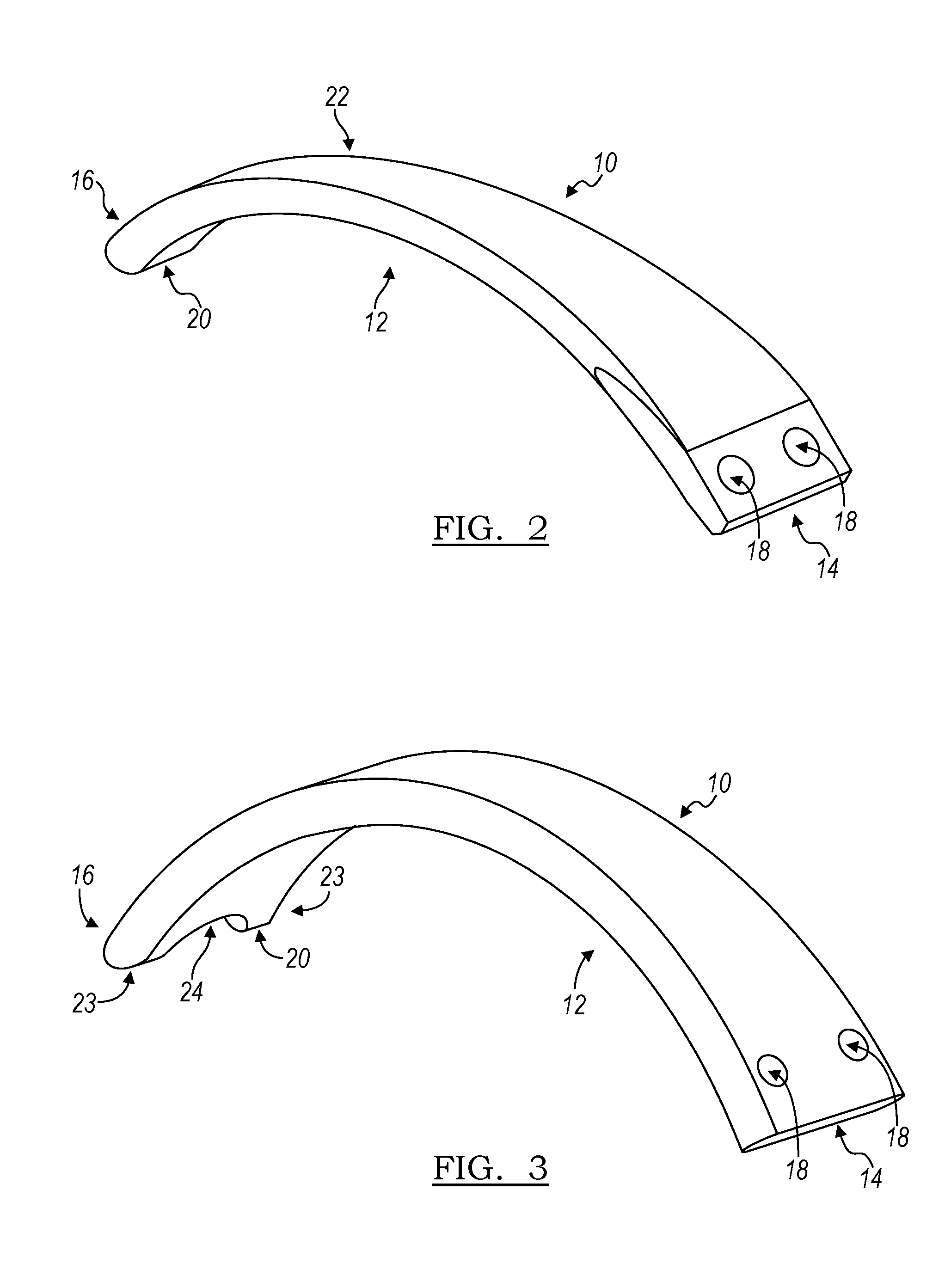
[0046] In the first embodiment as depicted in FIGS. 2-3, the device 10 may comprise a single leaf spring 12. Such a device has a first end 14 and a second end 16, with the leaf spring 12 extending from said first end 14 to the second end 16. The first end 14 has two screw holes 18 formed therethrough so that the device can be easily connected to the exterior of the helmet above the central portion of the facemask, where many helmets already have a pair of screws for attaching the facemask. The device could also be made without the screw holes and instead be attached to the helmet via at least one clip, at least one snap, at least one buckle, adhesive, Velcro, or other permanent or temporary mechanism. Alternatively, the device 10 and the helmet may be one unitary component, in that the device 10 is molded as an integral part of the helmet. Such modes of attachment are merely exemplary and should not be taken to be limiting, and apply to all embodiments of devices described herein.
[0047] In the device of FIGS. 2-3, the leaf spring 12 then extends back and up the center of the helmet to the crown of the helmet, or just past the crown, where the second end 16 is positioned away from the base and rests upon or is slightly spaced apart from the exterior of the helmet. In one embodiment, the device has at its second end a foot 20, which can be a disc-like or cylinder-shaped protrusion which sits on the exterior of the helmet in its pre-impact configuration and which facilitates sliding along the surface of the helmet on impact. In the embodiment illustrated in FIG. 3, the device 10 has a foot 20 which has two helmet-contacting portions 23 separated by an arc 24.
[0048] A leaf spring 12 as described herein may be of a variety of thicknesses. For instance, a plastic leaf spring may be about 2 millimeters (mm) to about 10 mm thick, or between about 4 mm and about 8 mm thick, or about 7 mm thick. In the case of a metal leaf spring, for instance one made of steel, the leaf spring 12 may be at one point about 1 mm to about 5 mm thick, or more particularly about 2 mm to about 3 mm thick.
[0049] The device 10 may comprise a leaf spring 12 having one of a variety of profiles. For instance, in the case of the embodiment of FIG. 2, the leaf spring 12 has a tapering profile, with the first end 14 being the widest part of the device 10, the device tapering through point 22 to the thinnest portion of the device at second end 16. Contrarily, the embodiment depicted in FIG. 3 has substantially the same width across its entire length.
[0050] In further embodiments, such as are shown in FIGS. 4 and 5, the device may comprise multiple leaf springs attached to a unitarily-formed base. The base may comprise a variety of designs. For instance, in the device 110 of FIG. 4, the base 130 is a small extension from the first end 115 of central leaf spring 112. In contrast, in the embodiment of FIG. 5, the base 230 runs circumferentially around the exterior of the helmet from left end 232 to right end 232. The base 230 would, upon attachment to a helmet, lie approximately over the forehead and extending substantially from temple to temple, the portions over the temple representing a right end and a left end of the base.
[0051] In the embodiments of FIGS. 4-5, one side leaf spring 113 is attached at its first end (or anchored end) 117 to the end of the base 130 and extends to its second end 119 just past the left ear; a second side leaf spring 111 is similarly attached over the right ear. A central leaf spring 112 runs centrally up the forehead area and past the crown, mirroring the embodiment of FIGS. 2 and 3. Such a device covers the entire frontal hemisphere of the helmet, where most concussion-causing hits occur. Additionally or alternatively, connecting members 132/134 may connect the base to a leaf spring, or the base to another connecting member, in order that maximal force be absorbed throughout the entirety of the device, or a specific target area for specific protection of the back or side of the helmet.
[0052] FIG. 5 illustrates how different connecting members may provide structure to the device 210. First connecting members 238 originate from the side leaf springs 211/213 and extend arcuately to the central leaf spring 210. Second connecting members originate from the base 230 and extend to the first connecting member 238, meeting at intersection point 240.
[0053] In the embodiments of FIGS. 4-5, each of the leaf springs 111/112/113/211/212/213 may comprise a foot at its second or free end, allowing for sliding and resilient action of the leaf spring. Connecting members which may or may not be leaf springs connect the three leaf springs together to give the device its overall structure.
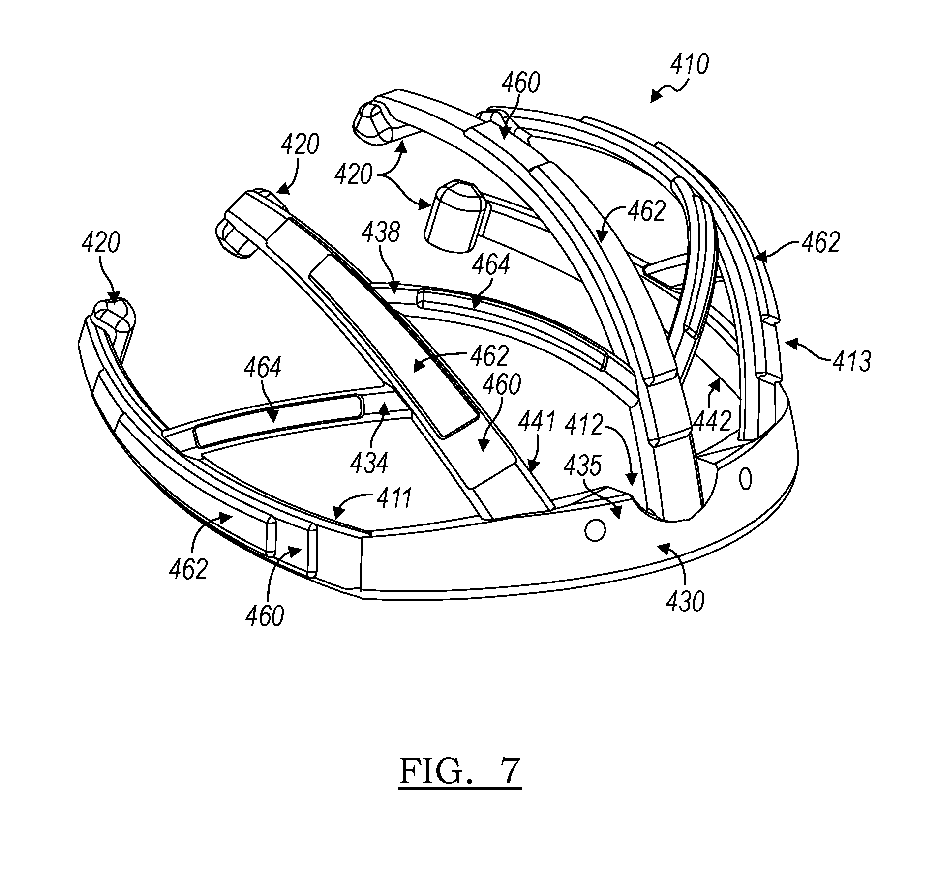
[0054] The embodiments of FIGS. 6A-B, 7, and 8A-8F represent yet another device in accordance with the principles of the present disclosure. In these embodiments, the device comprises five leaf springs. Overall the structure is similar to a three-leaf spring embodiment of FIG. 5, except that a fourth leaf spring 342 is attached the base 330 and runs between the left leaf spring 313 and the central leaf spring 312, and a fifth leaf spring 341 is attached to the base 330 and runs between the right leaf spring 311 and the central leaf spring 312. Such an arrangement provides yet more assurance that an impact, such as from another helmet, will contact a leaf spring, which is better suited to react to the incoming force than unprotected portions of the helmet 350. In these embodiments, a single connecting portion 337/338 is disposed between each leaf spring at an angle to said leaf springs, providing a contact area across the entire front hemisphere of the helmet 350 while minimizing the material used and the weight added by the device. In each case there is an attachment portion 335 for screwing the device onto the helmet provided in the central portion of the base 330, and the second ends (for example second ends 316 and 317) of each leaf spring 311/341/312/342/313 are free ends which optionally comprise a foot (or free end) 320 and are free to slide across the surface of the helmet 350.
[0055] Furthermore, as is best shown in the embodiments of FIGS. 7 and 8A-F, the leaf springs are of a beveled construction. In such embodiments, beveled portions 460 of the leaf springs 411/412/413/441/442 extend outward from the surface of the helmet and effectively increase stopping distance to allow for further mitigation of collision forces. Such beveling also increases the chances that an impact will be directed to that outermost portion of the device 410 and can be designed such that the bevels 460 occur on the portion of the leaf spring which is best-positioned to absorb the force from a hit. Optionally, the device 410 has secondary bevels 462 formed on the bevels 460 to increase stopping distance yet further. Additionally, the connecting members 437/438 may also be beveled at portions 464.
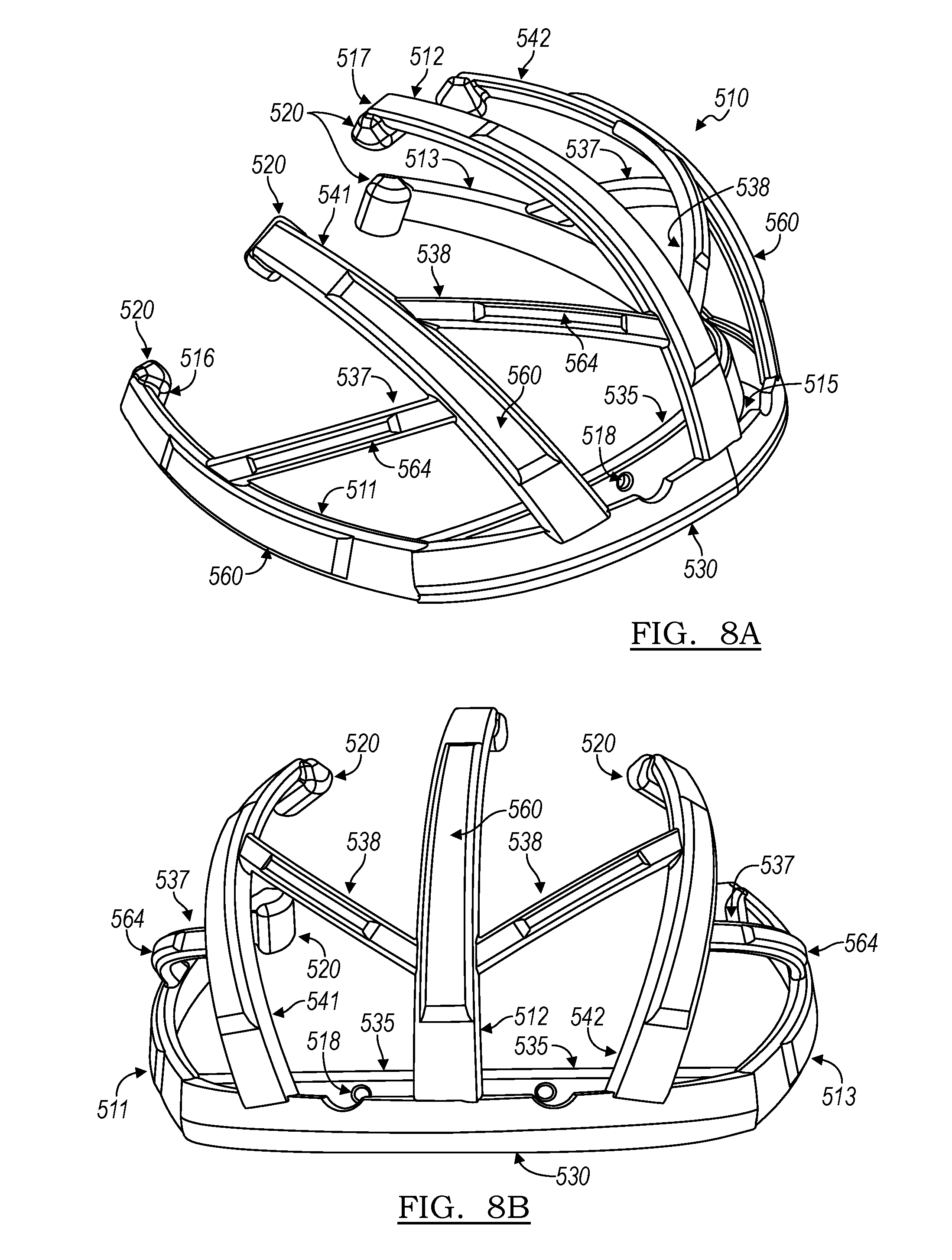
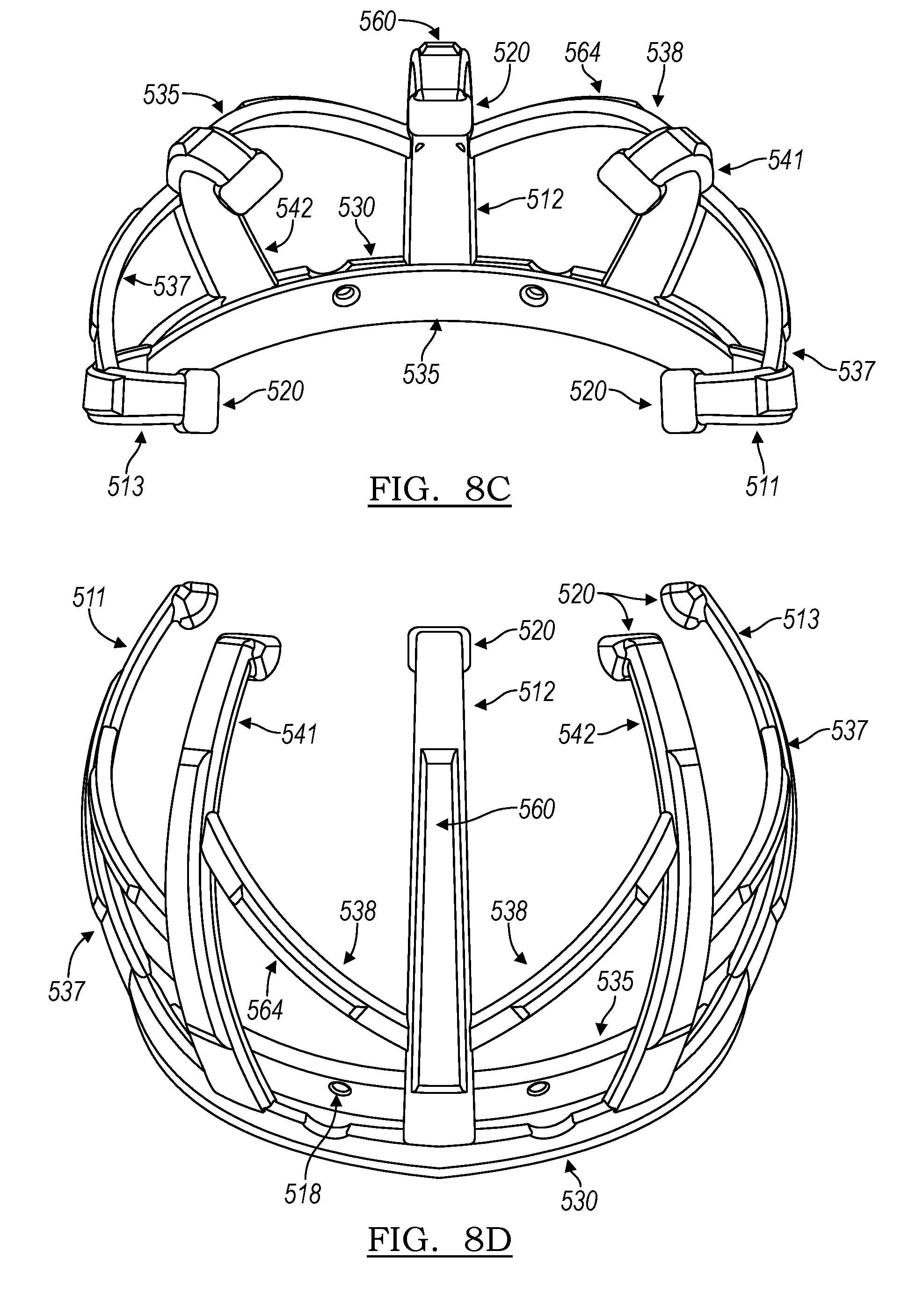
[0056] Turning to FIGS. 8A-8F, several views of a device 510 in accordance with the principles of the present disclosure are provided. The design of the device 510 is similar to that of the embodiment of FIG. 7, having five leaf springs: a central leaf spring 512 having first end (or anchored end) 515 and extending to second end 517 arcuately such that it may fit over the crown of a helmet. The central leaf spring 512 may be attached to the base 530 approximately halfway between the left end of the base 530 and the right end of the base 530. Left side leaf spring 513 and right side leaf spring 511 continue are attached to the base 530 and, together with the base 530, comprise a substantially arcuate portion which extends from at or behind the left ear, across the forehead, and ends at or behind the right ear of a wearer. Fourth leaf spring 542 is positioned substantially between, in some embodiments approximately halfway between, the center leaf spring 512 and the left leaf spring 513. Fifth leaf spring 541 is constructed in a similar manner and is attached to base 530 and positioned between the central leaf spring 512 and right leaf spring 511, in some embodiments approximately halfway between the central leaf spring 512 and right lead spring 511.
[0057] In some embodiments, base 530 may itself be a leaf spring. In such an embodiment, left and right leaf springs 513 and 511 may be considered extensions of or portions of base leaf spring 530.
[0058] First connecting members 538 extend from the central leaf spring 512 and adjacent leaf springs 541/542, and second connecting members 537 extend between right leaf spring 511 and fifth leaf spring 541, as well as between left leaf spring 513 and fourth leaf spring 542. Optionally, the leaf springs have beveled portions 560 formed on their outer surfaces, and the connecting members have beveled portions 564 on formed on their outer surface. In addition, each leaf spring may terminate in a foot 520, which may be a free end, and may slide across the surface of a helmet to which the device 510 is mounted.
[0059] In this embodiment, and as best seen in FIG. 8D, connecting portion 535 extends as a rear portion separate from the front portion of the base 530. This provides more spacing of the base away from the surface of a helmet. Connecting portion 535 has screw holes 518 formed therethrough to provide a convenient way of attaching the device 510 to a helmet, though the device may be attached via a different mechanism.
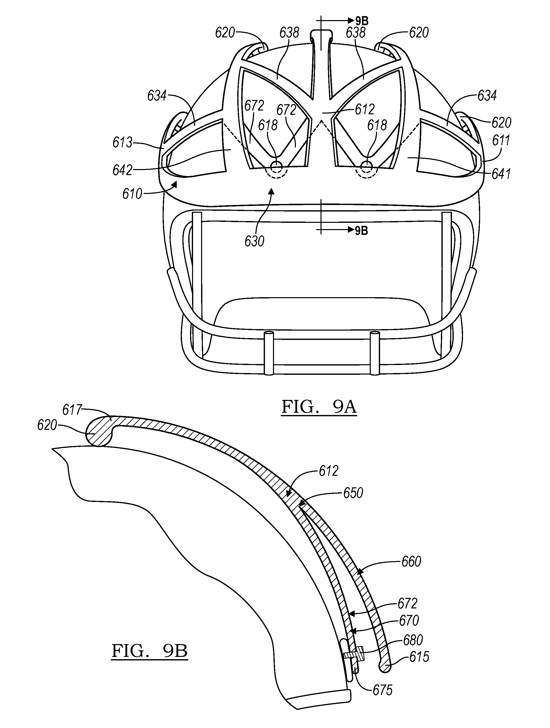
[0060] Another embodiment of an impact-mitigating device in accordance with the principles of the present description is illustrated in FIGS. 9A-9B. In this embodiment, the device 610 includes two layers of leaf springs. In the exemplary device 610 depicted in FIG. 9A, first layer (or outer layer) 660 has a similar structure to device 510 of FIG. 8A-8F, with leaf springs 611/612/613/641/642 extending from base 630, positioned at the forehead portion over the shell of the helmet, over the crown and optionally terminating in feet 620. In some embodiments, base 630 may itself be a leaf spring. In such an embodiment, left and right leaf springs 613 and 611 may be considered extensions of or portions of base leaf spring 630. Connecting portions 634/638 may optionally connect adjacent leaf springs to one another. In addition, device 610 has a second layer 670 positioned between the first layer 660 and the shell of the helmet 680 to which it may be attached. The second layer 670 is positioned adjacent to, and inward of, the first layer 660; that is, when attached to a helmet, second layer 670 is closer to the surface of the helmet than first layer 660. The second layer 670 may be unitarily constructed with first layer 660 and may include a layer of leaf springs 672 that underlie the first layer 670. The device 610 includes four leaf springs 672 in the embodiment depicted in FIG. 9A. However, in other embodiments, a single leaf spring or any other number of leaf springs may be employed.
[0061] A cross-section of the device 610 taken along line 9B of FIG. 9A is shown in FIG. 9B. The spatial arrangement of first layer 660 and second layer 670 relative to one another can be seen in this view. The first layer 660 extends from first end 615 to convergence point 650, and the second layer 670, which includes leaf springs 672, likewise extends from second end 675 to convergence point 650, at which point the leaf spring 612 becomes a single-layer portion of the device through third end 617, which may an anchored end, and foot 620, which may be a free end. The first and second layers 660/670 may be capable of motion independent of one another, or may optionally move in concert.
[0062] The second layer 670 is affixed to the helmet 680 in this embodiment via screw 682, although other ways of attaching the device 610 to the helmet 680 as described herein may be used instead. A device of this design will assist in mitigating an impact directly to the attachment point by allowing for a change in the first point of flexion from the base 630 of the device to a point substantially at the convergence point 650. Furthermore, after the leaf spring of first layer 660 bends in response to such an impact, it will contact the leaf spring of the second layer 670, which in turn will also flex, providing further mitigation of the impact. Therefore, the layering of these leaf spring structures provides an additional dimension of flexibility to the base of the device. A multilayer device as depicted in FIGS. 9A-9B can be manufactured in a number of ways, including by injection molding.
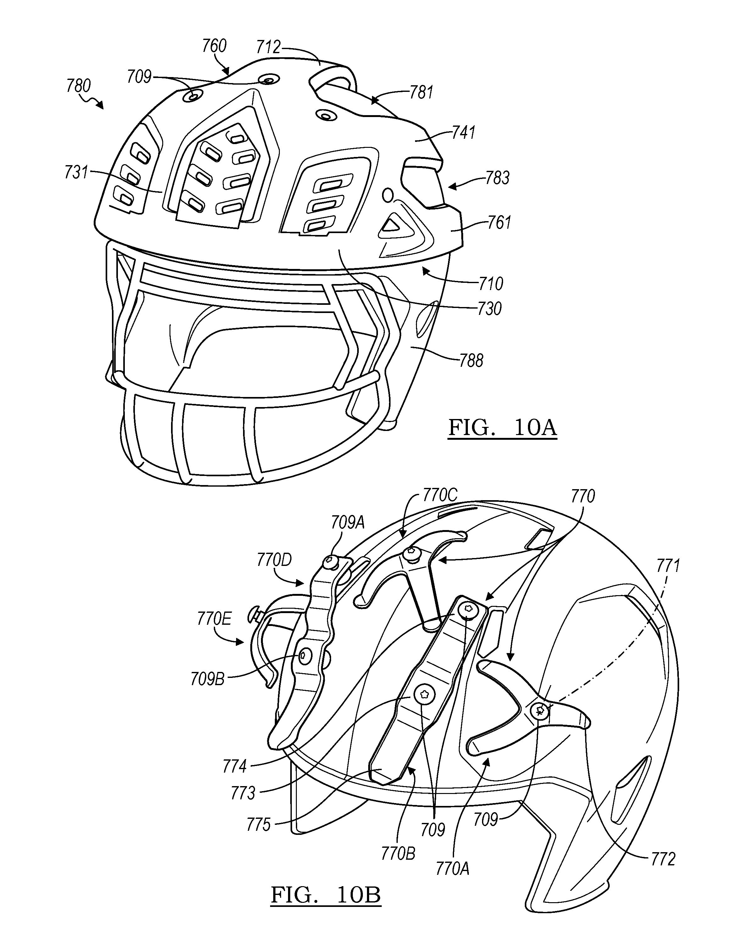
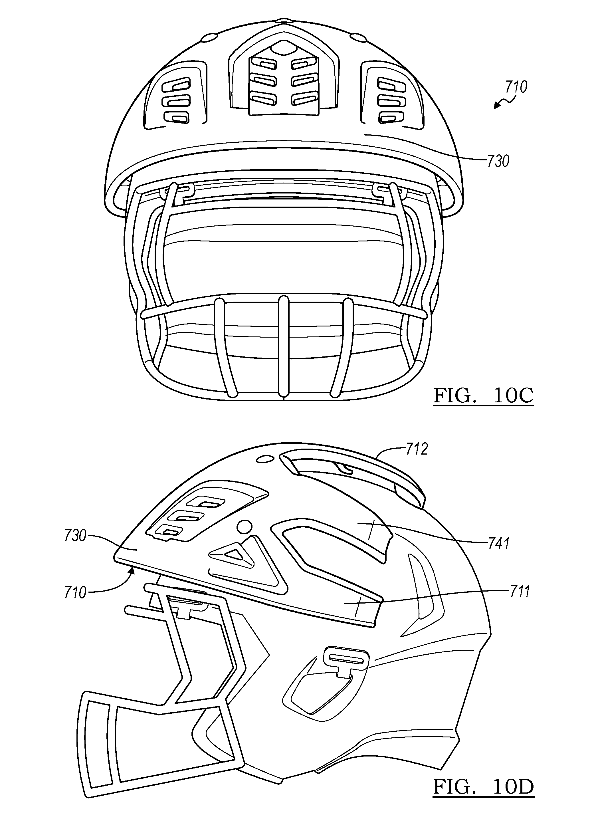
[0063] Another embodiment of an impact-mitigating device in accordance with the principles of the present description is illustrated in FIGS. 10A-10F. In this embodiment, the device 710 includes two layers of leaf springs and is coupled with a helmet 780 having a shell portion 788 for receiving a user's head. In the exemplary device 710 depicted in FIG. 10A, outer layer 760 is configured to dissipate forces. For example, the outer layer may include a base portion 730 and leaf springs 711, 712, 713, 741, 742 extending from the base 730.
[0064] The base portion 730 shown in FIG. 10A includes a shield portion 731 covering a substantial portion of the front area of the shell 788 so as to be generally aligned with the user's forehead. The base portion 730 shown in FIG. 10A also extends back towards the crown 781 and the sides 783 of the shell 788 and optionally terminating in feet 720. In the embodiment illustrated in FIGS. 10A-10F, the base portion 730 covers a significant portion of the forehead portion of the helmet and includes a relatively smooth outer surface. This configuration may promote glancing collisions between helmets and reduce the likelihood that helmets catch each other or stick together. This configuration may also reduce the likelihood that body parts, such as fingers, become caught-up in the base portion 730. The base portion 730 may also include a tapered inlay section and/or slits to reduce the weight of the device, to reduce material costs, or to reduce vibration. The leaf springs 711, 712, 713, 741, 742 each have a fixed point at the base 730 and a free end, such as feet 720 shown in FIG. 10F, that is able to move relative to the helmet 780.
[0065] The outer layer 760 shown in FIGS. 10A-10F may be removably coupled with the helmet 780 by any suitable connection, such as a snap-fit connection, a tab/slot connection, adhesive, or a plurality of fasteners 709. The fasteners 709 shown in FIG. 10A, which may be screws, removably secure the base portion 730 to the helmet 780.
[0066] The outer layer 760 may be designed such that when it is coupled with the helmet 780 and in a resting state (i.e., when no external forces are applied to the helmet) each of the leaf springs 711, 712, 713, 741, 742 is biased against the helmet 780. For example, in such a configuration, the feet 720 each contact the surface of the helmet 780 when the outer layer 760 is touching and/or applying a force against the helmet 780. Alternatively, the outer layer may be coupled with the helmet 780 such that in a resting state each of the leaf springs 711, 712, 713, 741, 742 is spaced apart from the helmet 780.
[0067] The device shown in FIG. 10B also includes an inner dissipation layer 770 configured to further dissipate forces acting on the helmet 780. The inner dissipation layer 770 shown in the figures includes five components but may alternately include any suitable number of components, including a single component. For example, the inner dissipation layer 770 shown in FIG. 10B includes five leaf springs 770A, 770B, 770C, 770D, 770E, each of which includes at least one fixed point and one or more free points configured to move relative to the helmet 780. As an example, one of the leaf springs 770A includes one fixed point 771 at or near fastener 709 and three free ends 772 that are able to move relative to the helmet 780. As another example, another of the leaf springs 770B includes two fixed points 773, 774 at or near fasteners 709 and a free end 775 that is able to move relative to the helmet 780.
[0068] As with the outer layer 760, the inner layer 770 shown in FIGS. 10A-10F may be removably coupled with the helmet 780 by any suitable connection, such as a snap-fit connection, a tab/slot connection, adhesive, or a plurality of fasteners 709. The fasteners 709 shown in FIG. 10B, which may be screws, removably secure the inner layer 760 to the helmet 780. Fasteners 709 may be used to removably secure just the inner layer 770, just the outer layer 760, or both layers 760, 770. For example, the fastener 709A shown in FIG. 10B is used to secure inner leaf spring 770D of the inner layer 770 and the outer layer 760 to the helmet 780. The fastener 709A may include a spacer to hold town the inner leaf spring 770D while also securing the outer layer 760. As another example, the fastener 709B shown in FIG. 10B is used to secure inner leaf spring 770D only.
[0069] Also as with the outer layer 760, the inner layer 770 may be designed such that when it is coupled with the helmet 780 and in a resting state (i.e., when no external forces are applied to the helmet) each of the leaf springs 770A, 770B, 770C, 770D, 770E is biased against the helmet 780. For example, in such a configuration, the free ends of the leaf springs 770A, 770B, 770C, 770D, 770E each contact the surface of the helmet 780 when the inner layer 770 is touching and/or applying a force against the helmet 780. Alternatively, the inner layer may be coupled with the helmet 780 such that in a resting state the free ends of each of the leaf springs 770A, 770B, 770C, 770D, 770E is spaced apart from the helmet 780. As another example, as shown in FIG. 10F, the inner layer leaf springs 770A, 770B, 770C, 770D, 770E may be coupled with the outer layer 760 via tabs 755. The inner and outer layers may be then selective coupled with the helmet 780.
[0070] FIG. 11 shows leaf spring 800 for dissipating forces on a curved object. A helmet 810 is shown as an exemplary curved object, but any suitable curved object may be utilized. The leaf spring 800 includes an anchor point 820 for receiving a fastener, such as the fastener 709 shown in FIG. 10A, and a free arm 830 extending away from the anchor point 820. The free arm 830 has a plurality of bend portions 840A, 840B, 840C, 840D configured to dissipate forces substantially equally along the length of the free arm 830. For example, each bend portion shown in FIG. 11 is substantially convex or substantially concave and each bend portion is generally parabolic with a particular length and general arc. These parameters, and other parameters such as width or thickness of the free arm, may be designed such as to dissipate anticipated forces substantially equally along the length of the free arm 830. For example, the leaf spring 800 is designed such that when an external force acts on the leaf spring 800 at an expected magnitude and direction, the free arm 830 experiences substantially constant stresses along the length of the free arm 830.
[0071] The leaf spring 800 shown in FIG. 11 also includes a pair of raised portions 850 adjacent to the anchor point 820. The leaf spring 800 also includes an additional free end 860 extending away from the anchor point 820 for further dissipating forces acting on the leaf spring 800.
[0072] Cross-sectional views of an embodiment of an impact mitigation device 910 are shown in FIGS. 12A, 12B, and 13. Portions of the device 910 are shaped to be spaced apart from the outer surface 987 of helmet 980 in order to allow the leaf springs (such as leaf spring 912) to flex and reduce the impact from forces. As shown in FIG. 12A, near end 999 of center leaf spring 912, the device 910 is spaced a distance 995 from outer surface 987 which may be about 13.1 millimeters (mm). Proximate the junction of the base 930 and leaf spring 912, the spacing 994 may be about 19.5 mm. Spacings between the base 930 and the outer surface 982 may, for example, include distance 993 which may be about 20.8 mm; distance 992 which may be about 18.5 mm; and distance 991 at a position 990 near the end of the base 930, which may be about 35.3 mm.
[0073] FIG. 12B is a cross section of the device 910 and helmet 980 which illustrates spacings between side leaf springs 911/913 and the outer surface 987, as well as between the base 930 and the outer surface 987. These include distance 986, near end 995 of leaf spring 913, which may be about 12.0 mm; distance 985, which may be about 15.3 mm; distance 984, which may be about 15.0 mm near the junction of the base 930 and leaf spring 913; distance 983 between the vase 930 and outer surface 987, which may be about 26.6 mm; distance 982, which may be about 33.3 mm; and distance 981, which may be about 34.6 mm.
[0074] Besides the fixed contact points between the device 910 and the helmet 980, the spacing between the device 910 and the outer surface 982 of helmet 980 may vary from about 5 mm to about 40 mm, or from about 10 mm to about 37 mm, at various positions. In other embodiments, the spacing may be between 0 mm and 5 mm, or greater than 40 mm.
[0075] As illustrated in FIG. 13, these spacings allow the device 910 to shift and rotate in response to externally-applied forces. For example, contact may cause the device 910 to rotate forward according to motion 996, rather than be compressed downward 998, permitting less force to be transmitted to the helmet 980 and thus the skull of the user. Such contact may be accompanied by a slight shift 997 back toward the helmet 980 by base 930, without contact between the two.
[0076] FIG. 14 illustrates that an impact mitigation device 1010 may be attached to a helmet 1080 by a strap assembly 1075. Such an assembly may include a plurality of straps to secure the device 1010, with hooks to keep the straps attached to the helmet 1080. For example, in FIG. 14, hook 1077 engages earhole 1081 of helmet 1080, as the strap runs under the device and around the back of the helmet, reattaching under the device on the opposite side (not shown.) Optionally, there may be attachment points for a strap on the back of the helmet as well. The strap assembly 1075 may optional include multiple straps, such as strap 1073 which runs along the crown of the helmet, through space 1071 between leaf springs 1012 and 1042, and under the device to secure the device 1010 to the helmet 1080. In some embodiments, the use of the strap may obviate the need for other hardware, such as screws or nuts and bolts. In other embodiments, some or all of this hardware may be retained in addition to the strap.
[0077] In another embodiment, as illustrated in FIGS. 15A-15D, an impact mitigation device 1110 may include an alternative type of inner dissipation layer. The device 1110 may be a plastic or composite device, monolithically formed, with leaf springs 1111/1112/1113/1141/1142 as described in other embodiments and is further provided with an inner dissipation layer 1167 which is a foam layer disposed on the leaf springs and on the base 1130. The inner dissipation later 1167 may be in direct contact with the helmet 1180, and may prevent direct contact between the leaf springs of device 1110 and the helmet 1180 in some embodiments. In other embodiments, contact between the leaf springs and the helmet 1180 is still possible. In some embodiments, only the base may be provided with an inner dissipation layer; in other embodiments, only the leaf springs are provided with an inner dissipation layer. In still other embodiments, both the leaf springs and the base are provided with an inner dissipation layer.
[0078] As shown in FIG. 15A, the inner dissipation layer 1167 may be one of several inner dissipation layers. In the illustrated embodiment, inner dissipation layer 1167 may be located beneath inner dissipation layer 1168, which is located beneath inner dissipation layer 1169, which is attached directly to the body of device 1110. The materials used in inner dissipation layer 1167 may be made from the same, or different materials as, the layers 1168 and 1169. The three inner dissipation layers 1167, 1168, 1169 may have the same or different densities or other properties. In the illustrated embodiment, inner dissipation layer 1167 is a foam layer made of a high-density, closed-cell foam, approximately one-half inch thick. In the depicted embodiment, inner dissipation layer 1168 and inner dissipation layer 1169 are made of polyvinyl chloride (PVC) which is approximately 5 millimeters thick. Materials of the inner dissipation layers may be selected from a rubber, a polymer foam, rubberized plastics, closed-cell foams, open-cell foams, or any other suitable material known in the art. A foam may be well-suited for this application as it may dampen a blow received by the device 1110, and after deformation it may return to its original shape. An inner dissipation layer 1167 may be employed in a metal device or in a plastic or composite device, but may be better suited to a plastic/composite device in order to slow the depression of the device 1110 upon impact. Any number of inner dissipation layers is acceptable for use in constructing the device 1110, which will be apparent to a person of skill in the art. In some embodiments, it may be acceptable for a gap 1166 between the inner dissipation layer 1167 and the helmet 1180 to be present.
[0079] As shown in FIG. 15B, the amount of coverage of the interior of device 1110 by inner dissipation layers may vary. The device 1110 of FIG. 15B is covered with foam. A thinner layer 1061 of foam is distributed over the leaf springs 1111/1112/1113/1141/1142, with a thicker layer 1063 being disposed at the forehead and temple region, on base 1130. As may best be seen in FIGS. 15B and 15D, gaps 1164 may be present between portions 1163 where the thicker foam lies. As illustrated in FIG. 15D, the inner dissipation layer may include a plurality of thinner zones 1161, such as for example on the leaf springs, and a plurality of thicker zones 1163, such as on the base. In one embodiment, the thicker zones 1063 may be from about 20 mm to about 40 mm thick, or from about 25 mm to about 35 mm thick, or about 30 mm thick, whereas the thinner zones 1061 may be from about 5 mm thick to about 25 mm thick, or about 10 mm thick to about 22.5 mm thick, or about 15 mm thick to about 20 mm thick, or about 20 mm thick.
[0080] In the device shown in the drawings, the inner layer is made of metal and the outer layer is made of a composite material, but any suitable materials may be used. In another embodiment, the leaf spring and base portion of the device may be made of plastic or a composite material throughout. When selecting materials, shape, size, thickness, curvature, and other suitable parameters, one may consider any or all of the following factors: weight of device, modulus of elasticity of materials, length of the leaf springs, thickness of the leaf spring, expected forces applied to the leaf springs, location and direction of expected forces applied to the leaf springs. One may utilize computer modeling and/or finite element analysis when designing parameters of the device.
[0081] The positioning of the impact-mitigating device can be tailored to specific applications as desired. In the case of a football helmet, which has an exterior generally made up of the protective shell portion (surrounding the cranium) and the facemask (positioned over the face), attachment to either the shell, the facemask, or both, is contemplated. Moreover, the device could be fixed at the front of the helmet, as shown in a variety of illustrations included herewith, or in the back of the helmet, or on at least one side of the helmet, or any combination thereof. The length of the leaf springs could be such that they cover a portion of or the entirety of the helmet in any dimension.
[0082] It is noted that the principles of the present disclosure will find uses beyond football, and indeed beyond sports. Other sports where head injuries have become a pressing concern include but not limited to lacrosse, ice hockey, field hockey, skiing, snowboarding, cycling, skateboarding, rollerblading, and motorsports including snowmobiling and the use of all-terrain vehicles (or four-wheeling). In all of these sports and recreational activities there is a danger of contact with other players, the environment, or equipment which could case immediate or long term head injuries. Other activities where head injuries occur such as construction worksites and military training and combat activities are also coming under more scrutiny to protect participants.
[0083] In these embodiments it may be advantageous to form the entire device unitarily by any suitable technique. In one embodiment, a plastic device or a metal device in accordance with the principles of this disclosure may be cast as in a mold. In another embodiment such a device may be created by an additive manufacturing process, such as 3D printing. These examples are not intended to be limiting.
[0084] Devices of this construction have numerous further advantages which make them both effective and suitable for use in the context of any level of football, or other head injury prone activity. For instance, if a sports league does not adopt a force mitigation device for use in official games, but a player wishes to derive the benefit of less force to the head during practices, the device can be easily removed from the helmet by removing the two screws that attach it to the helmet. Therefore the same helmet, which is adapted to fit the player securely and individually, can be used for practices and for games.
[0085] Aesthetically, the device of the present disclosure is thought to be capable of working in the context of any sports league, worksite or other time a helmet is or could be worn. To keep disruptions of design elements to a minimum, the device may be formed as part of the helmet or add on of an appropriately-colored plastic or polymer, or, if made of metal or other material, the device can be painted to fit the color scheme of the particular team which will be using it. In another embodiment, the device may be made of a transparent resilient plastic so that there is no disruption to the design of a helmet at all. In a further embodiment, to maintain the aesthetics specified by a team, a nylon or similar fabric shell may be stretched over the device to provide a uniform appearance.
[0086] While the present invention has been described in terms of preferred embodiments, it will be understood, of course, that the invention is not limited thereto since modifications may be made to those skilled in the art, particularly in light of the foregoing teachings.
* * * * *
D00000
D00001
D00002
D00003
D00004
D00005
D00006
D00007
D00008
D00009
D00010
D00011
D00012

D00013

D00014

D00015

D00016

D00017

XML
uspto.report is an independent third-party trademark research tool that is not affiliated, endorsed, or sponsored by the United States Patent and Trademark Office (USPTO) or any other governmental organization. The information provided by uspto.report is based on publicly available data at the time of writing and is intended for informational purposes only.
While we strive to provide accurate and up-to-date information, we do not guarantee the accuracy, completeness, reliability, or suitability of the information displayed on this site. The use of this site is at your own risk. Any reliance you place on such information is therefore strictly at your own risk.
All official trademark data, including owner information, should be verified by visiting the official USPTO website at www.uspto.gov. This site is not intended to replace professional legal advice and should not be used as a substitute for consulting with a legal professional who is knowledgeable about trademark law.