Method And System For User Plane Traffic Characteristics And Network Security
ALFANO; Nicholas Patrick ; et al.
U.S. patent application number 15/692836 was filed with the patent office on 2019-02-28 for method and system for user plane traffic characteristics and network security. The applicant listed for this patent is BlackBerry Limited. Invention is credited to Nicholas Patrick ALFANO, Axel FERRAZZINI, Dake HE.
| Application Number | 20190068625 15/692836 |
| Document ID | / |
| Family ID | 65437982 |
| Filed Date | 2019-02-28 |

View All Diagrams
| United States Patent Application | 20190068625 |
| Kind Code | A1 |
| ALFANO; Nicholas Patrick ; et al. | February 28, 2019 |
METHOD AND SYSTEM FOR USER PLANE TRAFFIC CHARACTERISTICS AND NETWORK SECURITY
Abstract
A method at a network element for monitoring user plane traffic for a user equipment, the method including configuring a set of characteristics and a range of values for each of the set of characteristics for user plane traffic between the user equipment and the network element; monitoring user plane traffic for the user equipment at the network element, the monitoring determining whether at least one characteristic of the user plane traffic falls outside of the configured range of a values, resulting in a characteristic violation; and if the at least one characteristic of the user plane traffic falls outside the configured range of a values, performing an action resulting from the characteristic violation.
| Inventors: | ALFANO; Nicholas Patrick; (Vancouver, CA) ; FERRAZZINI; Axel; (Uccle, BE) ; HE; Dake; (Waterloo, CA) | ||||||||||
| Applicant: |
|
||||||||||
|---|---|---|---|---|---|---|---|---|---|---|---|
| Family ID: | 65437982 | ||||||||||
| Appl. No.: | 15/692836 | ||||||||||
| Filed: | August 31, 2017 |
| Current U.S. Class: | 1/1 |
| Current CPC Class: | H04L 43/0876 20130101; H04W 12/005 20190101; H04L 43/16 20130101; H04L 63/1425 20130101; H04L 63/1408 20130101; H04L 67/22 20130101; H04W 12/0013 20190101; H04W 12/12 20130101; H04L 43/062 20130101; H04L 41/069 20130101; H04L 63/0263 20130101; H04L 63/20 20130101 |
| International Class: | H04L 29/06 20060101 H04L029/06; H04L 29/08 20060101 H04L029/08; H04L 12/24 20060101 H04L012/24; H04L 12/26 20060101 H04L012/26 |
Claims
1. A method at a network element for monitoring user plane traffic for a user equipment, the method comprising: configuring a set of characteristics and a range of values for each of the set of characteristics for user plane traffic between the user equipment and the network element; monitoring user plane traffic for the user equipment at the network element, the monitoring determining whether at least one characteristic of the user plane traffic falls outside of the configured range of a values, resulting in a characteristic violation; and if the at least one characteristic of the user plane traffic falls outside the configured range of a values, performing an action resulting from the characteristic violation.
2. The method of claim 1, wherein the user plane traffic is transmitted without at least one of integrity and encryption protection.
3. The method of claim 1, wherein the set of characteristics include at least one characteristic selected from the group comprising: the user equipment location; traffic volume to or from the user equipment; time of day for traffic for the user equipment; number of connections to the user equipment; duration of a session at the user equipment; a maximum number of data packets sent during a time period from the user equipment; a datatype for packets from the user equipment; a destination address for packets from the user equipment; and a permitted subscription usage for the user equipment.
4. The method of claim 1, wherein the configuring is performed during an ATTACH procedure between the user equipment and the network element.
5. The method of claim 1, wherein the action comprises triggering alarms in a public land mobile network, network management function.
6. The method of claim 1, wherein the action comprises triggering a secure message to the user equipment containing information associated with the characteristic violation.
7. The method of claim 1, wherein the action comprises dropping packets to or from the user equipment.
8. The method of claim 1, wherein the action comprises performing a connection re-establishment by performing DETACH procedure on the user equipment and further by performing an ATTACH procedure from the user equipment.
9. The method of claim 1, wherein the action triggers an authentication procedure for the user equipment.
10. The method of claim 2, wherein the action comprises turning on at least one of encryption or integrity protection.
11. A network element for monitoring user plane traffic for a user equipment, the network element comprising: a processor; and a communications subsystem, wherein the network element is configured to: configure a set of characteristics and a range of values for each of the set of characteristics for user plane traffic between the user equipment and the network element; monitor user plane traffic for the user equipment at the network element, the monitoring determining whether at least one characteristic of the user plane traffic falls outside of the configured range of a values, resulting in a characteristic violation; and if the at least one characteristic of the user plane traffic falls outside the configured range of a values, perform an action resulting from the characteristic violation.
12. The network element of claim 11, wherein the user plane traffic is transmitted without integrity or encryption protection.
13. The network element of claim 11, wherein the set of characteristics include at least one characteristic selected from the group comprising: the user equipment location; traffic volume to or from the user equipment; time of day for traffic for the user equipment; number of connections to the user equipment; duration of a session at the user equipment; a maximum number of data packets sent during a time period from the user equipment; a datatype for packets from the user equipment; a destination address for packets from the user equipment; and a permitted subscription usage for the user equipment.
14. The network element of claim 11, wherein the network element is configured to configure the set of characteristics during an ATTACH procedure between the user equipment and the network element.
15. The network element of claim 11, wherein the action comprises triggering alarms in a public land mobile network, network management function.
16. The network element of claim 11, wherein the action comprises triggering a secure message to the user equipment containing information associated with the characteristic violation.
17. The network element of claim 11, wherein the action comprises dropping packets to or from the user equipment.
18. The network element of claim 11, wherein the action comprises performing a connection re-establishment by performing DETACH procedure on the user equipment and further by performing an ATTACH procedure from the user equipment.
19. The network element of claim 11, wherein the action triggers an authentication procedure for the user equipment.
20. The network element of claim 2, wherein the action comprises turning on at least one of encryption or integrity protection.
21. A computer readable medium for storing program instructions for monitoring user plane traffic for a user equipment, which when executed by a processor of a network element cause the network element to: configure a set of characteristics and a range of values for each of the set of characteristics for user plane traffic between the user equipment and the network element; monitor user plane traffic for the user equipment at the network element, the monitoring determining whether at least one characteristic of the user plane traffic falls outside of the configured range of a values, resulting in a characteristic violation; and if the at least one characteristic of the user plane traffic falls outside the configured range of a values, perform an action resulting from the characteristic violation.
Description
FIELD OF THE DISCLOSURE
[0001] The present disclosure relates to user plane communications in a mobile network, and in particular relates to network security with regards to user plane communications.
BACKGROUND
[0002] Integrity and confidentiality of traffic between a User Equipment (UE) and Network may create a cost for processing power, and may also reduce the battery life, at a UE. Operating with no security may enable the deployment of devices with longer battery life and less processing power.
[0003] However, sending unprotected communications over the air can introduce security risks to the network and to the UE, including but not limited to eavesdropping; originator spoofing; injection of invalid data; or denial of service (DoS) attacks.
[0004] Unprotected connections may allow for possible corruption of the data on route, which may have an impact on the network infrastructure or performance.
[0005] Due to such risks, network operators are hesitant to allow connections to their network that are unprotected.
BRIEF DESCRIPTION OF THE DRAWINGS
[0006] The present disclosure will be better understood with reference to the drawings, in which:
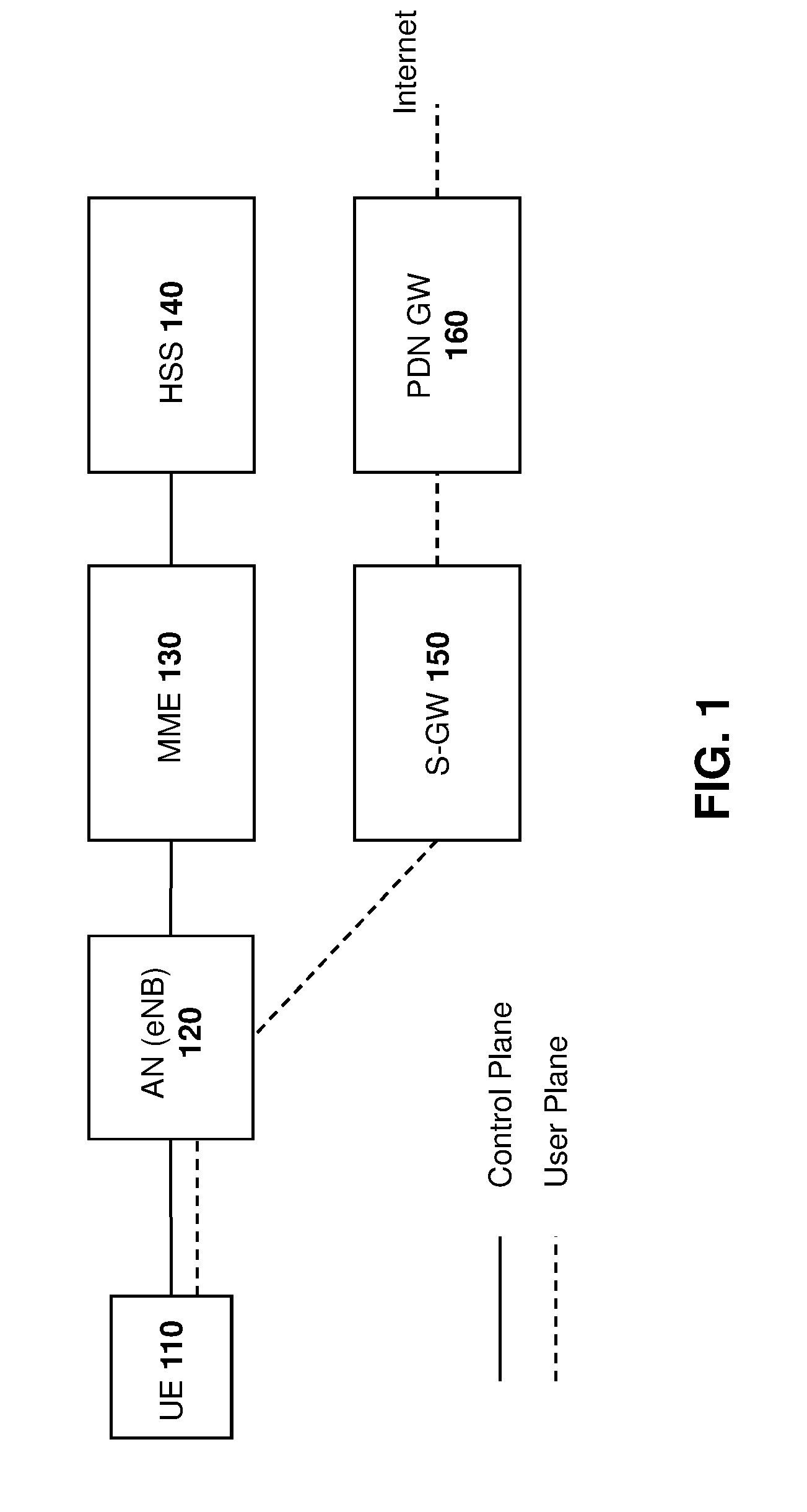
[0007] FIG. 1 is a block diagram showing an example evolved packet core network architecture;
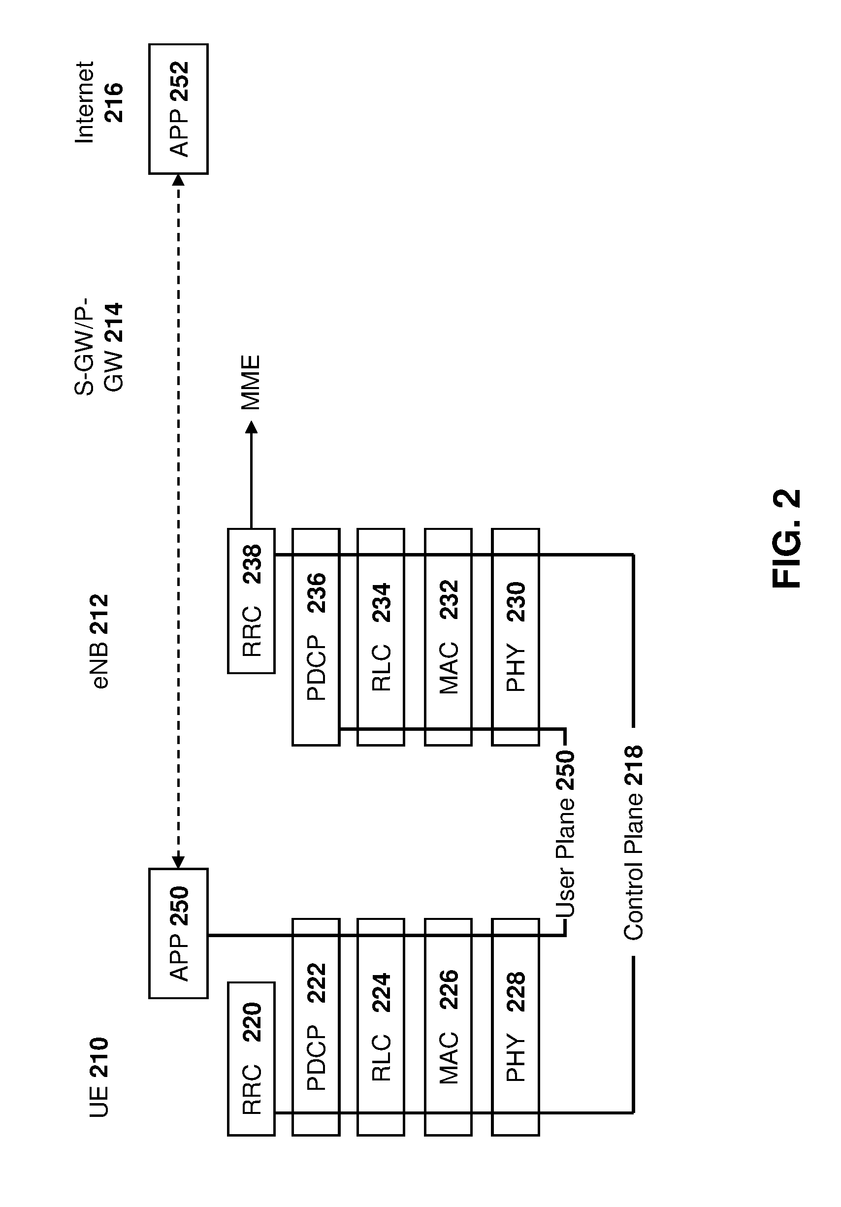
[0008] FIG. 2 is a block diagram showing user plane confidentiality as provided by the packet data control protocol layer in the evolved packet core;
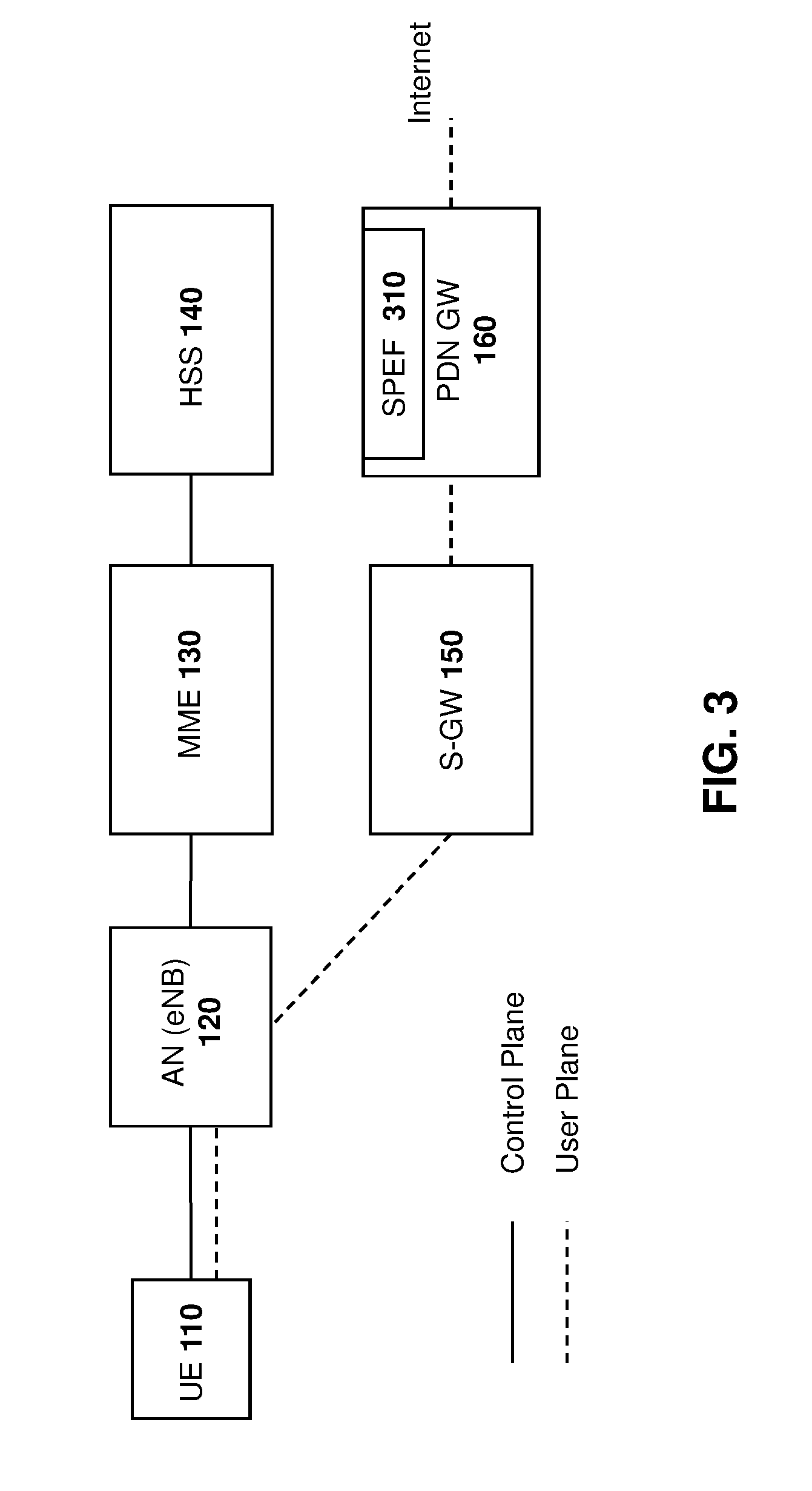
[0009] FIG. 3 is a block diagram showing an example evolved packet core network architecture having a security policy enforcement function added to the packet data network gateway;
[0010] FIG. 4 is a block diagram showing an example fifth generation network architecture having a security policy enforcement function added to the user plane function;
[0011] FIG. 5 is a dataflow diagram showing configuration of characteristics and parameters at the user plane function;
[0012] FIG. 6 is a dataflow diagram showing an example ATTACH procedure;
[0013] FIG. 7 is a process diagram showing a process for monitoring packet data to determine whether a cumulative amount of data over a time period exceeds a parameter threshold;
[0014] FIG. 8 is a process diagram showing a process for monitoring packet data to determine a location of a user equipment;
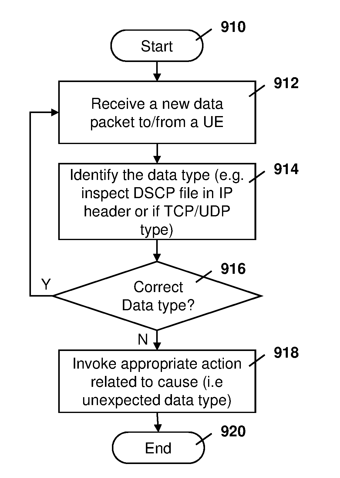
[0015] FIG. 9 is a process diagram showing a process for monitoring a packet data type to ensure an expected packet data type is being conveyed by a network;
[0016] FIG. 10 is a dataflow diagram for updating a policy on detection of an anomaly;
[0017] FIG. 11 is a dataflow diagram showing the sending of a secure message to a user equipment indicating that an anomaly has been detected;
[0018] FIG. 12 is a dataflow diagram showing the dropping of user plane packets upon detection of an anomaly and further optionally releasing an RRC Connection with the user equipment;
[0019] FIG. 13 is a dataflow diagram showing the initiation of a counter check procedure upon detection of an anomaly;
[0020] FIG. 14 is a dataflow diagram showing the initiation of an authentication request with a user equipment upon detection of an anomaly;
[0021] FIG. 15 is a dataflow diagram showing a DETACH procedure upon detection of an anomaly;
[0022] FIG. 16 is a dataflow diagram showing RRC RECONFIGURATION of a user equipment to turn on encryption and/or integrity detection upon detection of an anomaly;
[0023] FIG. 17 is a dataflow diagram showing an example DETACH procedure;
[0024] FIG. 18 is a block diagram showing a simplified computing device capable of being used with the method and embodiments of the present disclosure; and
[0025] FIG. 19 is a block diagram of an example user equipment capable of being used with the methods and embodiments of the present disclosure.
DETAILED DESCRIPTION OF THE DRAWINGS
[0026] The present disclosure provides a method at a network element for monitoring user plane traffic for a user equipment, the method comprising: configuring a set of characteristics and a range of values for each of the set of characteristics for user plane traffic between the user equipment and the network element; monitoring user plane traffic for the user equipment at the network element, the monitoring determining whether at least one characteristic of the user plane traffic falls outside of the configured range of a values, resulting in a characteristic violation; and if the at least one characteristic of the user plane traffic falls outside the configured range of a values, performing an action resulting from the characteristic violation.
[0027] The present disclosure further provides a network element for monitoring user plane traffic for a user equipment, the network element comprising: a processor; and a communications subsystem, wherein the network element is configured to: configure a set of characteristics and a range of values for each of the set of characteristics for user plane traffic between the user equipment and the network element; monitor user plane traffic for the user equipment at the network element, the monitoring determining whether at least one characteristic of the user plane traffic falls outside of the configured range of a values, resulting in a characteristic violation; and if the at least one characteristic of the user plane traffic falls outside the configured range of a values, perform an action resulting from the characteristic violation.
[0028] The present disclosure further provides a computer readable medium for storing program instructions for monitoring user plane traffic for a user equipment, which when executed by a processor of a network element cause the network element to: configure a set of characteristics and a range of values for each of the set of characteristics for user plane traffic between the user equipment and the network element; monitor user plane traffic for the user equipment at the network element, the monitoring determining whether at least one characteristic of the user plane traffic falls outside of the configured range of a values, resulting in a characteristic violation; and if the at least one characteristic of the user plane traffic falls outside the configured range of a values, perform an action resulting from the characteristic violation.
[0029] A wide array of user equipment (UE) types will use fifth generation (5G), or beyond, services. Such UEs may include Internet of Things (IoT) devices, some of which may have very limited processing power and memory. As such, a one size fits all security mechanism will not serve all device types well and can be quite costly relative to the market for which the device is targeted.
[0030] Therefore, in accordance with the embodiments below, there is provided a mechanism primarily designed to support IoT devices connecting to wide-area cellular networks, where the security overheads for transmission are reduced, typically resulting in lower processing power requirements and longer battery life for the device.
[0031] While the embodiments described below are provided for 5G networks and devices, in some cases the solutions provided could be used with fourth generation networks or could be used with future networks beyond 5G. The present disclosure is therefore not limited to 5G networks and devices.
[0032] Reference is now made to FIG. 1, which shows an example Evolved Packet Core network in a 4G network. In the embodiment of FIG. 1, a UE 110 communicates over the network using an Access Node (AN) 120. The AN 120 is typically an evolved Node B (eNB).
[0033] AN 120 communicates with an Evolved Packet Core (EPC), which in part comprises a Mobility Management Entity (MME) 130, Home Subscriber Server (HSS) 140, Serving Gateway (S-GW) 150 and Packet Data Network (PDN) Gateway (P-GW) 160.
[0034] MME 130 controls operation of device 110 through signaling messages using HSS 140.
[0035] S-GW 150 acts as a router and forwards data to the P-GW 170 over an S5/S8 interface.
[0036] P-GW 160 provides the interface between the 4G network and other networks such as the Internet or private networks. P-GW 160 is connected to a public data network PDN over an SGi interface.
[0037] Those skilled in art will appreciate that wireless network may be connected to other systems, possibly including other networks, not explicitly shown in FIG. 1.
[0038] In the embodiment of FIG. 1, control plane traffic flows between the UE 110, AN 120, MME 130 and HSS 140.
[0039] Further, user plane traffic flows between UE 110, AN 120, SGW 150 and P-GW 160.
[0040] Specifically, reference is made to FIG. 2, which shows communications between the various layers at the UE 210 and eNB 212.
[0041] In particular, for control plane traffic 218, communication from the UE proceeds from the Radio Resource Control (RRC) layer 220, through the Packed Data Convergence Protocol (PDCP) layer 222, Radio Link Control (RLC) layer 224, Message Authentication Control (MAC) layer 226 and to the Physical (PHY) layer 228.
[0042] Similarly, at the eNB 212, the control plane data from the UE 210 proceeds through a PHY layer 230, MAC layer 232, RLC layer 234, PDCP layer 236 and to RRC layer 238. It may then flow to the MME.
[0043] For user plane traffic 240, the traffic flows to and from an application (APP) layer 250 at UE 210. The traffic may flow through PDCP layer 222, RLC layer 224, MAC layer 226 and to PHY layer 228.
[0044] At the eNB 212, the traffic flows through PHY layer 230, MAC layer 232, RLC layer 234 to PDCP 236. It may then be forwarded through the S-GW/P-GW 214 to the Internet 216. At a server reached through Internet 216, an application layer 252 may receive the user plane traffic 250.
[0045] In 5G networks, there will likely be numerous options for a UE to select the type of service it wishes to receive from a network. One element of the options that can be negotiated between the UE and a network may be the type of security that is applied to the service. These security features, possibly occurring at the radio bearer interface between the UE and a next Generation Node B (gNB) might be, for example, the use or non-use of integrity protection, the use or non-use of confidentiality (encryption), the selection of integrity algorithm and the selection of encryption algorithm.
[0046] The security applied to the UE to Network connection may be based at least in part around the mutual authentication of the UE device and UE user to verify they are who they claim to be and have permission to access the network. This part of the connection security is called mutual authentication. The protection of the communications exchanged between the UE and Network from manipulation or spoofing is referred to as integrity. Integrity may primarily be achieved using, for example, keyed hashes or signatures. The protection of the communications between the UE and Network from eavesdropping is referred to as confidentiality. Confidentiality may be primarily achieved using, for example, encryption. Confidentiality and integrity are the two basic components which when combined provide a highly secure communications link from source to destination.
[0047] In Long Term Evolution (LTE), also referred to 4G, and 5G networks integrity and confidentiality operation over the radio interface (over-the-air) are defined for the Control Plane and User Plane traffic to ensure the security of communications across this interface. Table 1 below shows the defined options for application of integrity and confidentiality in 4G and 5G.
TABLE-US-00001 TABLE 1 UE to Network security configurations for 4G and 5G Technology/ Control Plane User Plane Traffic (UE-Network) (UE-Network) Type Integrity Confidentiality Integrity Confidentiality 4G Mandatory Optional* Forbidden Optional 5G Mandatory Optional* Optional Optional Notes *Confidentiality is recommended
[0048] In the example of Table 1, integrity ensures the UE is the expected entity, and confidentiality indicates that the communications are encrypted to prevent eavesdroppers from reading the communication.
[0049] 4G confidentiality and integrity is for example provided for in the Third Generation Partnership Project (3GPP) Technical Specification (TS) 33.401, "3GPP System Architecture Evolution (SAE); Security architecture", for example as provided in v. 15.0.0, June 2017. In particular, clause 5.1.4.1 provides for such integrity and confidentiality. Sections of 3GPP TS 33.401 are reproduced in Appendix A below.
[0050] 5G confidentiality and integrity is for example provided for in 3GPP TS 33.501, "Security architecture and procedures for 5G System", for example as provided in v. 0.2.0, June 2017. Further, 3GPP Technical Report (TR) 33.899, "Study on the security aspects of the next generation system" also provides for such confidentiality and integrity.
[0051] In current 3GPP networks, including second generation (2G), third generation (3G) and LTE, integrity and confidentiality protection is achieved by use of a shared key (K) between the UE and Network. For example, authentication details for an Enhanced Packet System (EPS) are found in 3GPP TS 33.401, section 6.1, reproduced in Appendix B of the present disclosure.
[0052] Generally, the security applied to a UE to Network radio connection is the strongest security that can be supported mutually by the UE and Network equipment. In particular, the Network would attempt to use the strongest security possible to offer protection to the UE as well as protect the network equipment from attack.
[0053] User Plane confidentiality is provided by encryption at the PDCP layer 222 or 236. It is at the PDCP layer 222 or 236 where the use or non-use of confidentiality for the User Plane is realized. The decision to configure the PDCP layer to use or not use confidentiality may be made at the RRC layer 238 (in the eNB 212) or some other equipment, possibly the MME. The PDCP layer 222 or 236 supports User Data integrity using MAC, where each message arriving at the PDCP layer would be integrity protected.
[0054] Typically, higher layer protocols (above the PDCP layer) apply security to the communication transmission, although this is not necessary in order for the embodiments of the present disclosure. The higher layer security could be for example Transport Layer Security (TLS) or Datagram TLS (DTLS), Secure Socket Layer (SSL), Hypertext Transfer Protocol Secure (HTTPS), and Internet Protocol Security (IPSec). Further, if security at the higher layers is not applied then the embodiments of the present disclosure could be used to provide improved security to those unprotected transmissions.
[0055] Based on the above, the security impact on the network infrastructure and user data traffic based on the selection of the optional aspects of the User Plane usage of integrity and confidentiality shown in Table 1 are addressed by the embodiments described below.
[0056] 3GPP TR 23.799, "Study on Architecture for Next Generation System", at clause 5.10: Policy Framework, states; [0057] In the EPC system, network functions are configurable via operator policies. This trend is expected to continue into the Next Generation System. These operator policies help shape a variety of network behaviors such as related to: [0058] Quality of Service (QoS) Enforcement. [0059] Charging Control. [0060] Gating. [0061] Traffic Routing. [0062] Congestion Management. [0063] Service Chaining. [0064] Network (e.g. PLMN) Selection. [0065] Access Type Selection. [0066] Roaming. [0067] Mobility. [0068] Policies related to group of users. [0069] Third party service handling. [0070] The provisioning and enforcement of these policies can happen in: [0071] UE. [0072] Control Plane entities. [0073] User Plane entities.
[0074] Therefore, in some cases, the embodiments of the present disclosure may be part of the Policy Framework for 5G by providing oversight on the traffic characteristics of a UE.
[0075] The present disclosure provides a network operator with more information about the use of a network service by a UE. Provided the observed transmissions comply with the described behavior of a UE, the network operator should have confidence the traffic from the UE has not been modified on-route or that the UE has not been tampered.
[0076] Specifically, good security is the combination of integrity and confidentiality on a data stream. Removing one or the other or both impacts aspects of security.
[0077] For example, integrity can protect the receiver from the tampering of the data payload, since the data payload or a portion of it is used to generate the integrity signature. Integrity can also protect against DoS attacks as additional or duplicated packets arriving at a destination would not pass the Integrity check. Integrity also ensures the connection was not hijacked by an attacker spoofing as the true originator/user of the data connection.
[0078] Confidentiality protects the data from eavesdropping and can provide some tampering protection. For example, a packet that failed the Confidentiality check because the data payload had been changed could be discarded.
[0079] Table 2 below illustrates a combination of security features and how they can protect against or expose a vulnerability. Tampering includes both the data payload and/or the Protocol Control Information (PCI or packet metadata). When confidentiality is disabled and it is not applied at a higher layer, all PCI is exposed, including critical information such as source and destination Internet Protocol (IP) address.
TABLE-US-00002 TABLE 2 Impact of Security Options on Over the Air Security Security Eaves- Denial of feature/Vulnerability dropping Tampering Service Integrity ON; Secure Secure Secure Confidentiality ON Integrity ON; Exposed Risk (user Risk ? Confidentiality OFF data) Integrity OFF; Secure Risk (meta Exposed Confidentiality ON data) Integrity OFF; Exposed Exposed Exposed Confidentiality OFF
[0080] Certain types of devices, particularly those employed in IoT type applications, may not require a great amount of security protection if the data they are exchanging is of low value. This can be the case for many IoT types of devices, where the cost of the device and its lifetime in service are larger issues than the value of an individual data exchange. Some examples of data and application that may have low value include: [0081] Metering data (parking meters) [0082] Weather data collection [0083] Some home monitoring applications (in-house temperature) [0084] Location tracking of slow moving objects (log boom)
[0085] These devices would normally be running a specific application which connects to only one destination and may also operate a security protocol at a higher layer or in the application itself. Therefore, radio layer security may be an additional, unnecessary cost.
[0086] For 5G, integrity protection for user data is optional at the radio layer. Therefore it is possible to have a user data session between UE and eNB operating with no integrity and no confidentiality protection.
[0087] Therefore, the present disclosure addresses the problem where low cost devices with minimal built-in security functions supporting integrity and confidentiality can be allowed to connect to a Public Land Mobile Network (PLMN) and not introduce security risks to the network infrastructure or other network users. It specifically addresses the scenario where no security (integrity off, confidentiality off) is applied to the OTA transmissions. The security issues addressed by the present disclosure apply to the user plane and include tampering, misuse of the connection, and denial of service attacks.
[0088] The embodiments described herein also can be used for other security benefits that are outside the scope of the UE to Network radio interface. The parameters configured in the embodiments of the present disclosure can observe device and application characteristics such as data transmission frequency, data volume, and device location (geo-fencing), data source and destination address. If, for example, the device had been stolen and moved to another location and then is used to carry other data, the embodiments of the present disclosure could detect these changes in the device data transmission behavior and/or device location.
[0089] The present disclosure therefore provides for the configuring, at a given network node, a set of characteristics and ranges of values for each of these characteristics. The present disclosure further provides for the monitoring of the user plane traffic to observe the set of characteristics to identify any anomalous behavior when one or more of the characteristics is out of the configured range. The present disclosure further provides for the invoking of appropriate actions upon observing anomalous behavior.
[0090] Reference is now made to FIG. 3. The embodiment of FIG. 3 shows an example fourth-generation network configuration similar to that of FIG. 1. Like numerals to those of FIG. 1 are used in the embodiment of FIG. 3.
[0091] In the embodiment of FIG. 3, however, the P-GW 160 is chosen as a network node responsible for identifying any anomalous behavior. In this regard, a security policy enforcement function (SPEF) 310 is added to P-GW 160. A set of characteristics and a range of values for each of these characteristics are configured at the SPEF 310 of P-GW 160.
[0092] The embodiment of FIG. 3 is, however, merely one example and the SPEF 310 could be implemented on different network nodes. Further, in some embodiments, different functionality within the SPEF could be implemented on different network nodes. Therefore, the use of the SPEF 310 on the P-GW 160 is merely provided as an example.
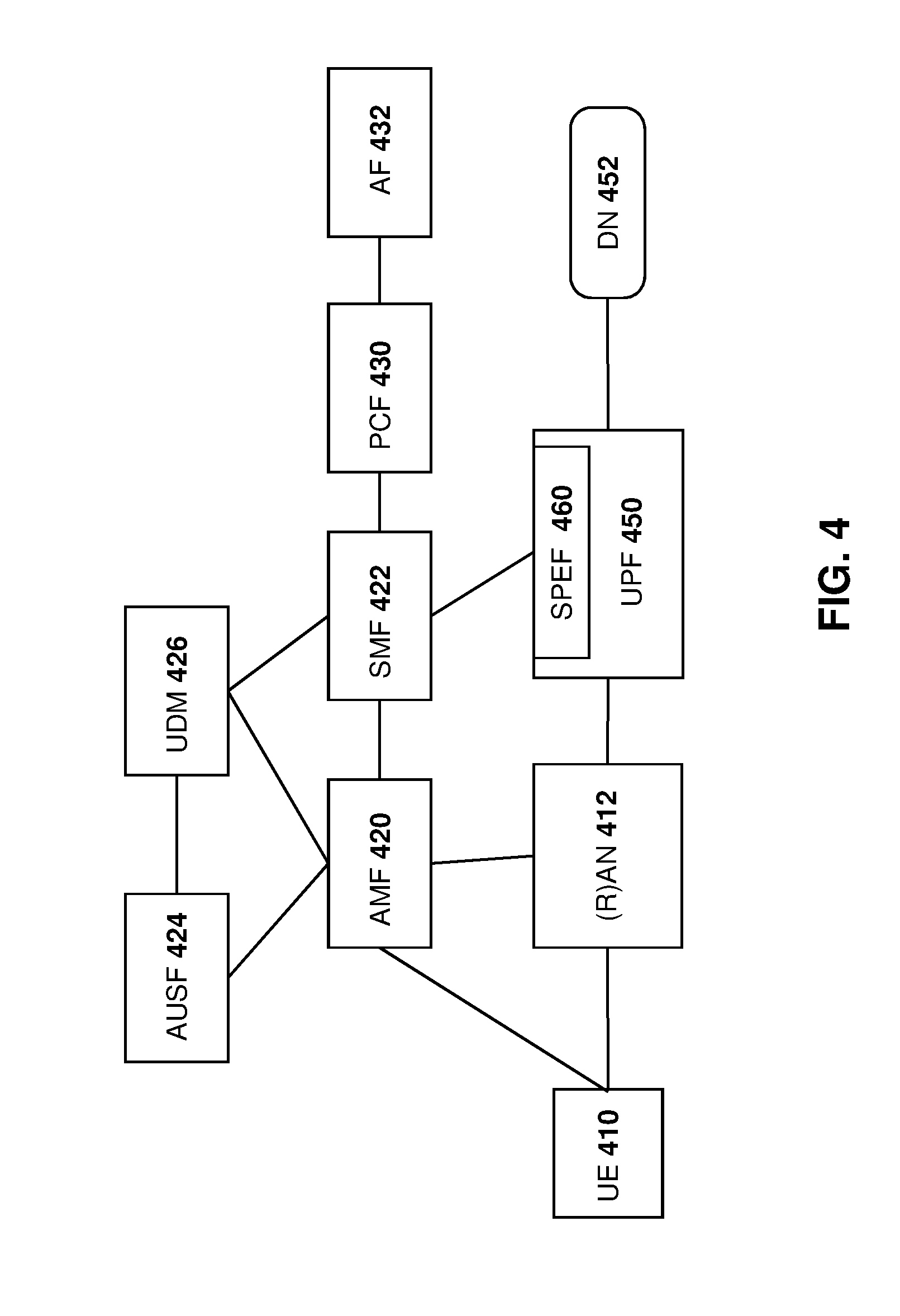
[0093] Reference is now made to FIG. 4, which shows an example of a 5G network. In particular, in the embodiment of FIG. 4, a UE 410 communicates with a (Radio) Access Network ((R)AN) 420. (R)AN 420 may further be referred to as a next generation Node B (gNB).
[0094] UE 410 may further communicate with an access and mobility management function (AMF) 420.
[0095] AMF 420 communicates with the authentication server function (AUSF) 422 and further with a Unified Data Management (UDM) module 424.
[0096] Further, AMF 420 also communicates with the session management function (SMF) 426.
[0097] A policy control function (PCF) 430 is responsible for policy control and communicates with SMF 426 and with the application function (AF) 432.
[0098] (R)AN 412 further communicates with AMF 420 and with a user plane function (UPF) 450. UPF 450 is similar to the P-GW 160 from the embodiments of FIGS. 1 and 3.
[0099] UPF 450 communicates with the data network 452, which may be network operator services, the Internet, third-party services, among other options.
[0100] In accordance with the embodiment of FIG. 4, SPEF 460 is added to the UPF 450. In this way, the SPEF 460 may identify any anomalous behavior by monitoring user plane traffic.
[0101] As indicated above, the embodiments of the present disclosure provide for three aspects. In a first aspect, the SPEF is configured. In a second aspect, the SPEF monitors user plane traffic to observe the set of characteristics and identify any anomalous behavior. In a third aspect, the detected anomalous behavior is acted on by invoking appropriate actions at a network element. Each are described below.
[0102] Configuration
[0103] In accordance with one embodiment of the present disclosure, an SPEF may be configured with a set of characteristics for communications between a user equipment and a network. Such characteristics are primarily related to the data communication in the user plane. The characteristics are known beforehand and/or can be set beforehand and therefore a session may be monitored by network infrastructure against observed behavior of transmissions.
[0104] Where deviation from the predefined characteristics is identified, this would indicate a possible security issue.
[0105] One set of characteristics is provided below in Table 3.
TABLE-US-00003 TABLE 3 Security Policy Enforcement Function parameters Example Range Name values Description SPE_LOC GPS coordinates UE LOCation: GPS co- within which the ordinates including UE shall be location/movement/speed located behaviour or other List of valid Cell information regarding the IDs or tracking physical location of the UE area IDs of the UE (cell-id). These may be known apriori for many UEs such as stationary UEs (e.g. smart meters). SPE_VOLUME Maximum amount Estimated data payload of data in a given volume. This may be period of time specified in the Max bytes subscription parameters per second (e.g. available in the HSS) Max data volume in a day/month etc SPE_TOD Expected time of Expected Time of Day/Day arrival (some of Week/Day of Month examples below) etc., for connection set up from 01:00 till 02:00 am every day weekdays only weekends only SPE_CONNS maximum number Expected number of of TCP/IP simultaneous data connections or connections (TCP/IP) from maximum number the UE of PDU data sessions per UE SPE_DUR maximum Expected duration of expected duration connection of a session (e.g. below) max duration 20 mins SPE_FREQ maximum number Estimated Frequency of of data packets data transmission (once sent in a given per hour/minute/second, duration of time or continuous) (examples below) Number of IP packets in an hour Number of IP packets per day/week SPE_DATATYPE Allowed data types Type of data; text, Image data numeric, video stream, Video data audio stream, graphics VoiP type (.jpg, .gif, .pdf), encrypted ftp payload (where the etc encryption is done at a Note that this may be layer above the radio layer identified based on the i.e. application layer) DSCP field in the IP header Alternatively, this may be also identified based on the payload type of the IP packet (e.g. TCP type payload or UDP etc). Further application level identification is also feasible if the node is capable of performing deep packet inspection. SPE_IPADDR allowed source Normal destination and/or destination address (IP address, URI, IP address/port or domain name or sub- numbers domain) SPE_BYTES maximum number Exchange of byte counts of bytes transmitted and received between the UE and Network over a specific connection. See Prior Art section below. SPE_CAPABILITY This similar to the Permitted subscription SPE_DATATYPE usage. For example, data mentioned above. only (no SMS, multi- media, voice (VolP) traffic allowed).
[0106] In Table 3 above, SPE refers to Security Policy Enforcement. The names of the security policy enforcement specified in Table 3 are however merely examples. Other enforcement characteristics could be defined at the SPEF.
[0107] In the Table 3 above, a location characteristic could be set which may include location, movement or speed behavior, or other information regarding the physical location of the UE. The Cell ID or Global Navigation Satellite System (GNSS) coordinates can be used to verify the location of the UE and crosscheck its position with a network value contained in the user profile for the UE to ensure the UE is in the location it should be, or in the region of its expected operation. A device found to be operating outside of its expected location could be flagged as a possible stolen device.
[0108] Further, volume information may be set estimating the payload data volume that would be sent from a UE or to a UE.
[0109] Time of day information may be set including when expected transmissions to or from the UE may occur.
[0110] A number of expected simultaneous connections can also be set. The expected duration of such connections may be a further characteristic that could be monitored.
[0111] Further, in some embodiments the estimated frequency of data transmission may be known. Thus, for example, if a weather beacon was expected to transmit every 30 minutes, such frequency could be set with this characteristic.
[0112] A datatype for the type of data that would be sent from the UE could also be known or set as a characteristic of the data that is expected from that UE.
[0113] Beacons may have a particular destination that they report to. For example, utilizing the weather beacon example, the weather beacon may send data to a particular server and to no other location. In this case, a characteristic could be the normal destination address for the communications.
[0114] A further characteristic that may be set may be the number of bytes that are expected to be transmitted in communications. For example, again using the weather beacon system, the UE may send a data packet that has a relatively known size and therefore upper limits on the size of the transmission could be set as a characteristic.
[0115] Further, capabilities for the UE could be set, indicating for example that the UE will send data and not SMS, multimedia packets, voice packets among others.
[0116] Many of the above parameters are related to traffic flow. Further, if packet payload inspection is used, many of the above parameters may be used with payload contents.
[0117] As described below, the above characteristics and ranges can be used by the network to compare the observed traffic against the parameters provided. If the observed traffic falls within the perimeter ranges provided, the network can have confidence of the traffic is valid.
[0118] A change in traffic flow can be viewed as a possible threat to the network. For example, changes to traffic with regard to frequency or volume may be associated with a denial of service attack, traffic changes to connection duration, data type, location, time of day, capability, source or destination IP address, byte counts, among others could indicate tampering. As described below, the network can then take appropriate action.
[0119] Further, in some embodiments, a device found operating outside of its expected parameters could simply be a malfunctioning device. Operators can then take measures to protect the network from a badly behaving or corrupted device and device owners may be notified of the problem.
[0120] The characteristics and ranges of Table 3 above may be preconfigured in the node that holds the subscription information. For example, in 3GPP network architecture, the functionality may reside in the PCF in 5G networks or the HSS in 4G networks.
[0121] Alternatively, the information with regard to the characteristics may be obtained directly from a UE for each session. In one embodiment, information from the UE regarding the characteristics may be provided only in integrity protected messages to ensure the validity of the parameters.
[0122] For example, during an ATTACH procedure, a UE is authenticated and can possibly securely send expected characteristics of the session in an integrity protected message. Since only an authenticated UE can send an integrity protected message, the parameter values included in the message can be trusted by the network. Based on the information, the set of characteristics and a range of values corresponding to the characteristics may be determined. These values may then, for example, be configured in the SPEF of the P-GW for 4G networks and in the UPF for 5G networks.
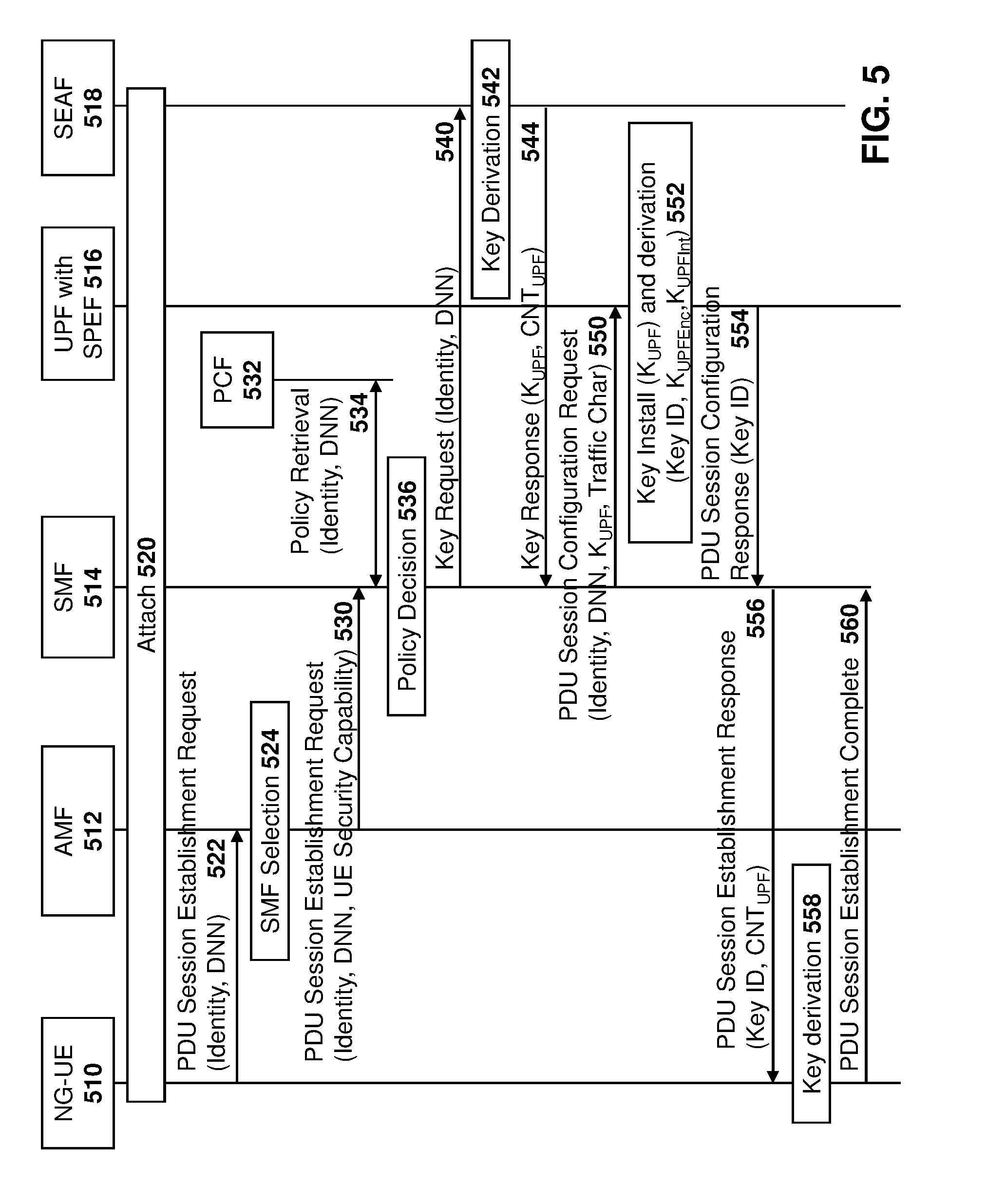
[0123] For example, reference is now made to FIG. 5, which shows the configuration of characteristics at the UPF in a 5G network.
[0124] In particular, in the embodiment of FIG. 5, a next-generation UE (NG-UE) 510 communicates with a 5G network, including AMF 512, SMF 514, UPF with SPEF 516 and Security Enforcement Access Framework (SEAF) 518.
[0125] As seen in block 520, the UE is attached with the network. This step involves mutual authentication of the network and the UE.
[0126] Optionally, in block 520, the UE may provide the expected characteristics of the session in a secure and integrity protected message. An example of such integrity protected message is a PDU session establishment request message 522 from the UE.
[0127] Message 522 may include an identity as well as a data network name (DNN). In one embodiment, the UE security capability, including user plane security capabilities, is stored in the AMF during the ATTACH. Alternatively, the NG-UE 510 may provide its user plane security capabilities in message 522.
[0128] Subsequently, at block 524, the AMF determines an SMF based on the DNN provided by NG-UE 510.
[0129] The AMF 512, once it has chosen an appropriate SMF, triggers the session establishment procedure by sending a PDU session establishment request to the SMF, shown by message 530. Message 530 includes the UE identity, DNN and security capability.
[0130] SMF 514 may then retrieve a security policy from PCF 532, as shown by arrow 534. In one embodiment, the security policy may include a set of characteristics and the range of values for each characteristic, as shown in the first two columns of Table 3 above.
[0131] Alternatively, the SMF 514 may determine the characteristics and ranges based on a policy retrieved from the PCF. In other embodiments, some or all of the values may also be attained directly from the UE during the ATTACH or PDU session establishment request 522. In this case, the values are passed to the SMF 514 from AMF 512.
[0132] At block 536, the SMF may check whether the NG-UE 510 is authorized to establish the requested PDU session and it determines the user plane security termination.
[0133] If the NG-UE 510 is authorized to establish the PDU session and UPF security termination is required for the PDU session, the SMF 512 may request a key for the UPF. The SMF 514 provides the SEAF 518 with the UE identity, DNN and SMF identity in message 540.
[0134] The SEAF derives a UPF Key (K.sub.UPF) from the K.sub.SEAF by incorporating the parameters received from the SMF 514 and a locally managed counter (for example CNT.sub.UPF) for UPF Key derivation. The key derivation is shown at block 542.
[0135] The SEAF 518 then sends a key response message 544 to the SMF 514. The key response includes the K.sub.UPF and CNT.sub.UPF used for the key derivation. Thus, the counter at block 542 is sent back.
[0136] On receiving message 544, SMF 514 sends a PDU session configuration request to the UPF containing the security configuration information for the PDU session. This may include, for example, the ciphering and/or integrity protection algorithm, including the K.sub.UPF and traffic characteristics for the PDU session. This is sent in message 550 in the embodiment of FIG. 5.
[0137] The UPF with the SPEF 516 installs the K.sub.UPF for the session as part of the PDU session configuration and derives subsequent keys such as K.sub.UPFEnc and K.sub.UPFInt. Such keys are derived based on security configuration information. The keys are associated with a key ID, which may also be incorporated in the key derivation. However, if integrity and confidentiality protection are not applied to the PDU session and the K.sub.UPF is null, there may be no derivation of the subsequent keys. Further, the UPF configures the security policy enforcement function with the traffic characteristic parameters received from the PCF from this PDU session. The key install is shown at block 552 in the embodiment of FIG. 5.
[0138] The UPF then sends a PDU session configuration response 554 to the SMF 514 containing a PDU session ID, key ID and other parameters if they exist, used for the key derivation.
[0139] The SMF 514 then sends a PDU session establishment response to the NG-UE 510 via the AMF 512, shown by message 556. This response message includes all key materials such as CNT.sub.UPF, key ID, among others, that are needed for the NG-UE 510 to derive the same keys as the UPF.
[0140] NG-UE 510 derives K.sub.UPF and subsequent keys based on the session establishment response at block 558.
[0141] The NG-UE 510 then sends a PDU session establishment complete message 560 to the SMF 514 via AMF 512.
[0142] After the completion of sending the message 560, NG-UE 510 and the UPF protect the user plane the packets based on the PDU session security configuration terminating at the UPF, which includes the SPEF.
[0143] Changes to 3GPP TR 33.899 which may accommodate the above are shown, for example, in Appendix C below. The additions to the TR are shown in bold.
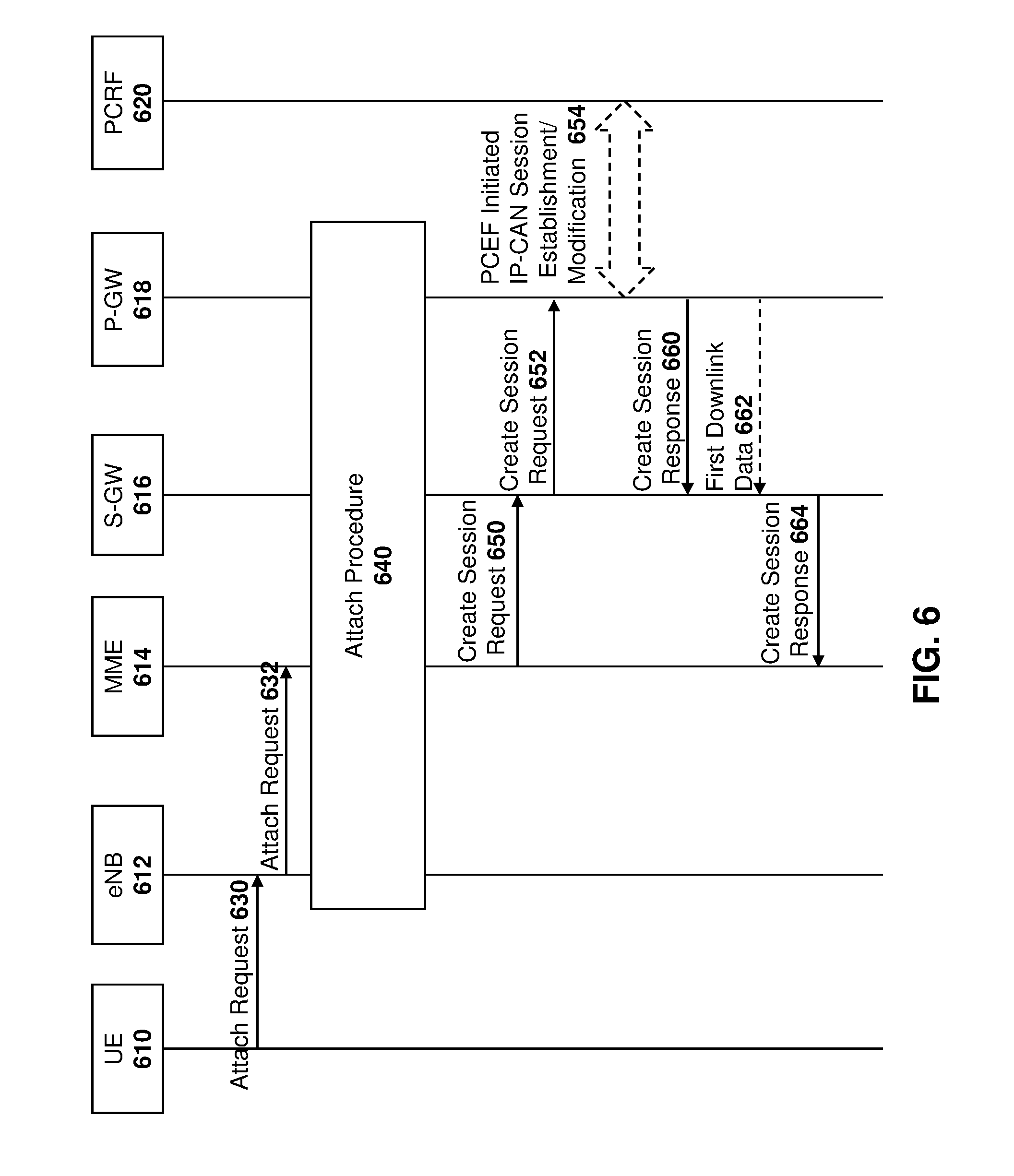
[0144] Similarly, the characteristics could be provided to the P-GW with a SPEF in a 4G network. For example, reference is now made to FIG. 6.
[0145] In the embodiment of FIG. 6, a UE 610 communicates with eNB 612. Further, network elements include MME 614, S-GW 616, P-GW 618 and Policy and Charging Rules Function (PCRF) 620.
[0146] At the outset, UE 610 makes an ATTACH request to eNB 612, as shown by message 630.
[0147] The eNB 612 forwards the ATTACH request to MME 614, as shown by message 632.
[0148] Thereafter, an ATTACH procedure, as for example defined in 3GPP TS 23.401, and namely steps 1-11 in Section 5.3.2.1 is performed, as shown by block 640 in the embodiment of FIG. 6.
[0149] If the subscription context does not indicate that the APN is for a PDN connection, MME 614 selects a serving gateway 616. It then sends a Create Session Request 650. Such Create Session Request may include various session request information, including security policy enforcement parameters.
[0150] Once serving gateway 616 receives request 650, it may then send a Create Session Request with standard information, as well as security policy enforcement parameters, to P-GW 618, shown as request 652.
[0151] The P-GW 618 may then perform an IP-CAN session establishment procedure with PCRF 620, as for example defined in 3GPP TS 23.203, and thereby obtains default Policy and Charging Control (PCC) rules for the UE. This is shown with arrow 654 in the embodiment of FIG. 6.
[0152] The P-GW 618 creates a new entry in its EPS bearer context table and generates a Charging ID for the default bearer. The new entry allows the P-GW 618 to route user plane PDUs between the S-GW 616 and the packet data network. If the SPEF parameters are present, the SPEF function will be invoked in the P-GW 618 and will commence monitoring the user plane PDUs for the UE 610.
[0153] The P-GW 618 will return to S-GW 616 a Create Session Response, shown as response 660.
[0154] If the ATTACH is not based on a handover then first downlink data, shown by arrow 662 may be received. At this point, S-GW 616 may send a Create Session Response to MME 614, as shown by message 664.
[0155] Monitoring of User Plane Traffic
[0156] Upon being configured with a set of characteristics and their valid ranges, as for example described with regard to FIGS. 5 and 6 above, the SPEF may start monitoring the mobile originated and mobile terminated traffic. If one or more characteristics of the user plane data are beyond the configured range, the SPEF may detect an anomaly, which may indicate a possible security vulnerability and may trigger an appropriate action based on the cause of the identified anomaly.
[0157] The monitoring may be for particular characteristics. In one embodiment, monitoring can occur by having each of the characteristics configured at the SPEF monitored separately. In other embodiments, the monitoring can occur for a plurality of characteristics.
[0158] Examples of monitoring are shown below with regard to the embodiments of FIGS. 7, 8 and 9. However, the embodiments in these figure are merely provided for illustration, and other examples of monitoring for particular characteristics would be apparent to those skilled in the art having regard to the present disclosure.
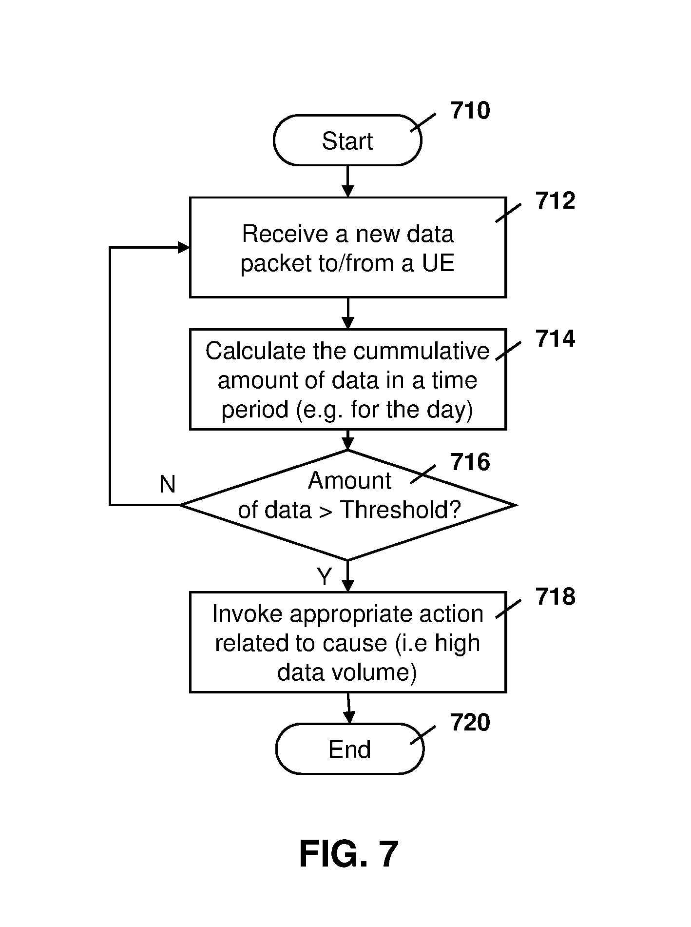
[0159] Referring to FIG. 7, the embodiment shows a process at the SPEF for monitoring for data volume. In particular, the process of FIG. 7 starts at block 710 and proceeds to block 712 in which new data packets that are destined for a UE or are from a UE are received.
[0160] The process then proceeds to block 714 in which a calculation is done on the cumulative amount of data that has been received by a UE or is sent to the UE for a particular time period. For example, if the configuration for a UE has been set with a characteristic that expects a certain amount of data for the UE for each given day, the calculation at block 714 may calculate the cumulative data for that time period. In other embodiments, the time period may be one hour, a number of minutes, one week, one month, among other time periods.
[0161] The process then proceeds to block 716 in which a check is made to determine whether the amount of data received in the time period exceeds a threshold for the expected amount of data from the UE or to the UE. For example, if the UE is expected to send less than 1 MB of data per day and the cumulative amount of data sent from the UE has exceeded the 1 MB, then the check at block 716 is affirmative and the process proceeds to block 718.
[0162] At block 718, if the amount of data has exceeded the threshold, then an appropriate action is invoked related to the cause of high volume data. Example actions are described below.
[0163] Conversely, if the amount of data is less than the threshold, then the process proceeds from block 716 back to block 712 in which the process waits for the next data to be received for or from the UE.
[0164] From block 718 the process proceeds to block 720 and ends.
[0165] Thus, in accordance with the embodiment of FIG. 7, a network element may monitor data traffic to or from a UE to ensure that the amount of data does not exceed a threshold for a time period.
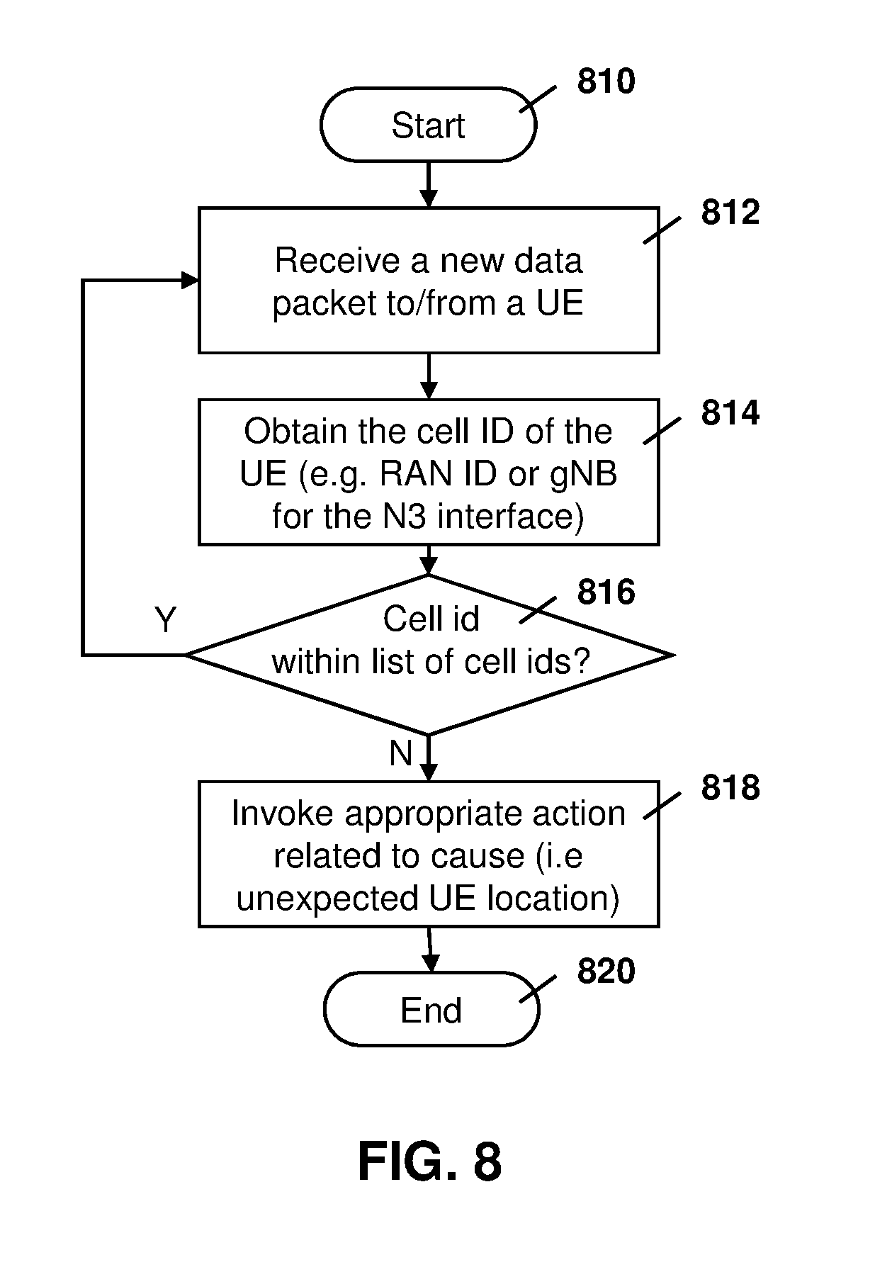
[0166] Reference is now made to FIG. 8, which shows a process for monitoring location of a UE at the SPEF. In particular, the process starts at block 810 and proceeds to block 812 in which a new data packet has been received that is destined for a UE or a new data packet has been received from a UE.
[0167] The process then proceeds to block 814 in which the location of the UE is determined. For example, in one embodiment the location may be determined based on the cell identifier of the UE. This may, for example, be the Radio Access Network Identifier (RAN ID) or the eNB identifier for the N3 interface in one embodiment. However, location may be determined in a variety of ways and the obtaining of the location of block 814 could use different methods.
[0168] From block 814 the process proceeds to block 816 in which the check is made to determine whether the cellular identifier is within a list of cellular identifiers configured as a characteristic for that particular UE. For example, if a UE is meant to be a stationary UE such as a parking meter, then the movement of the UE to a different cell ID may indicate that the UE has been stolen or is being spoofed.
[0169] From block 816, if the cell ID is within the list of parameters for the location characteristic, the process proceeds back to block 814 to wait for new packet data to or from the UE.
[0170] Conversely, if the cell ID is not within the list of cell ID parameters, as determined at block 816, then the process proceeds to block 818 in which appropriate actions are invoked related to the cause of an unexpected UE location. Examples of actions are described below.
[0171] From block 818 the process proceeds to block 820 and ends
[0172] Thus, based on FIG. 8, the SPEF may monitor the location of a UE to ensure that the location for the UE is expected.
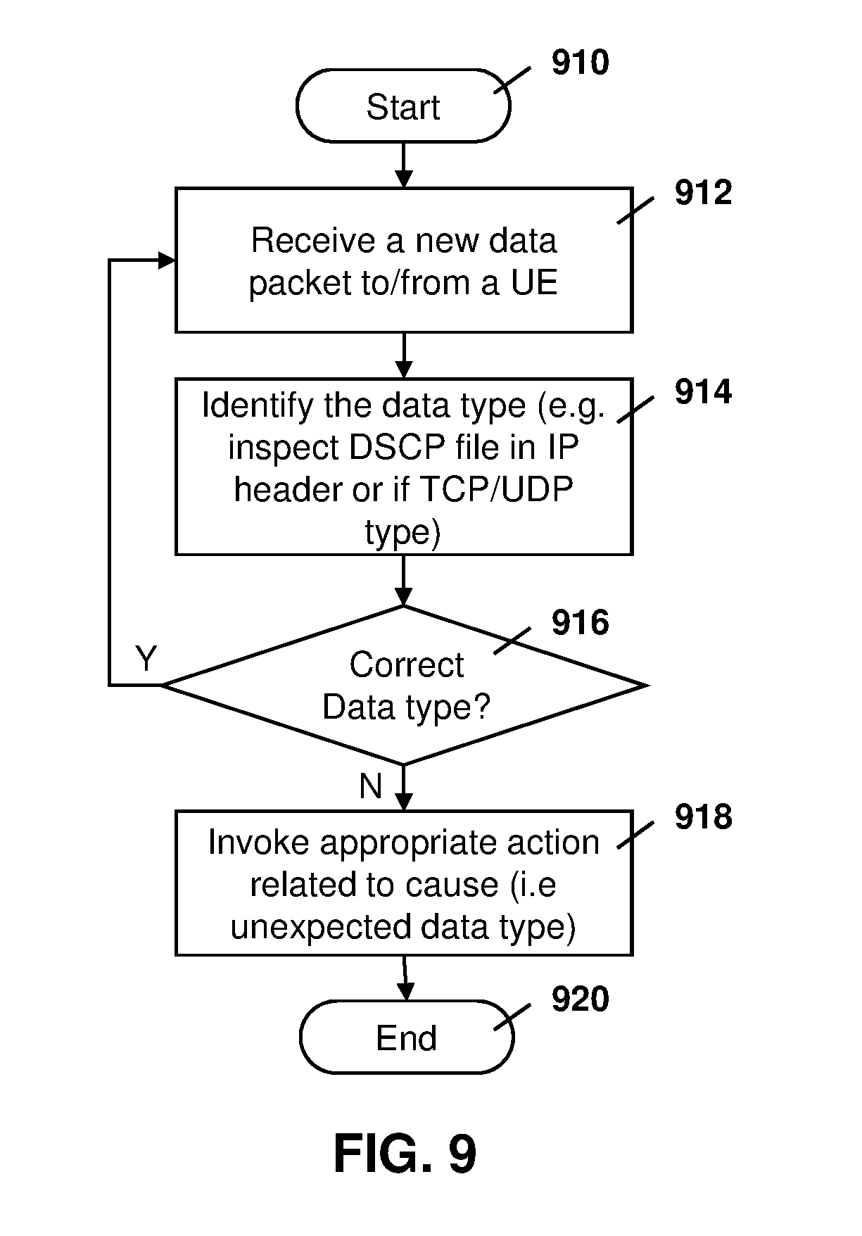
[0173] Reference is now made to FIG. 9, which shows a process at an SPEF for data type monitoring functionality. In particular, the process of FIG. 9 starts at block 910 and proceeds to block 912 in which a new data packet destined for a UE or a new packet from a UE is received.
[0174] The process then proceeds to block 914 in which a data type is identified for the data packet. For example, the data type may be identified by inspecting the Differentiated Services Code Point (DSCP) field in the IP header or by identifying whether the packet is a Transmission Control Protocol/User Datagram Protocol (TCP/UDP) type packet.
[0175] Other methods for defining the data type are also possible and the present disclosure is not limited to any particular method for identifying the datatype at block 914.
[0176] From block 914 the process proceeds to block 916 and checks whether the data type is the correct data type. The check could use parameters associated with data type characteristics that have been configured for the UE. Such parameters allow the SPEF to determine whether the UE is allowed to send the packet with the datatype identified at block 914.
[0177] If the datatype is the correct datatype, the process proceeds to block 912 in which the process waits for the next data packet to or from the UE.
[0178] Conversely, if the datatype at block 916 is identified to be an incorrect datatype, then the process proceeds to block 918 in which an appropriate action related to a cause is invoked, where the cause is set to unexpected datatype. For example, in the parking meter example, the parking meter may be expected to send TCP packets. However, if a Short Message Service (SMS) message is received then this could be identified as an incorrect datatype and an action invoked at block 918 made be reflective of this. Actions are described below.
[0179] The process proceeds to block 920 and ends.
[0180] Thus the embodiment of FIG. 9 shows an example process for monitoring datatypes for traffic originating from a UE or traffic destined to a UE.
[0181] The examples of FIGS. 7, 8 and 9 are provided for illustration. Similar processes could be used for the different characteristics configured at the SPEF for the UE to determine whether or not the user plane traffic is within parameters specified for such characteristics
[0182] Triggering Appropriate Actions
[0183] Upon detecting one or more anomalies in user plane traffic, the SPEF may trigger an appropriate action specific to the detected set of anomalies. Some actions may include simple user plane functionality such as dropping packets while other actions may include control plane functionality such as triggering specific 3GPP control plane procedures.
[0184] Various example actions are provided below. However, the list of actions is merely provided for illustration, and other actions could also be performed. The actions described below are therefore not limiting.
[0185] Trigger Alarms Sent to a PLMN Network Management Function
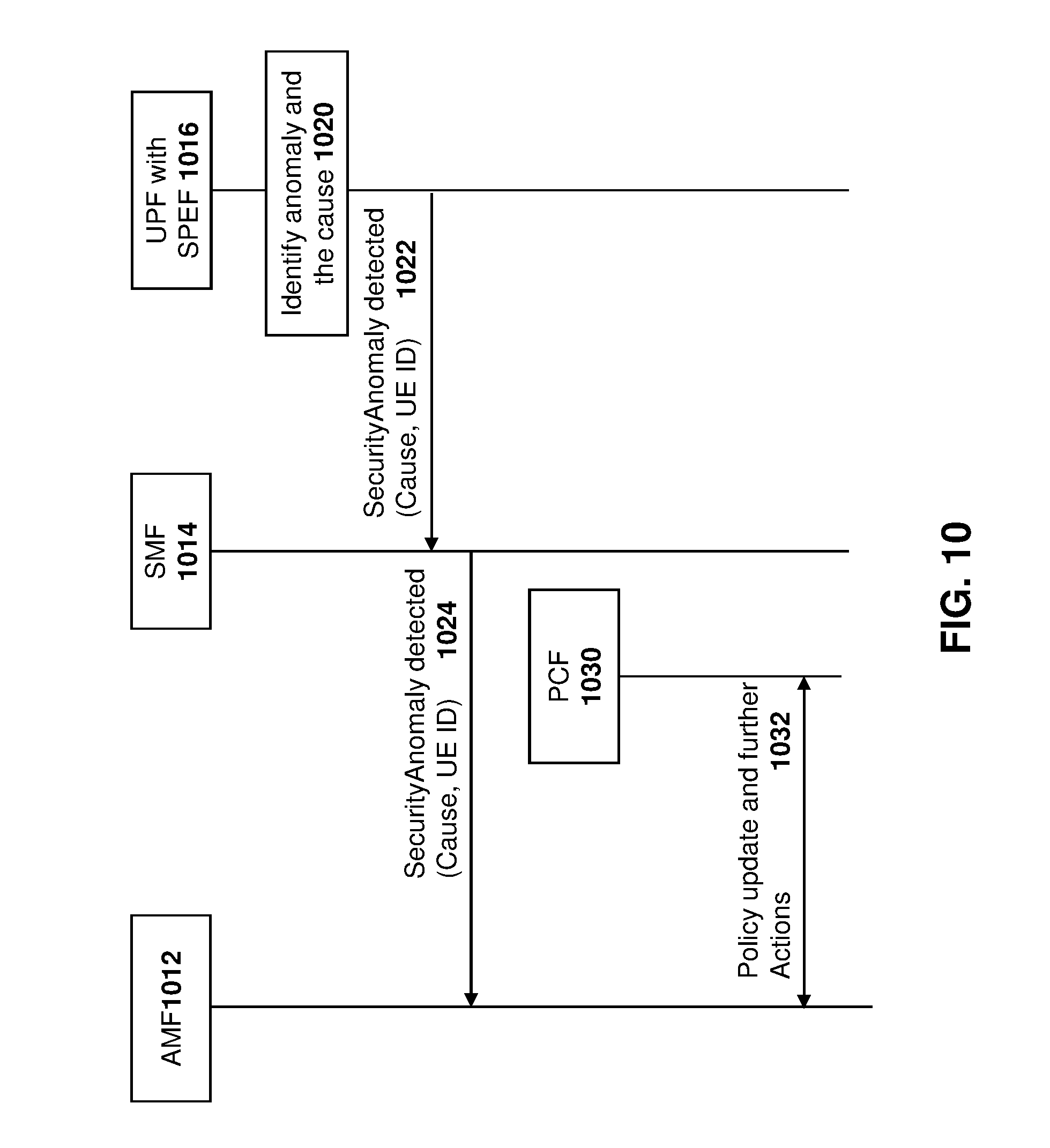
[0186] Reference is made to FIG. 10. In a first example of an action, control plane nodes such as the SMF 1014, AMF 1012 and PCF 1030 may be involved in executing the action. In particular, the action in the example of FIG. 10 involves policy updates with the PCF 1030.
[0187] In the example of FIG. 10, the UPF with the SPEF 1016 may identify an anomaly and the cause of the anomaly at block 1020. Based on the anomaly and cause, the UPF may then send a message 1022 to the SMF 1014 indicating that a security anomaly has been detected. The message 1022 may include a cause, as well as a user equipment identifier.
[0188] SMF 1014 may then forward the contents of message 1022 to AMF 1012, shown as message 1024, with the cause and the user equipment identifier.
[0189] Upon receiving the message 1024, AMF 1012 may update the policy record in the PCF 1030, shown with policy update 1032. The updating may trigger further actions such as notifying the user, requiring user plane security, among other actions, as provided below.
[0190] Trigger a Notification to the Device Owner
[0191] Reference is now made to FIG. 11, which shows an action that may be invoked by control plane nodes SMF 1114, AMF 1112 and the UPF with the SPEF 1116. In the example of FIG. 11, the UE 1110 receives a notification.
[0192] In the example of FIG. 11, the UPF with the SPEF 1116 identifies an anomaly in a cause, shown at block 1120. The UPF may then send a message 1122 to SMF 1114, indicating that a security anomaly has been detected. Message 1122 may include a cause and a user equipment identifier.
[0193] SMF 1114 may then forward the contents of message 1122 to the AMF 1112, shown as message 1124.
[0194] AMF 1112 may then forward, to the UE 1110, a message indicating that a vulnerability has been detected and cause of the vulnerability. This is shown as message 1126 in the embodiment of FIG. 11. Message 1126 may be a secure Network Access Stratum (NAS) message in one embodiment. Thus, message 1126 may be encrypted and/or integrity protected to ensure that only the authentic UE is informed about the detected vulnerability, since only the authentic UE will have the keys needed for integrity and decryption.
[0195] Drop the Packets to or from the Concerned UE
[0196] In another embodiment, only one user plane node such as the UPF may be involved with the action. Reference is now made to FIG. 12 which shows a UPF with the SPEF 1216 being involved with user plane traffic. Further, messages may be forwarded through SMF 1214, AMF 1212, and the gNB 1218. Further, the UE 1210 receives control plane messages.
[0197] In the embodiment of FIG. 12, the UPF with the SPEF 1216 identifies an anomaly and a cause at block 1220 and may then drop the packets to and from the UE at block 1222.
[0198] In one embodiment, this may be the end of the action.
[0199] In other embodiments, the UPF may optionally trigger to the gNB to drop the packets from the UE, which could save the traffic hitting the core network nodes between the RAN node and the UPF. In this case, a control plane node such as the AMF 1212 and the SMF 1214 may need to be involved with such functionality.
[0200] In particular, in the embodiment of FIG. 12, the UPF may send a message 1230 to drop packets from the UE, including a user equipment identifier and a cause. Message 1230 may be sent to SMF 1214.
[0201] SMF 1214 may then forward the contents of message 1230, shown as message 1232, to AMF 1212.
[0202] AMF 1212 may then forward the contents of message 1232, shown as message 1234, to gNB 1218.
[0203] On receiving message 1234, the gNB 1218 may discard user plane (UP) traffic from the UE and/or invoke the RRC release procedure for the UE, as shown at block 1240. In the latter case, if an RRC release is invoked then the RRC release is sent to the UE, as shown by arrow 1242 and the UE may then enter an IDLE mode, as shown by block 1250
[0204] Trigger an Integrity Check or Counter Check Procedure
[0205] In a further action, a procedure may be initiated by a RAN node such as the gNB in 5G networks. However, a trigger to initiate the procedure may come from any core network node.
[0206] Reference is now made to FIG. 13. In the embodiment of FIG. 13, the SPEF may cause the RAN node to trigger a counter check procedure upon detecting a specific anomaly.
[0207] In the embodiment of FIG. 13, UE 1310 may communicate with a RAN node such as gNB 1318. Further, core network node such as AMF 1312 and SMF 1314 may be involved in communication with UPF and SPEF 1316.
[0208] The UPF with SPEF 1316 may identify an anomaly and a cause, as shown by block 1320, and may in one embodiment drop the user plane packets to and from the UE as shown by block 1322.
[0209] Further, in the embodiment of FIG. 13, the UPF with the SPEF 1316 may signal a security anomaly has been detected, along with a cause and a user equipment identifier, and send this as a message 1330 to the SMF 1314.
[0210] The SMF 1314 may forward the contents of message 1330, shown as message 1332, to the AMF 1312.
[0211] AMF 1312 may then forward the contents of message 1332 to the gNB 1318, as shown by message 1334.
[0212] On receiving message 1334, the gNB 1318 may initiate a counter check procedure. If the counter check fails, the RRC connection may be released and this may be indicated to the AMF 1312 and one embodiment. Further, if the counter check succeeds, the gNB 1318 may indicate the success to the AMF 1312.
[0213] The initial counter check procedure is shown by block 1340 in the embodiment of FIG. 13.
[0214] Based on the check at block 1340, if the counter check fails, an RRC release may be initiated as shown by arrow 1342 in FIG. 13.
[0215] On receiving the RRC release, the UE may enter an idle mode, shown by Block 1350.
[0216] Trigger an Authentication Procedure
[0217] In still a further action, upon detecting an anomaly, the SPEF may trigger an authentication procedure for the UE. Reference is now made to FIG. 14.
[0218] In the embodiment of FIG. 14, an NAS authentication procedure is triggered by the AMF. Specifically, UE 1410 communicates with AMF 1412. Further, the core network includes SMF 1414 and user plane data is monitored by UPF with SPEF 1416.
[0219] The UPF with the SPEF 1416 identifies an anomaly and cause, as shown by block 1420, and based on the detected anomaly and cause provides a message 1422 to the SMF 1414 indicating that a security anomaly has been detected. Message 1422 may include a cause and a user equipment identifier.
[0220] SMF 1414 then forwards the contents of message 1422 to the AMF 1412, shown as message 1424.
[0221] Based on message 1424, AMF 1412 initiates an authentication procedure. In particular, an authentication request message 1430 may be sent to UE 1410.
[0222] In response, an authentication response message 1432 may be provided from the UE 1410 back to AMF 1412.
[0223] AMF 1412 verifies the response in message 1432 to determine whether authentication has passed or failed. Further, the absence of a response may also indicate authentication has failed. The authentication check is shown at block 1440 in the embodiment of FIG. 14.
[0224] If the authentication fails, a DETACH procedure may be initiated for the UE. One example DETACH procedure is described below with regards to FIG. 17.
[0225] Conversely, if the authentication succeeds, the session is continued and an indication may be sent to the SPEF via the SMF 1414.
[0226] Thus, if the authentication is successful then the UE is re-authenticated as shown by message 1442 between AMF 1412 and SMF 1414. SMF 1414 then forwards the contents of message 1442 to the UPF 1416, shown as message 1444.
[0227] Trigger a Connection Re-Establishment Procedure
[0228] A further action that may occur would be to trigger a DETACH procedure for the UE upon detecting an anomaly. In this case, a genuine UE may perform a new ATTACH procedure, including authentication, subsequent to the DETACH procedure.
[0229] Reference is now made to FIG. 15. In particular, in the embodiment of FIG. 15, UE 1510 communicates with the network using gNB 1518. The core network includes AMF 1512 and SMF 1514. Further, UPF with SPEF 1516 provides for user plane traffic.
[0230] The UPF with the SPEF 1516 identifies an anomaly and a cause at block 1520. The UPF with the SPEF 1516 then signals a security anomaly has been detected, including the cause and a user equipment identifier, in message 1530 to the SMF 1514.
[0231] SMF 1514 may then forward the contents of message 1530 to AMF 1512, shown as message 1532.
[0232] AMF 1512 may then send a DETACH ACCEPT message 1534 to the gNB 1518, which may cause an RRC release 1540 with the UE 1510.
[0233] As indicated above, a genuine UE 1510 could then perform an ATTACH procedure with the authentication security.
[0234] One example DETACH procedure is shown with regards to FIG. 17 below.
[0235] Switch on Encryption and/or Integrity Protection
[0236] In a further action, the SPEF may trigger the radio node to switch on the encryption and/or integrity protection of data. Such trigger may be a temporary trigger in some embodiments. Reference is now made to FIG. 16.
[0237] UE 1610 communicates using gNB 1618. Further, the core network includes AMF 1612 and SMF 1614. A UPF with SPEF 1616 provides for user plane traffic.
[0238] In the embodiment of FIG. 16, the UPF with the SPEF 1616 identifies an anomaly and a cause at block 1620 and provides a message 1630 to SMF 1614 indicating that a security anomaly has been detected. Message 1630 may include a cause and a user equipment identifier.
[0239] SMF 1614 may then forward the contents of message 1630 to AMF 1612, shown as message 1632.
[0240] AMF 1612 may then trigger a session modification to turn on encryption or integrity protection, as shown by message 1634, with gNB 1618.
[0241] Based on the receipt of message 1634, gNB 1618 may then cause an RRC-reconfiguration. The RRC reconfiguration 1640 may include the data radio bearer being reconfigured to use encryption and/or integrity protection.
[0242] Once UE 1610 receives the RRC reconfiguration 1640, only a genuine UE can succeed in switching encryption and/or integrity protection on, since this requires the UE to be in possession of the appropriate security keys.
[0243] DETACH
[0244] In the actions shown with regard to FIGS. 14 and 15 above, the UE is caused to DETACH. This may be accomplished in various ways.
[0245] One example of a detach for a 4G network is provided with regard to FIG. 17. In particular, the embodiment of FIG. 17 shows a 4G network causing a new DETACH notification 1720 to be sent between a P-GW 1710 and an MME 1712. For example, the DETACH notification 1720 may to be sent from the SPEF associated with P-GW 1710.
[0246] DETACH notification 1720 provides an indication that the observed traffic behavior is outside an expected range.
[0247] On receiving the DETACH notification 1720, the MME may perform a DETACH procedure as, for example, described in 3GPP TR 23.401 and in particular in section 5.8.3.1 of that TR. Such DETACH procedure is shown by block 1730 in the embodiment of FIG. 17.
[0248] Based on the DETACH procedure, the P-GW 1710 will receive a delete session request and send a delete session response for the requested user data PDU's session (not shown).
[0249] Upon conclusion of the DETACH procedure at block 1730, the MME 1712 sends a final DETACH acknowledgement, shown by message 1740, to the P-GW 1710. In particular, the DETACH acknowledgement 1740 may be sent to the SPEF associated with the P-GW 1710.
[0250] One example of changes to 3GPP TR 23.401 that could be made for the above detach procedure are shown in Appendix E below.
[0251] For a 5G network, a similar detach procedure could be utilized.
[0252] The above therefore provides for the ability to reduce processing power and increase battery life of potentially millions of UEs deployed in IoT applications by removing the need to run integrity and confidentiality at the radio interface. Further, a reduction is created in over the air data transfer that is needed to support integrity, which results in more bandwidth available for the network to support other customers.
[0253] The embodiments further offer protection to the network for potential misuse of the radio interface against spoofing and DoS attacks.
[0254] The embodiments described above can also provide protection for a device owner or user if the device was stolen and/or the subscription used fraudulently.
[0255] Further, a malfunctioning device may be detected in accordance with the embodiments described above, thus protecting the network and device owner or user.
[0256] The modules, mobile entities, and user equipments and devices described above may be any computing device or network node. Such computing device or network node may include any type of electronic device, including but not limited to, mobile devices such as smartphones or cellular telephones. Examples can further include fixed or mobile user equipments, such as internet of things (IoT) devices, endpoints, home automation devices, medical equipment in hospital or home environments, inventory tracking devices, environmental monitoring devices, energy management devices, infrastructure management devices, vehicles or devices for vehicles, fixed electronic devices, among others. Vehicles includes motor vehicles (e.g., automobiles, cars, trucks, buses, motorcycles, etc.), aircraft (e.g., airplanes, unmanned aerial vehicles, unmanned aircraft systems, drones, helicopters, etc.), spacecraft (e.g., spaceplanes, space shuttles, space capsules, space stations, satellites, etc.), watercraft (e.g., ships, boats, hovercraft, submarines, etc.), railed vehicles (e.g., trains and trams, etc.), and other types of vehicles including any combinations of any of the foregoing, whether currently existing or after arising.
[0257] One simplified diagram of a computing device is shown with regard to FIG. 18. The computing device of FIG. 18 could be any UE, Mobile Entity (ME), network node such as UPF, SPEF, or other node as described above.
[0258] In FIG. 18, device 1810 includes a processor 1820 and a communications subsystem 1830, where the processor 1820 and communications subsystem 1830 cooperate to perform the methods of the embodiments described above. Communications subsystem 1820 may, in some embodiments, comprise multiple subsystems, for example for different radio technologies.
[0259] Processor 1820 is configured to execute programmable logic, which may be stored, along with data, on device 1810, and shown in the example of FIG. 18 as memory 1840. Memory 1840 can be any tangible, non-transitory computer readable storage medium. The computer readable storage medium may be a tangible or in transitory/non-transitory medium such as optical (e.g., CD, DVD, etc.), magnetic (e.g., tape), flash drive, hard drive, or other memory known in the art.
[0260] Alternatively, or in addition to memory 1840, device 1810 may access data or programmable logic from an external storage medium, for example through communications subsystem 1830.
[0261] Communications subsystem 1830 allows device 1810 to communicate with other devices or network elements and may vary based on the type of communication being performed. Further, communications subsystem 1830 may comprise a plurality of communications technologies, including any wired or wireless communications technology.
[0262] Communications between the various elements of device 1810 may be through an internal bus 1860 in one embodiment. However, other forms of communication are possible.
[0263] Further, if the computing station is a user equipment, one example user equipment is described below with regard to FIG. 19.
[0264] User equipment 1900 may comprise a two-way wireless communication device having voice or data communication capabilities or both. User equipment 1900 generally has the capability to communicate with other computer systems. Depending on the exact functionality provided, the user equipment may be referred to as a data messaging device, a two-way pager, a wireless e-mail device, a smartphone, a cellular telephone with data messaging capabilities, a wireless Internet appliance, a wireless device, a mobile device, a mobile entity, an embedded cellular modem or a data communication device, as examples.
[0265] Where user equipment 1900 is enabled for two-way communication, it may incorporate a communication subsystem 1911, including a receiver 1912 and a transmitter 1914, as well as associated components such as one or more antenna elements 1916 and 1918, local oscillators (LOs) 1913, and a processing module such as a digital signal processor (DSP) 1920. As will be apparent to those skilled in the field of communications, the particular design of the communication subsystem 1911 will be dependent upon the communication network in which the user equipment is intended to operate.
[0266] Network access requirements will also vary depending upon the type of network 1919. In some networks, network access is associated with a subscriber or user of the user equipment 1900. A user equipment may be provided with an embedded or a removable user identity module (RUIM) or a subscriber identity module (SIM) card or a UMTS SIM (USIM) in order to operate on a network. The USIM/SIM/RUIM interface 1944 is normally similar to a card-slot into which a USIM/SIM/RUIM card can be inserted and ejected. The USIM/SIM/RUIM card can have memory and hold many key configurations 1951, and other information 1953 such as identification, and subscriber related information. In other cases, rather than a network 1919, user equipment 1900 may communicate with a non-access node, such as a vehicle, roadside infrastructure, another user equipment, or other peer-to-peer communication.
[0267] When required network registration or activation procedures have been completed, user equipment 1900 may send and receive communication signals over the network 1919. As illustrated in FIG. 19, network 1919 can include multiple base stations communicating with the user equipment.
[0268] Signals received by antenna 1916 through communication network 1919 are input to receiver 1912, which may perform such common receiver functions as signal amplification, frequency down conversion, filtering, channel selection and the like. Analog to digital (A/D) conversion of a received signal allows more complex communication functions such as demodulation and decoding to be performed in the DSP 1920. In a similar manner, signals to be transmitted are processed, including modulation and encoding for example, by DSP 1920 and input to transmitter 1914 for digital to analog (D/A) conversion, frequency up conversion, filtering, amplification and transmission over the communication network 1919 via antenna 1918. DSP 1920 not only processes communication signals, but also provides for receiver and transmitter control. For example, the gains applied to communication signals in receiver 1912 and transmitter 1914 may be adaptively controlled through automatic gain control algorithms implemented in DSP 1920.
[0269] User equipment 1900 generally includes a processor 1938 which controls the overall operation of the device. Communication functions, including data and voice communications, are performed through communication subsystem 1911. Processor 1938 also interacts with further device subsystems such as the display 1922, flash memory 1924, random access memory (RAM) 1926, auxiliary input/output (I/O) subsystems 1928, serial port 1930, one or more keyboards or keypads 1932, speaker 1934, microphone 1936, other communication subsystem 1940 such as a short-range communications subsystem or DSRC subsystem, and any other device subsystems generally designated as 1942. Serial port 1930 could include a USB port, On-Board Diagnostics (OBD) port or other port known to those in the art.
[0270] Some of the subsystems shown in FIG. 19 perform communication-related functions, whereas other subsystems may provide "resident" or on-device functions. Notably, some subsystems, such as keyboard 1932 and display 1922, for example, may be used for both communication-related functions, such as entering a text message for transmission over a communication network, and device-resident functions such as a calculator or task list.
[0271] Operating system software used by the processor 1938 may be stored in a persistent store such as flash memory 1924, which may instead be a read-only memory (ROM) or similar storage element (not shown). Those skilled in the art will appreciate that the operating system, specific device applications, or parts thereof, may be temporarily loaded into a volatile memory such as RAM 1926. Received communication signals may also be stored in RAM 1926.
[0272] As shown, flash memory 1924 can be segregated into different areas for both computer programs 1958 and program data storage 1950, 1952, 1954 and 1956. These different storage types indicate that each program can allocate a portion of flash memory 1924 for their own data storage requirements. Processor 1938, in addition to its operating system functions, may enable execution of software applications on the user equipment. A predetermined set of applications that control basic operations, including potentially data and voice communication applications for example, will normally be installed on user equipment 1900 during manufacturing. Other applications could be installed subsequently or dynamically.
[0273] Applications and software may be stored on any computer readable storage medium. The computer readable storage medium may be a tangible or in transitory/non-transitory medium such as optical (e.g., CD, DVD, etc.), magnetic (e.g., tape) or other memory known in the art.
[0274] One software application may be a personal information manager (PIM) application having the ability to organize and manage data items relating to the user of the user equipment such as, but not limited to, e-mail, messages, calendar events, voice mails, appointments, and task items. Further applications, including productivity applications, social media applications, games, among others, may also be loaded onto the user equipment 1900 through the network 1919, an auxiliary I/O subsystem 1928, serial port 1930, short-range communications subsystem 1940 or any other suitable subsystem 1942, and installed by a user in the RAM 1926 or a non-volatile store (not shown) for execution by the processor 1938. Such flexibility in application installation increases the functionality of the device and may provide enhanced on-device functions, communication-related functions, or both.
[0275] In a data communication mode, a received signal such as a text message or web page download will be processed by the communication subsystem 1911 and input to the processor 1938, which may further process the received signal for output to the display 1922, or alternatively to an auxiliary I/O device 1928.
[0276] A user of user equipment 1900 may also compose data items such as messages for example, using the keyboard 1932, which may be a complete alphanumeric keyboard or telephone-type keypad, either physical or virtual, among others, in conjunction with the display 1922 and possibly an auxiliary I/O device 1928. Such composed items may then be transmitted over a communication network through the communication subsystem 1911.
[0277] Where voice communications are provided, overall operation of user equipment 1900 is similar, except that received signals may typically be output to a speaker 1934 and signals for transmission may be generated by a microphone 1936. Alternative voice or audio I/O subsystems, such as a voice message recording subsystem, may also be implemented on user equipment 1900. Although voice or audio signal output is preferably accomplished primarily through the speaker 1934, display 1922 may also be used to provide an indication of the identity of a calling party, the duration of a voice call, or other voice call related information for example.
[0278] Serial port 1930 in FIG. 19 may be implemented in a user equipment for which synchronization with a user's desktop computer (not shown) may be desirable, but is an optional device component. Such a port 1930 may enable a user to set preferences through an external device or software application and may extend the capabilities of user equipment 1900 by providing for information or software downloads to user equipment 1900 other than through a wireless communication network. As will be appreciated by those skilled in the art, serial port 1930 can further be used to connect the user equipment to a computer to act as a modem or for charging a battery on the user equipment.
[0279] Other communications subsystems 1940, such as a short-range communications subsystem, is a further component which may provide for communication between user equipment 1900 and different systems or devices, which need not necessarily be similar devices. For example, the subsystem 1940 may include an infrared device and associated circuits and components or a Bluetooth.TM. or Bluetooth.TM. Low Energy communication module to provide for communication with similarly enabled systems and devices. Subsystem 1940 may further include non-cellular communications such as Wi-Fi or WiMAX, or near field communications, and in accordance with the embodiments above such radio may be capable of being split in some circumstances.
[0280] The embodiments described herein are examples of structures, systems or methods having elements corresponding to elements of the techniques of this application. This written description may enable those skilled in the art to make and use embodiments having alternative elements that likewise correspond to the elements of the techniques of this application. The intended scope of the techniques of this application thus includes other structures, systems or methods that do not differ from the techniques of this application as described herein, and further includes other structures, systems or methods with insubstantial differences from the techniques of this application as described herein.
[0281] While operations are depicted in the drawings in a particular order, this should not be understood as requiring that such operations be performed in the particular order shown or in sequential order, or that all illustrated operations be performed, to achieve desirable results. In certain circumstances, multitasking and parallel processing may be employed. Moreover, the separation of various system components in the implementation described above should not be understood as requiring such separation in all implementations, and it should be understood that the described program components and systems can generally be integrated together in a signal software product or packaged into multiple software products.
[0282] Also, techniques, systems, subsystems, and methods described and illustrated in the various implementations as discrete or separate may be combined or integrated with other systems, modules, techniques, or methods. Other items shown or discussed as coupled or directly coupled or communicating with each other may be indirectly coupled or communicating through some interface, device, or intermediate component, whether electrically, mechanically, or otherwise. Other examples of changes, substitutions, and alterations are ascertainable by one skilled in the art and may be made.
[0283] While the above detailed description has shown, described, and pointed out the fundamental novel features of the disclosure as applied to various implementations, it will be understood that various omissions, substitutions, and changes in the form and details of the system illustrated may be made by those skilled in the art. In addition, the order of method steps are not implied by the order they appear in the claims.
[0284] When messages are sent to/from an electronic device, such operations may not be immediate or from the server directly. They may be synchronously or asynchronously delivered, from a server or other computing system infrastructure supporting the devices/methods/systems described herein. The foregoing steps may include, in whole or in part, synchronous/asynchronous communications to/from the device/infrastructure. Moreover, communication from the electronic device may be to one or more endpoints on a network. These endpoints may be serviced by a server, a distributed computing system, a stream processor, etc. Content Delivery Networks (CDNs) may also provide may provide communication to an electronic device. For example, rather than a typical server response, the server may also provision or indicate a data for content delivery network (CDN) to await download by the electronic device at a later time, such as a subsequent activity of electronic device. Thus, data may be sent directly from the server, or other infrastructure, such as a distributed infrastructure, or a CDN, as part of or separate from the system.
[0285] Typically, storage mediums can include any or some combination of the following: a semiconductor memory device such as a dynamic or static random access memory (a DRAM or SRAM), an erasable and programmable read-only memory (EPROM), an electrically erasable and programmable read-only memory (EEPROM) and flash memory; a magnetic disk such as a fixed, floppy and removable disk; another magnetic medium including tape; an optical medium such as a compact disk (CD) or a digital video disk (DVD); or another type of storage device. Note that the instructions discussed above can be provided on one computer-readable or machine-readable storage medium, or alternatively, can be provided on multiple computer-readable or machine-readable storage media distributed in a large system having possibly a plurality of nodes. Such computer-readable or machine-readable storage medium or media is (are) considered to be part of an article (or article of manufacture). An article or article of manufacture can refer to any manufactured single component or multiple components. The storage medium or media can be located either in the machine running the machine-readable instructions, or located at a remote site from which machine-readable instructions can be downloaded over a network for execution.
[0286] In the foregoing description, numerous details are set forth to provide an understanding of the subject disclosed herein. However, implementations may be practiced without some of these details. Other implementations may include modifications and variations from the details discussed above. It is intended that the appended claims cover such modifications and variations.
* * * * *
D00000
D00001
D00002
D00003
D00004
D00005
D00006
D00007
D00008
D00009
D00010
D00011
D00012

D00013
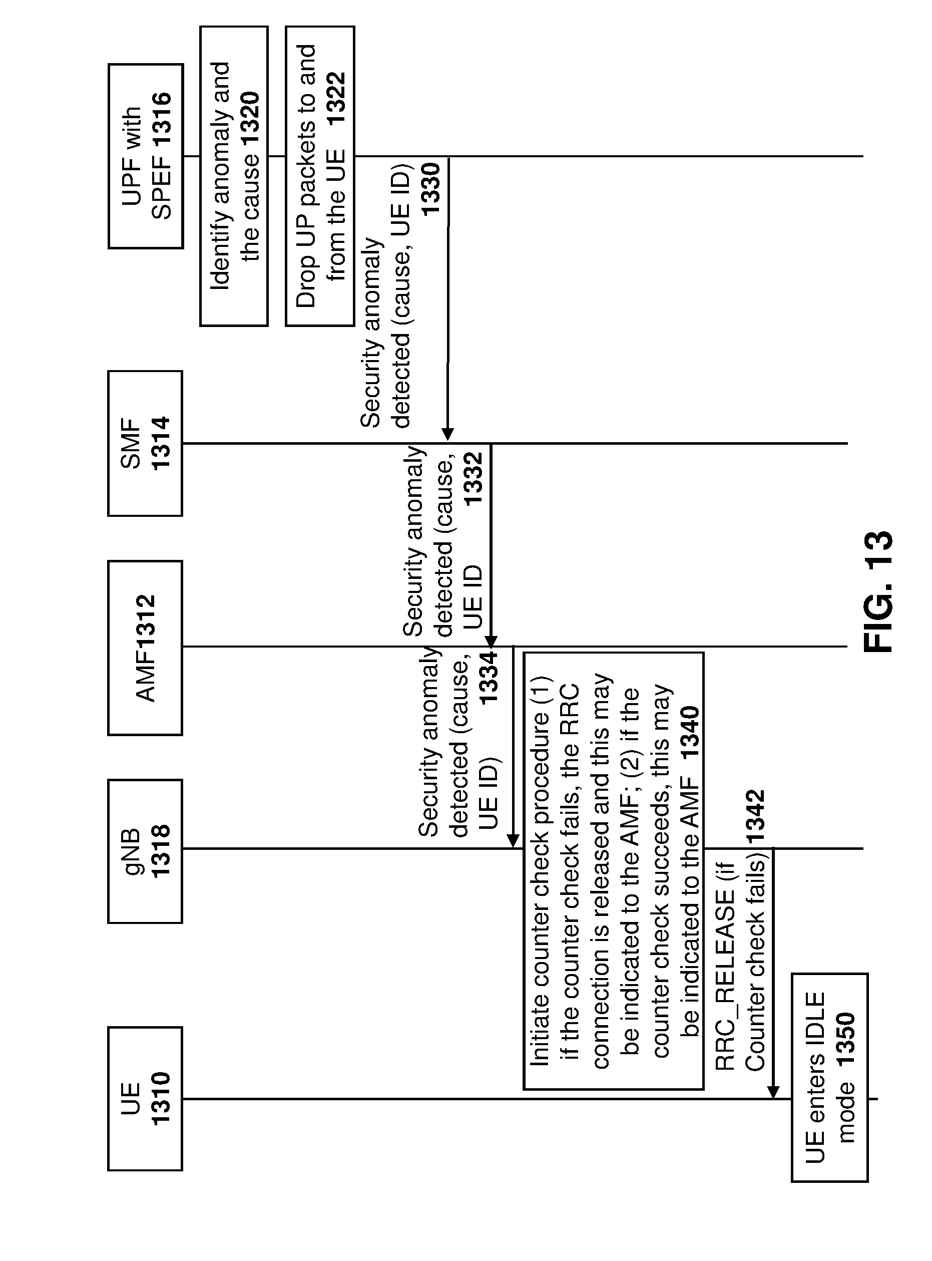
D00014

D00015
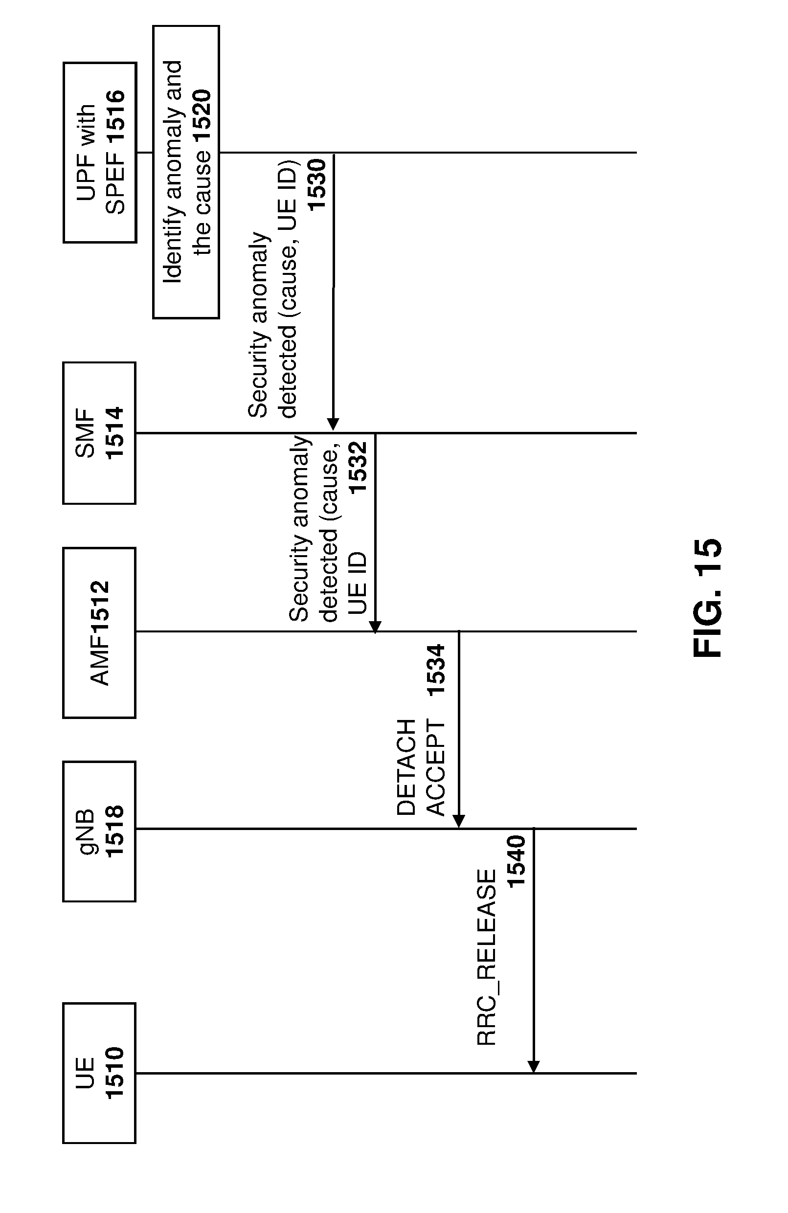
D00016
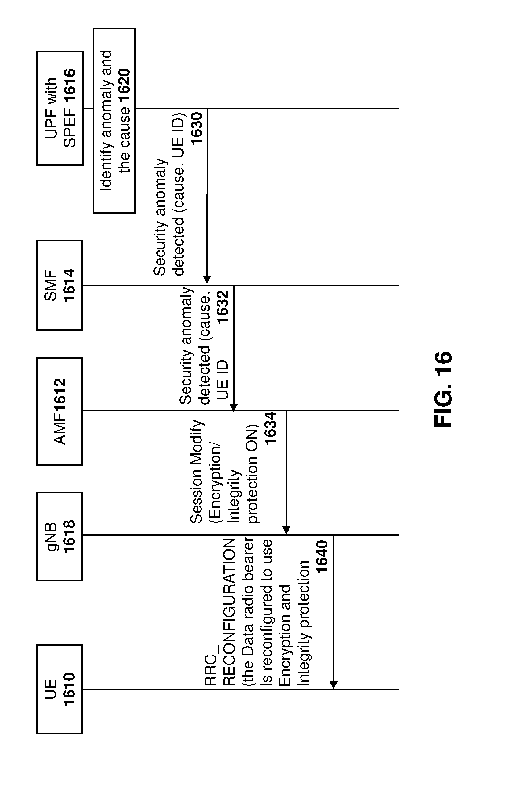
D00017
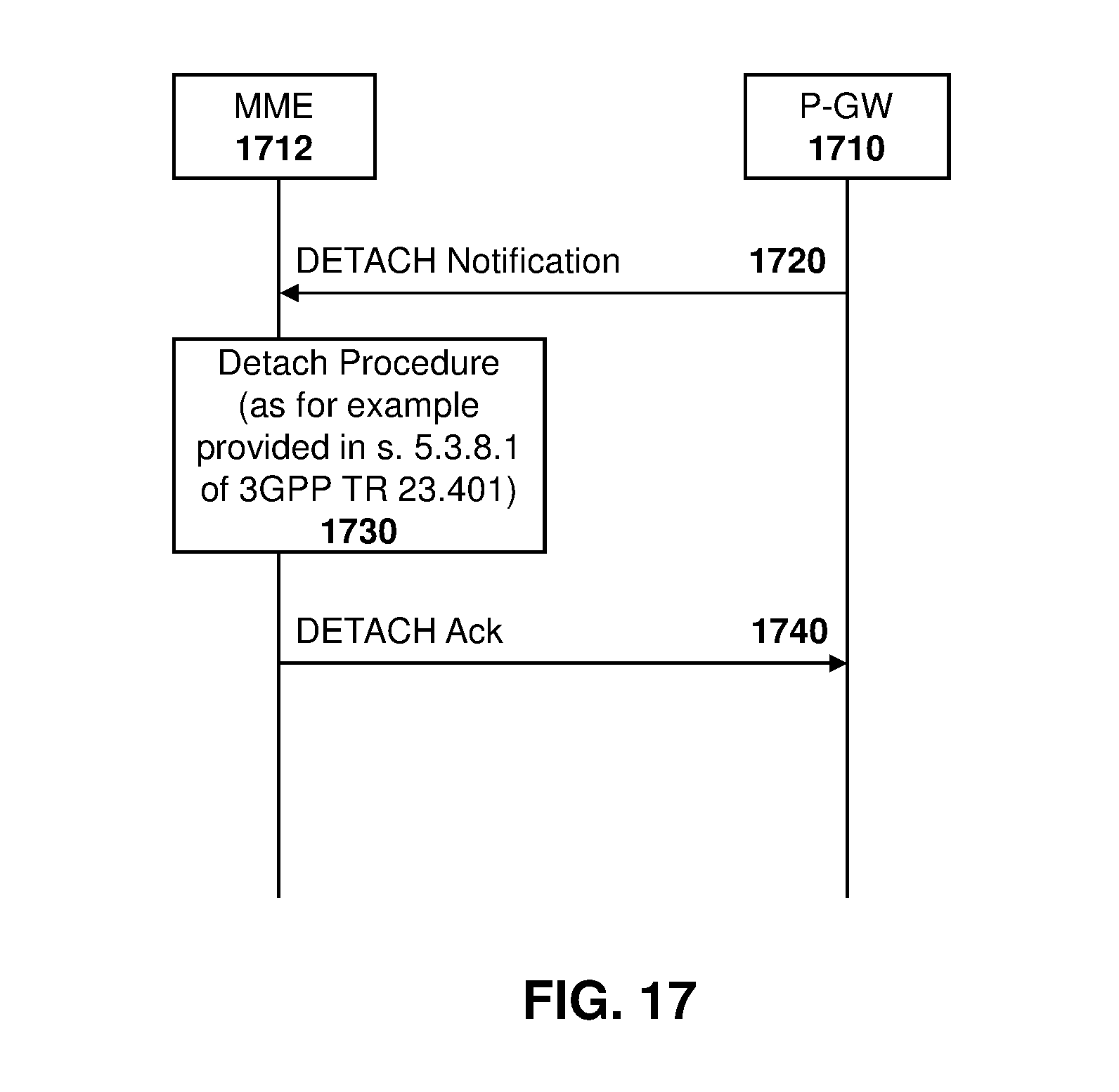
D00018
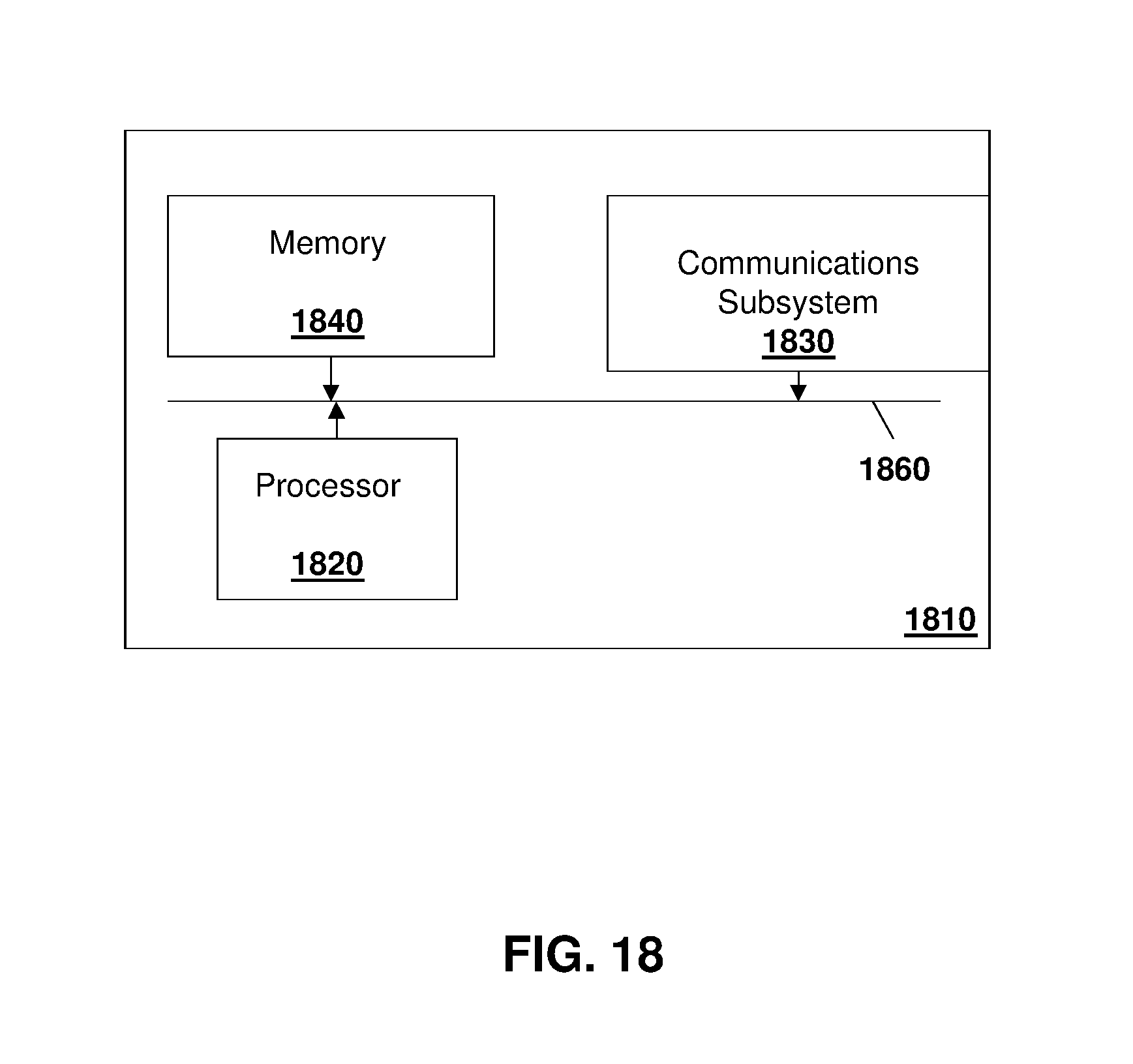
D00019
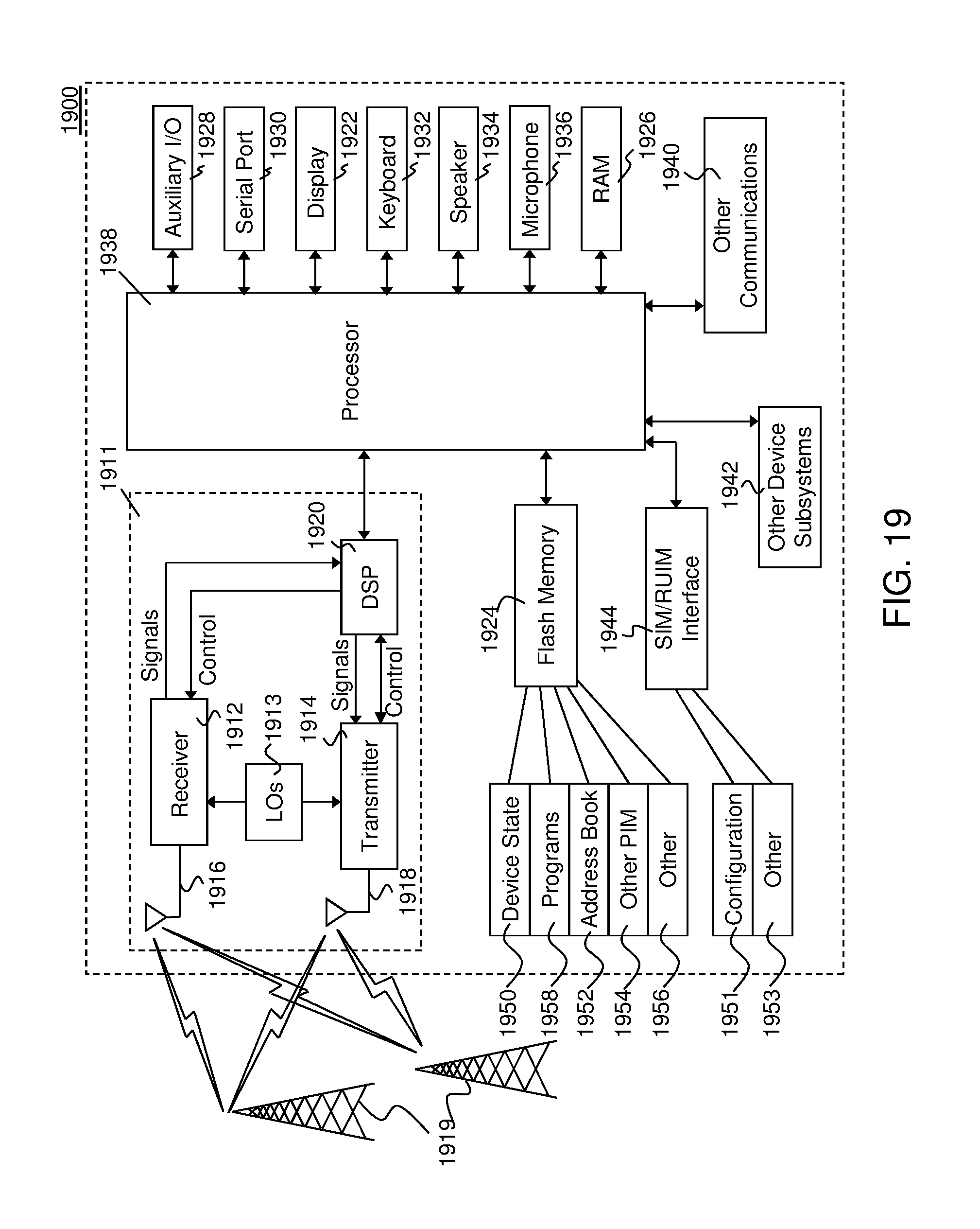
P00001
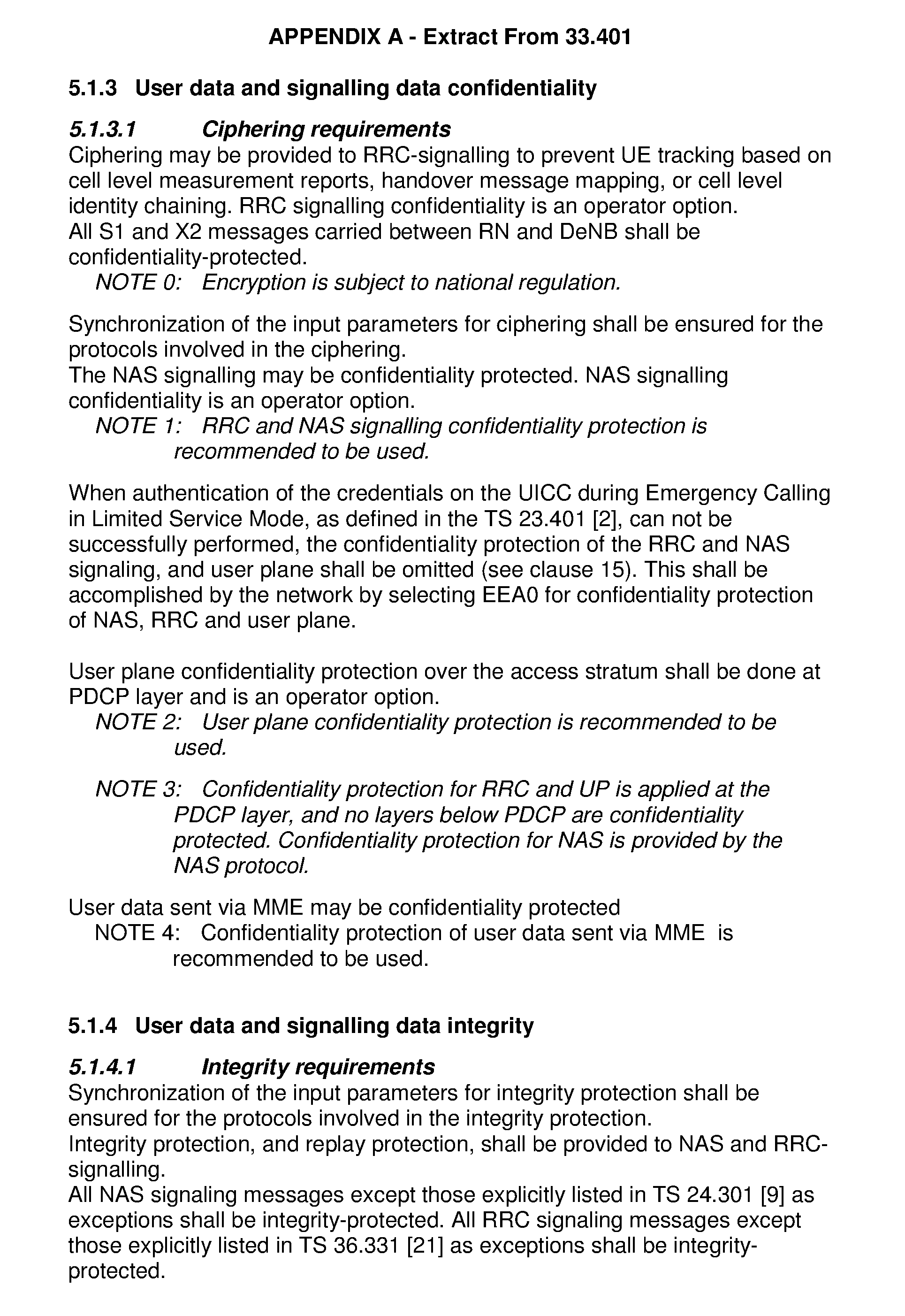
P00002
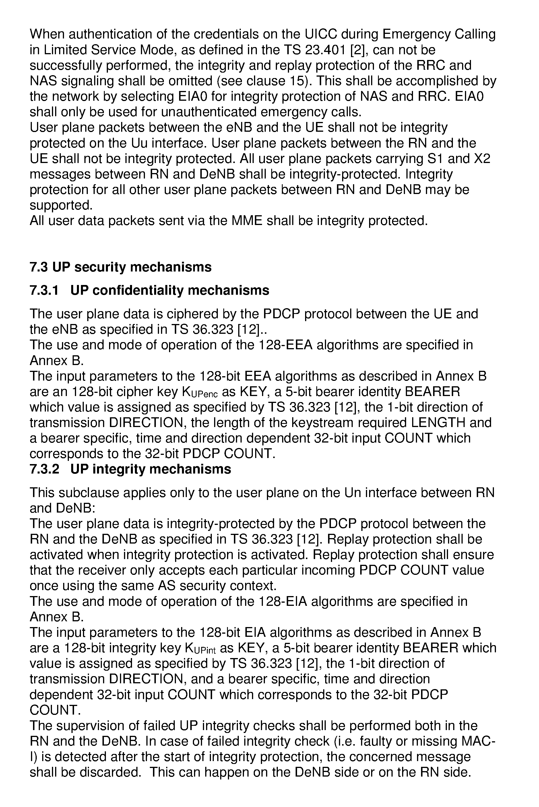
P00003
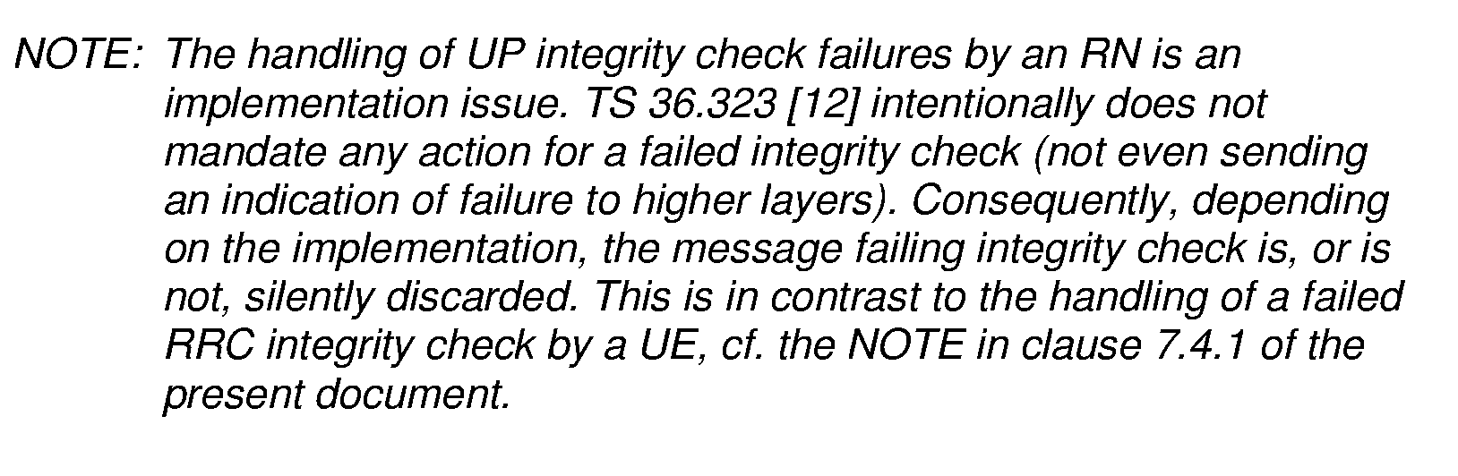
P00004
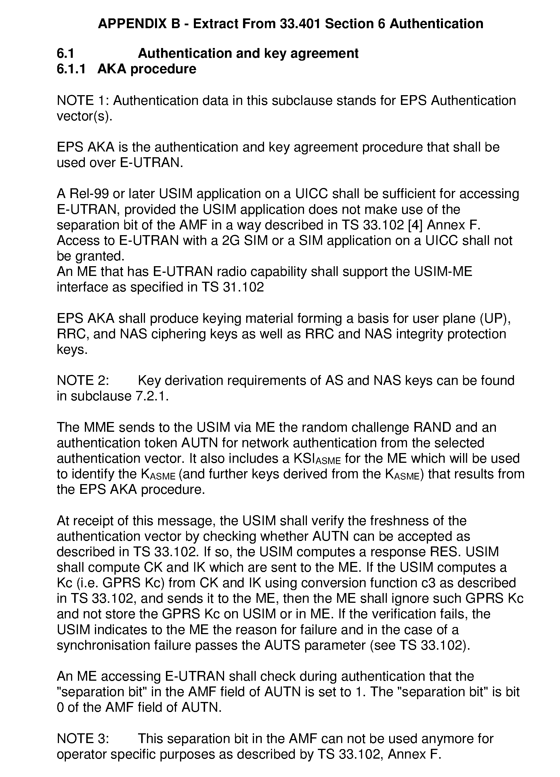
P00005
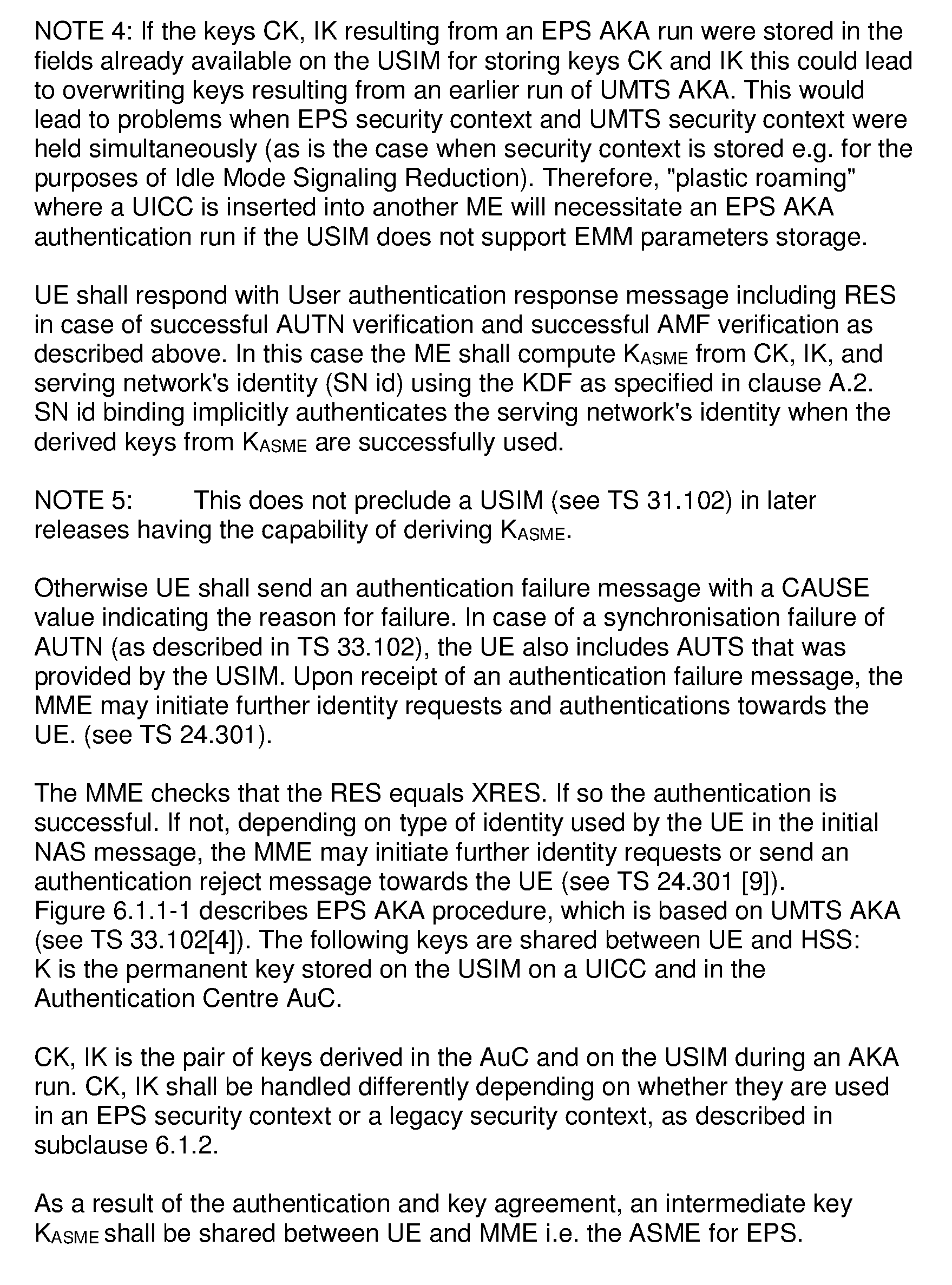
P00006
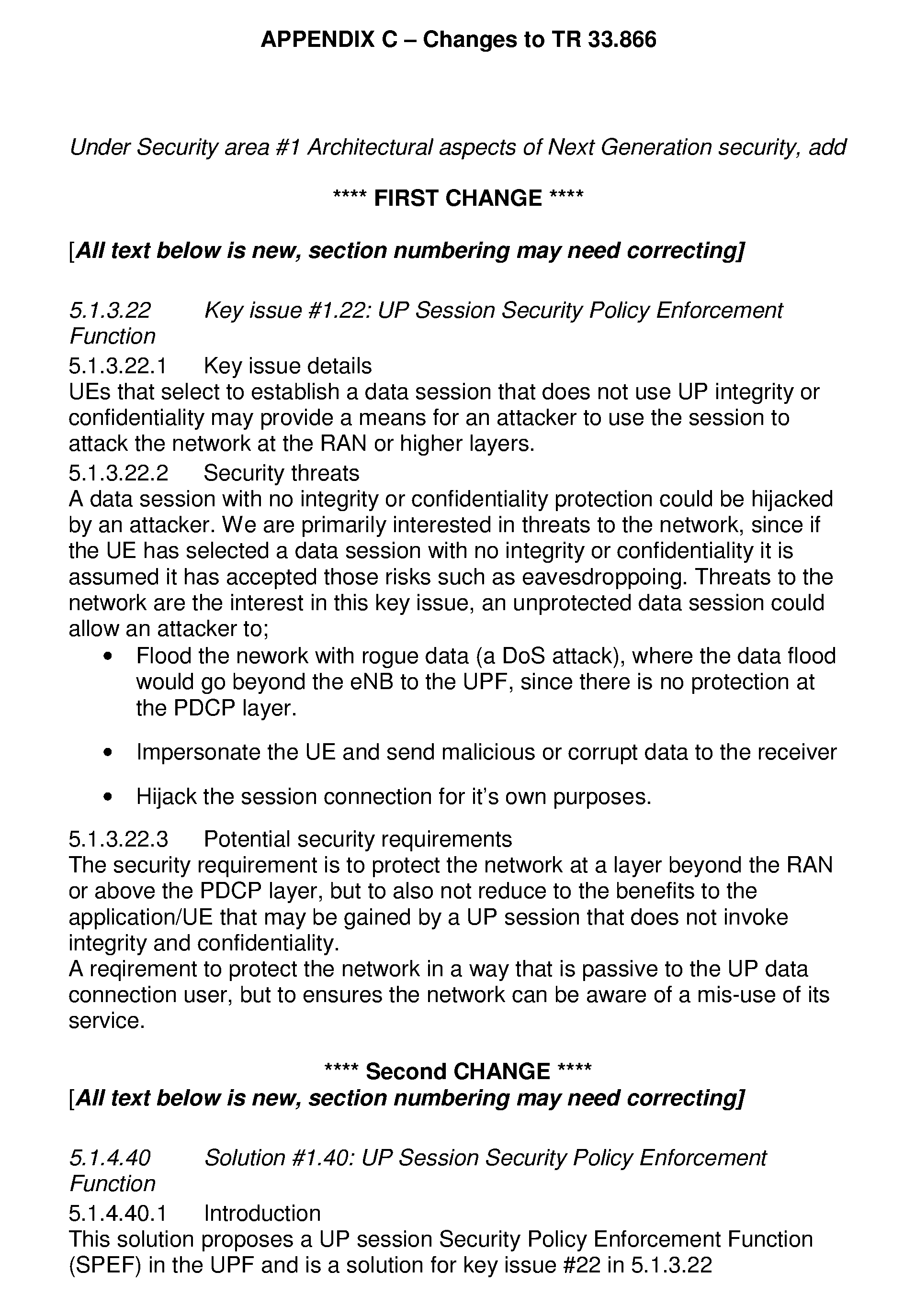
P00007
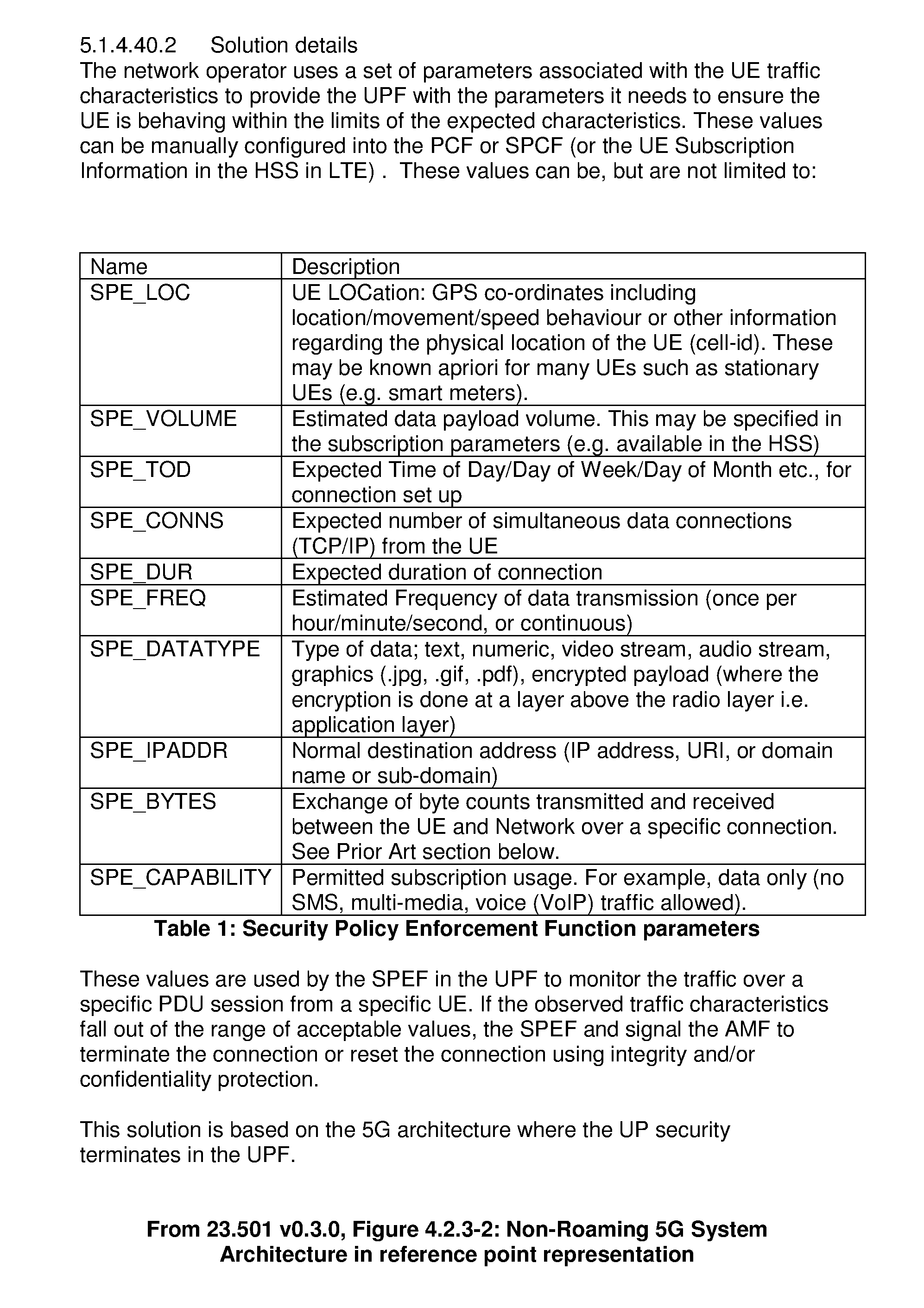
P00008
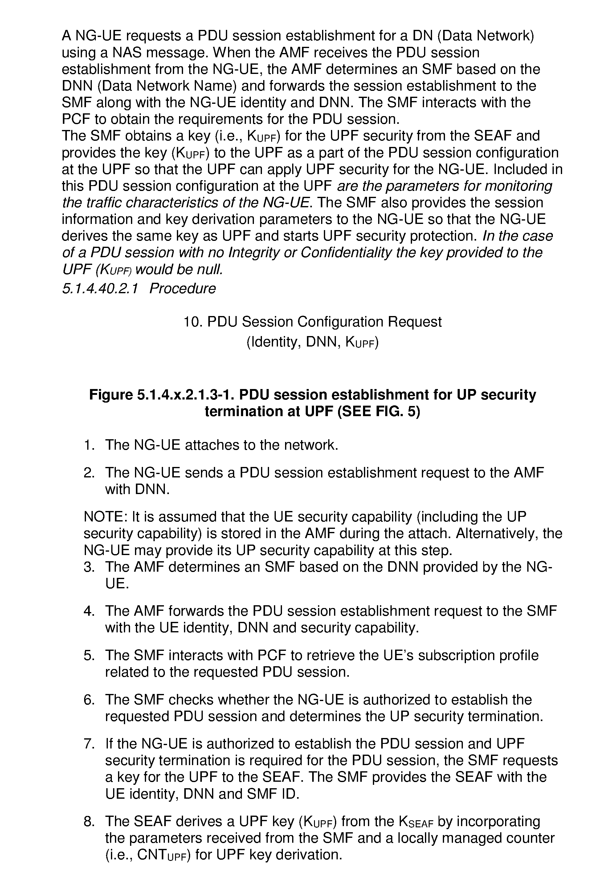
P00009

P00010
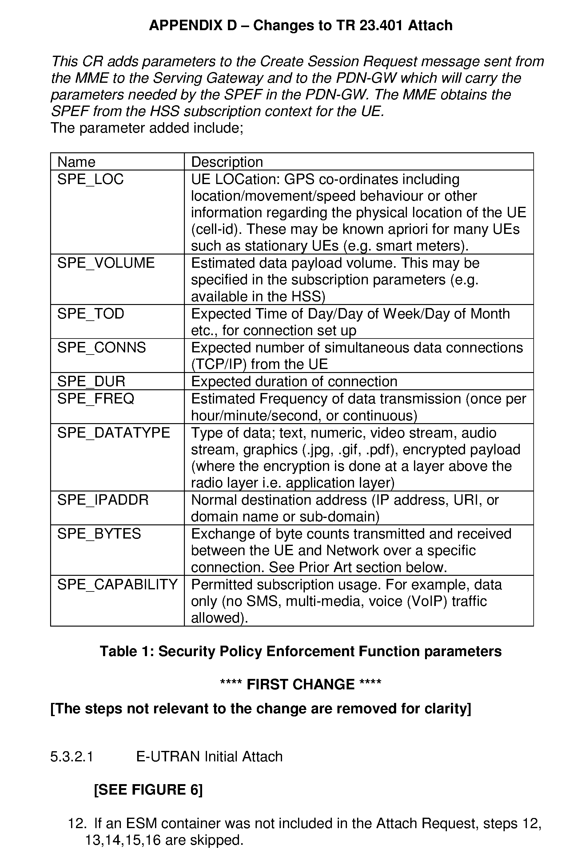
P00011
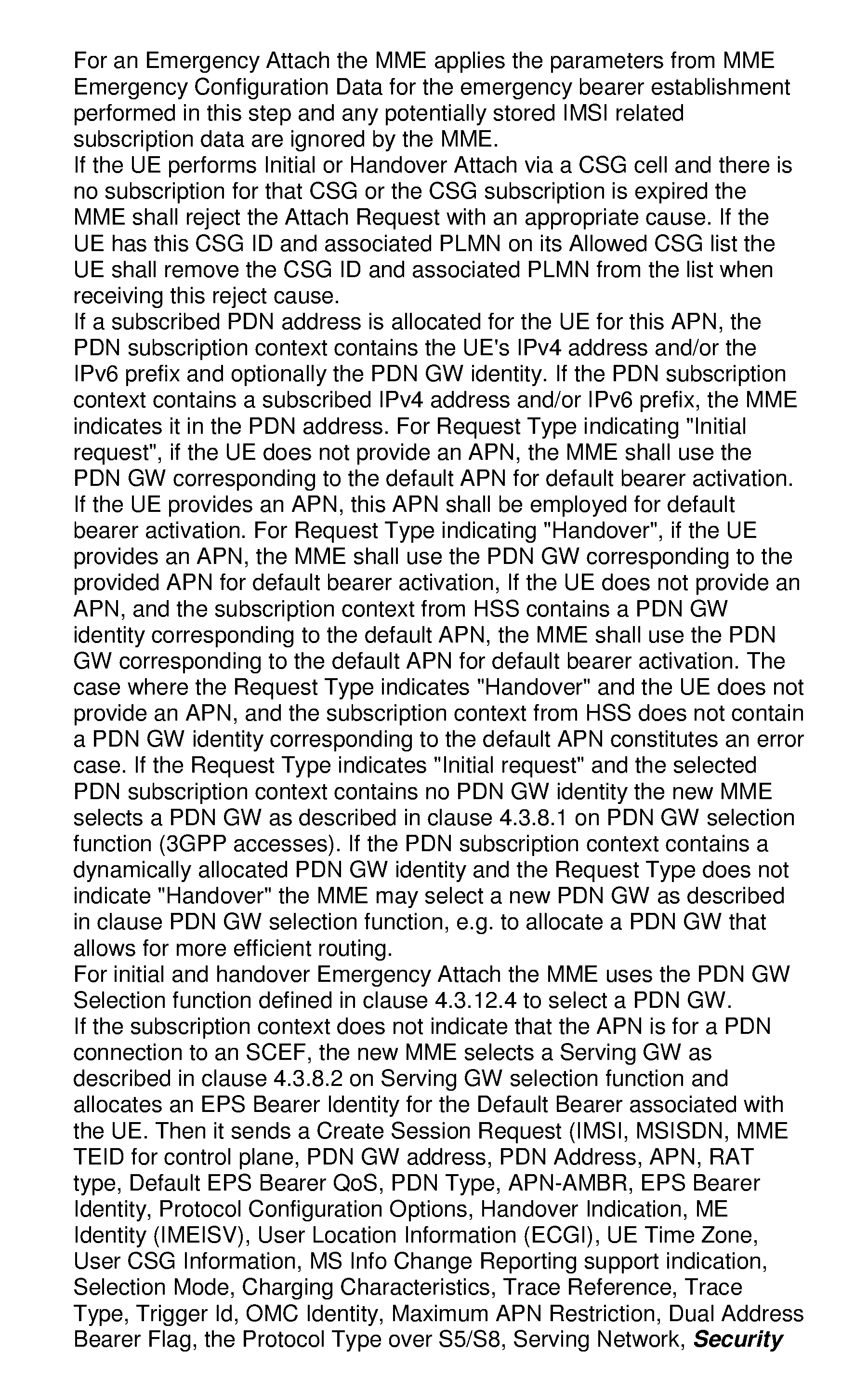
P00012
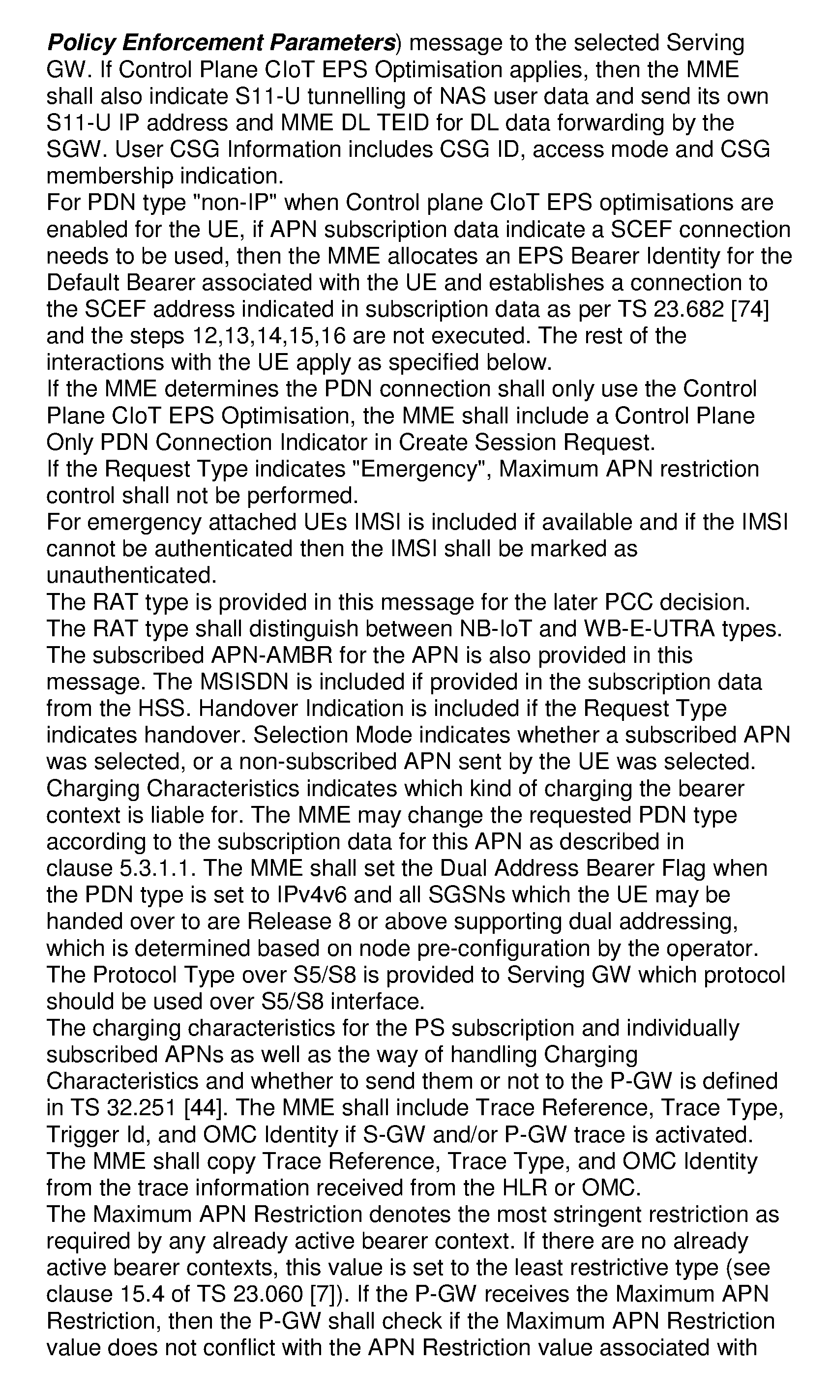
P00013
P00014
P00015
P00016
XML
uspto.report is an independent third-party trademark research tool that is not affiliated, endorsed, or sponsored by the United States Patent and Trademark Office (USPTO) or any other governmental organization. The information provided by uspto.report is based on publicly available data at the time of writing and is intended for informational purposes only.
While we strive to provide accurate and up-to-date information, we do not guarantee the accuracy, completeness, reliability, or suitability of the information displayed on this site. The use of this site is at your own risk. Any reliance you place on such information is therefore strictly at your own risk.
All official trademark data, including owner information, should be verified by visiting the official USPTO website at www.uspto.gov. This site is not intended to replace professional legal advice and should not be used as a substitute for consulting with a legal professional who is knowledgeable about trademark law.