Electric Generator
BATHON; Tobias Siegfried ; et al.
U.S. patent application number 16/080049 was filed with the patent office on 2019-02-28 for electric generator. The applicant listed for this patent is GE Jenbacher GmbH & Co. OG. Invention is credited to Freddy Eduardo ALCAZAR BARRIENTOS, Tobias Siegfried BATHON, Logeswaran PARTHEEBAN.
| Application Number | 20190068096 16/080049 |
| Document ID | / |
| Family ID | 58401577 |
| Filed Date | 2019-02-28 |
| United States Patent Application | 20190068096 |
| Kind Code | A1 |
| BATHON; Tobias Siegfried ; et al. | February 28, 2019 |
ELECTRIC GENERATOR
Abstract
An electric rotating machine having a stator and a rotor, wherein the rotor is provided with rotor windings connected to electric contacts to carry a field current. A control device is provided to adjust the field current carried by the rotor windings. At least one sensor is provided to give information about the temperature at the location of the at least one sensor. The at least one sensor is located on or embedded in the rotor windings, and the at least one sensor is connected to the control device such that the control device is able to read the information given by the at least one sensor. The control device is further arranged to adjust the field current carried by the rotor windings and/or power output or power input of the electric rotating machine based on the information given by the at least one sensor.
| Inventors: | BATHON; Tobias Siegfried; (Jenbach, Tirol, AT) ; ALCAZAR BARRIENTOS; Freddy Eduardo; (Jenbach, Tirol, AT) ; PARTHEEBAN; Logeswaran; (Bangalore, IN) | ||||||||||
| Applicant: |
|
||||||||||
|---|---|---|---|---|---|---|---|---|---|---|---|
| Family ID: | 58401577 | ||||||||||
| Appl. No.: | 16/080049 | ||||||||||
| Filed: | March 22, 2017 | ||||||||||
| PCT Filed: | March 22, 2017 | ||||||||||
| PCT NO: | PCT/EP2017/056889 | ||||||||||
| 371 Date: | August 27, 2018 |
| Current U.S. Class: | 1/1 |
| Current CPC Class: | H02P 2101/15 20150115; Y02E 10/72 20130101; H02P 2101/10 20150115; H02P 9/10 20130101; F03D 9/25 20160501; H02P 9/107 20130101 |
| International Class: | H02P 9/10 20060101 H02P009/10; F03D 9/25 20060101 F03D009/25 |
Foreign Application Data
| Date | Code | Application Number |
|---|---|---|
| Mar 24, 2016 | AT | A50242/2016 |
Claims
1. An electric rotating machine comprising: a stator and a rotor, wherein the rotor is provided with rotor windings connected to electric contacts to carry a field current; a control device provided to adjust the field current carried by the rotor windings; and at least one sensor to give information about a temperature at a location of the at least one sensor, the at least one sensor located on or embedded in the rotor windings, and the at least one sensor connected to the control device such that the control device is operable to read the information given by the at least one sensor; wherein the control device is further arranged to adjust the field current carried by the rotor windings, and/or power output or power input of the electric rotating machine based on the information given by the at least one sensor.
2. The electric rotating machine according to claim 1, wherein the control device is arranged to reduce the field current carried by the rotor windings and/or power output or power input of the electric rotating machine if the temperature at the location of the at least one sensor reaches or exceeds a given threshold.
3. The electric rotating machine according to claim 1, wherein the at least one sensor is a plurality of sensors, the plurality of sensors arranged at different positions on or in the rotor windings.
4. The electric rotating machine according to claim 1, wherein the at least one sensor is of a passive type, wherein there is provided an emitter arranged to send a frequency signal, the frequency signal changed at the position of the at least one sensor depending on the temperature at the location of the at least one sensor, and wherein the at least one sensor is arranged to retransmit the changed frequency signal.
5. The electric rotating machine according to claim 1, wherein the connection between the control device and the at least one sensor comprises slip rings and wires leading to the slip rings.
6. The electric rotating machine according to claim 1, wherein the electric machine is an electric generator.
7. A genset comprising: an electric generator and a prime mover connected by a shaft to the electric generator to transfer torque, wherein the electric generator or the prime mover is an electric rotating machine according to claim 1.
Description
TECHNOLOGY FIELD
[0001] This disclosure relates to an electric rotating machine with the features of the preamble of claim 1 and a genset comprising such an electric rotating machine.
BACKGROUND
[0002] Electric rotating machine refers to both generators and motors.
[0003] It is known that generator rotor windings can overheat because of various generator operation conditions and failure modes. If the temperature gets too high, insulation between the rotor windings can deteriorate leading to electric shortages.
[0004] The rotor of the electric rotating machine can be considered of any art such as salient pole, round rotor, squirrel cage, cylindrical, etc.
[0005] Prior art concentrates on:
[0006] estimating rotor temperature by measurement of rotor current, and controlling the temperature by varying the output load of the generator.
[0007] U.S. Pat. No. 8,967,857 B2 shows a temperature detection device that detects a temperature of a rotor of a motor by measuring rotor current.
[0008] U.S. Pat. No. 3,358,208 shows a method for controlling temperature rise in rotor windings by varying the output load.
[0009] US 2012/0133313 A1 describes a generator provided with a rotor temperature rise estimation device.
[0010] U.S. Pat. No. 8,482,238 B2 describes a system and method for estimating a generator rotor temperature in an electric drive machine.
SUMMARY OF THE DISCLOSURE
[0011] A prime mover is defined as the source of mechanical torque to an electric generator, coming from any source such as a gas turbine, reciprocating engine (diesel or gas), hydro turbine, wind turbine, and all other generation sources. A genset is comprised by an electric generator and a prime mover connected by a shaft to transfer torque.
[0012] It is an object of the disclosure to provide an electric rotating machine and a genset where it is possible to control the temperature of the rotor windings more reliably.
[0013] This object is being accomplished by an electric generator having the features of claim 1 and a genset comprising such an electric generator. Advantageous embodiments of the disclosure are defined in the dependent claims.
[0014] This disclosure differs from the prior art by:
[0015] measuring directly the rotor windings temperature by using temperature sensors arranged or in the rotor windings; and
[0016] controlling rotor windings temperature in reaction to the measured temperatures by varying the field current and/or output power.
[0017] It can be provided that the control device is being arranged to reduce the field current carried by the rotor windings and/or power output of the electric generator if the temperature at the location of the at least one sensor reaches or exceeds a given threshold. In this way overheating of the rotor can be avoided. Any one of these measures leads to a decrease in temperature of the rotor windings and thus avoids overheating.
[0018] It can be provided that there is a plurality of sensors, the sensors of the plurality being arranged at different positions on or in the rotor windings. The sensors can be placed at so-called hotspots. These are positions where temperature maxima are to be expected.
[0019] It can be provided that the at least one sensor is of a passive type, and wherein there is provided an emitter arranged to send a frequency signal, the frequency signal being changed at the position of the at least one sensor depending on the temperature at the location of the at least one sensor, and wherein the at least sensor is arranged to retransmit the changed frequency signal. No wiring of the sensors is necessary. An example for a sensor of a passive type is a so-called SAW-sensor (surface acoustic wave sensor) which uses and modulates surface acoustic waves to sense physical properties.
[0020] It can be provided that the at least one sensor is of an active type (such as thermocouples, RTDs, etc.).
[0021] It can be provided that the connection between the control device and the at least sensor comprises slip rings and wires leading from the sensors to the slip rings and from the slip rings to the control unit.
[0022] It can be provided that the connection between the control device and the at least sensor comprises at least one passive or active sensor. It can be used together with slip rings, e.g., to transmit the information from the slip rings to the control unit, or without slip rings.
[0023] The control unit can be part of an excitation control system of the electric generator. For a genset, it can be part of an electronic control unit of the genset.
BRIEF DESCRIPTION OF THE DRAWINGS
[0024] Embodiments of the disclosure are shown in FIGS. 1 to 3:
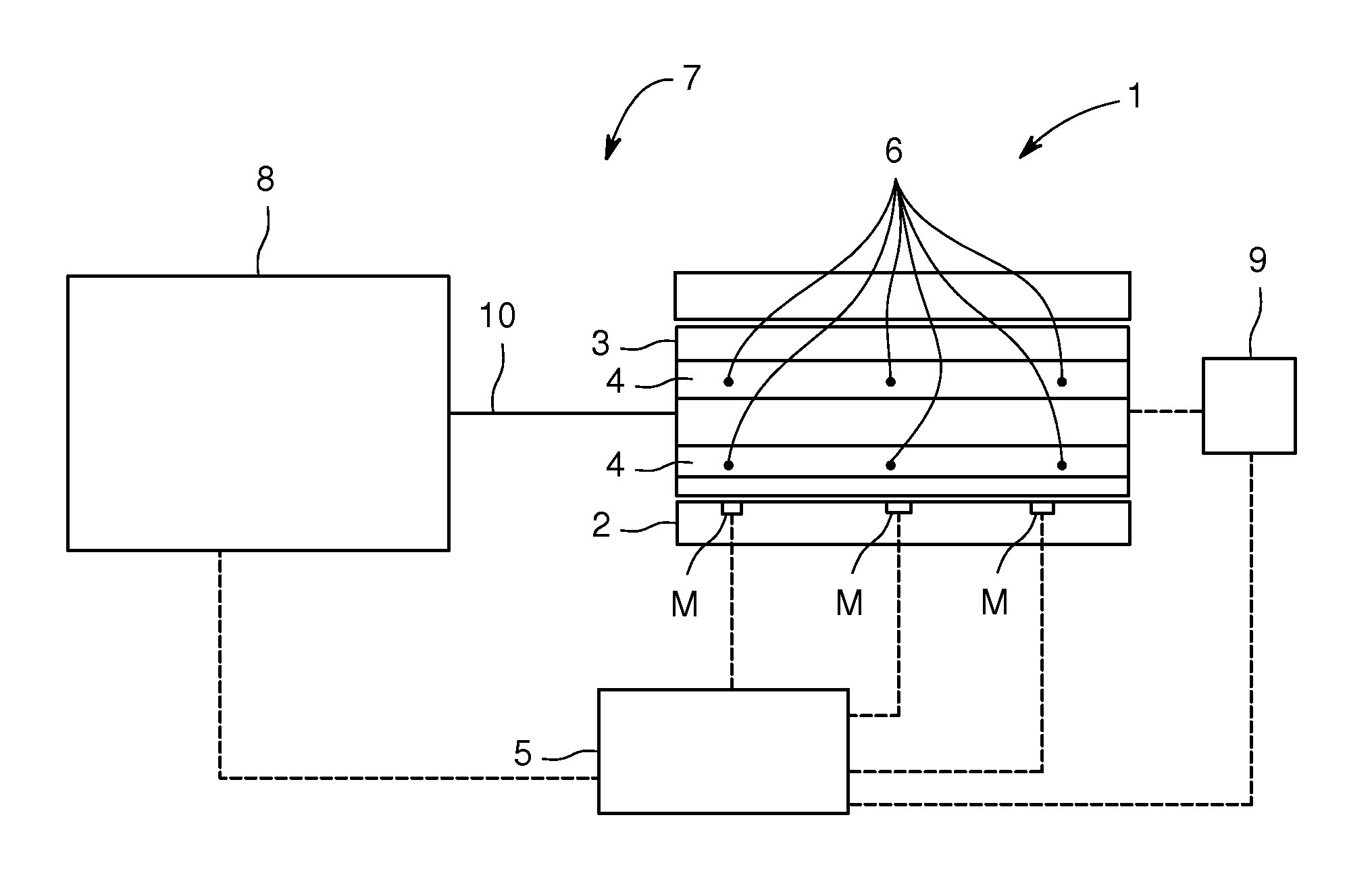
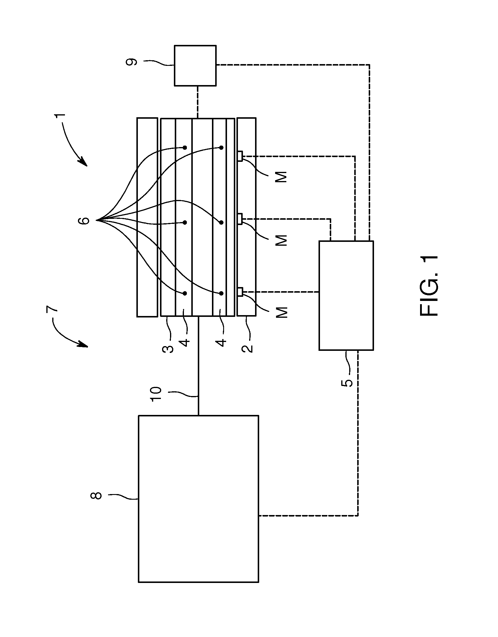
[0025] FIG. 1 shows schematically an embodiment of a genset;
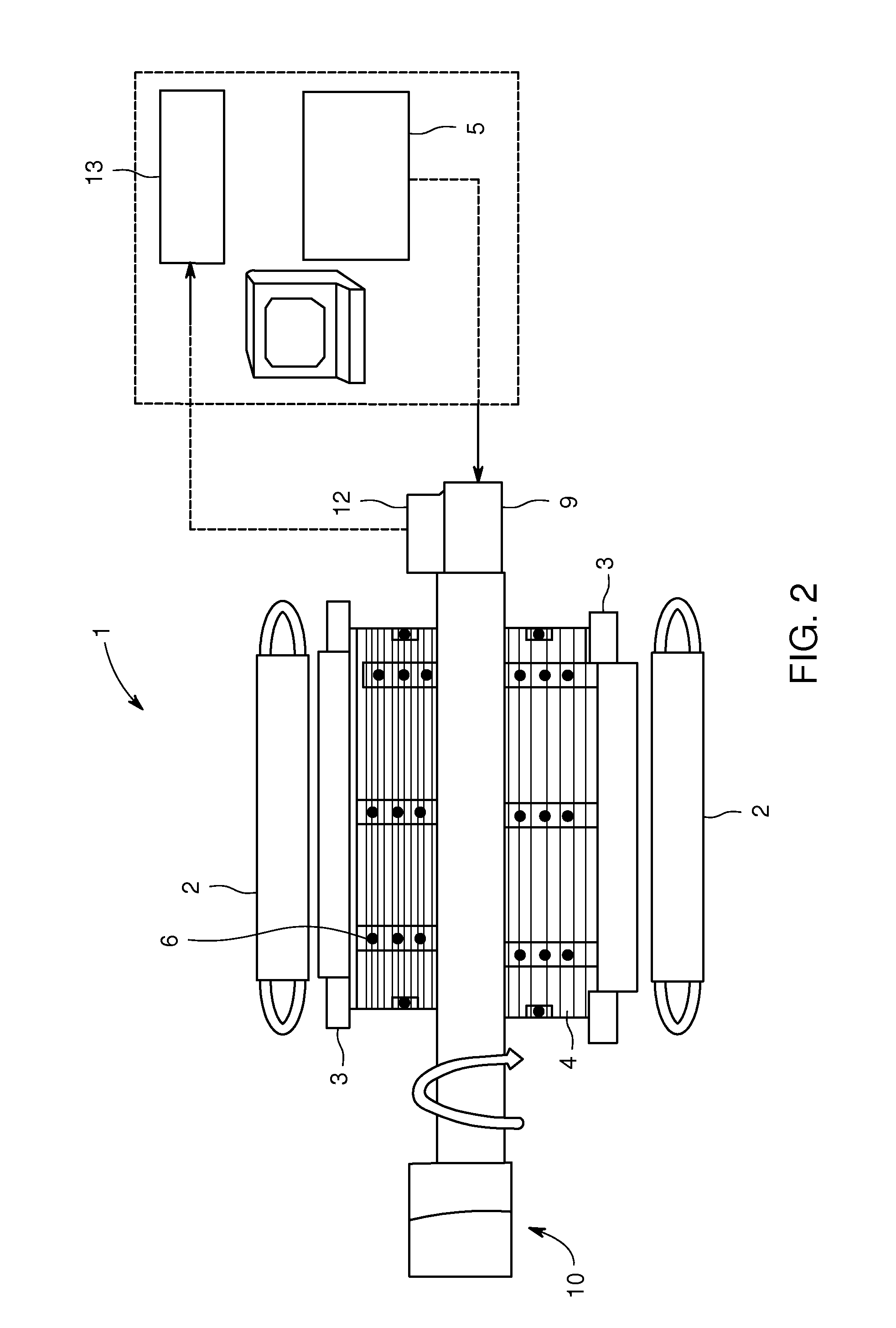
[0026] FIG. 2 shows an electric generator having a stator 2 and a rotor 3; and
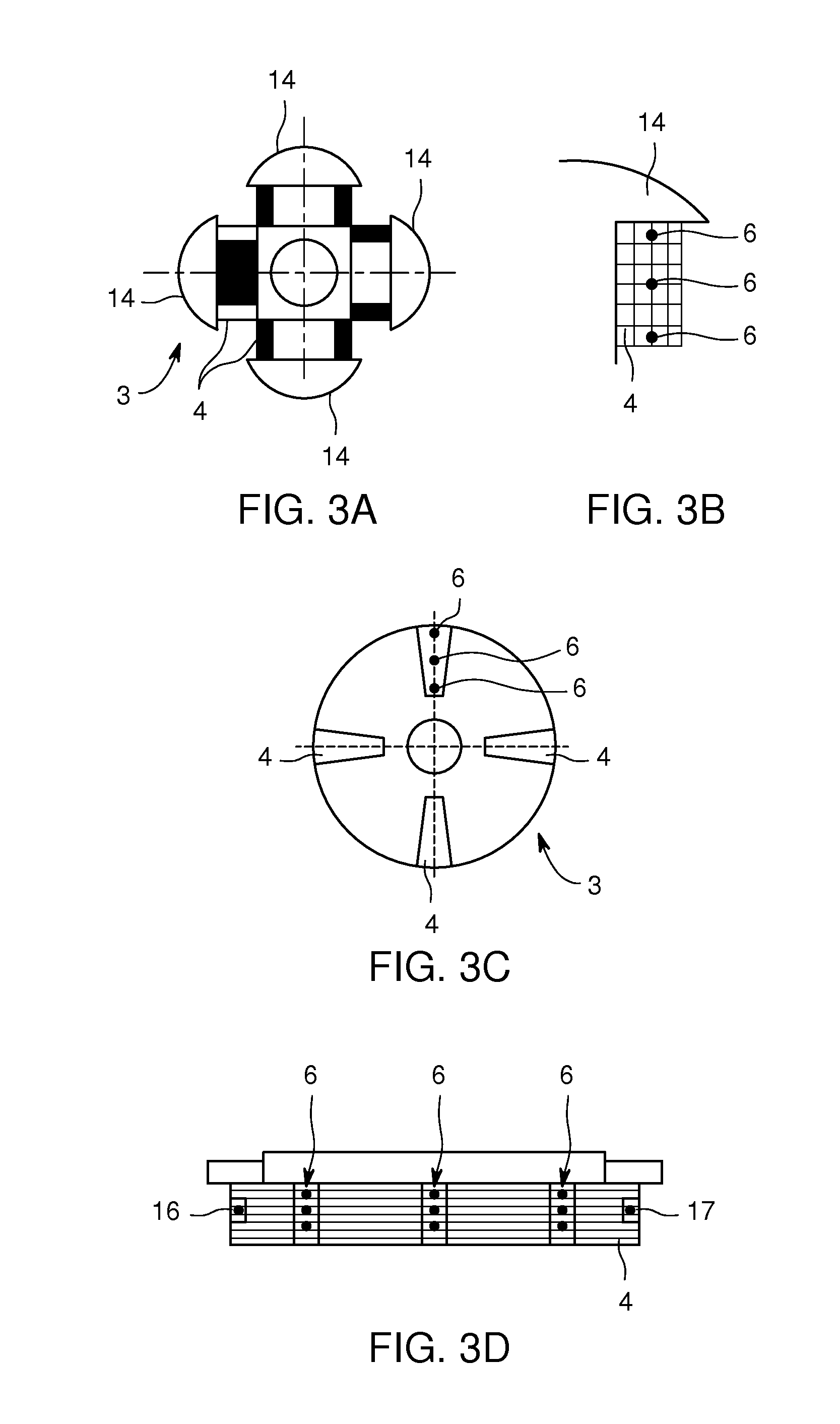
[0027] FIG. 3A, FIG. 3B, FIG. 3C and FIG. 3D show possible placements for the sensors 6 at the top, bottom, or center of a rotor winding 4 for a rotor 3 of the salient pole type (FIGS. 3A, 3B and 3C, FIG. 3B shows a detail of FIG. 3A, and FIG. 3D shows a cross section through the rotor 3 of FIG. 3A) and of the non-salient pole type (FIG. 3C).
DETAILED DESCRIPTION
[0028] FIG. 1 shows schematically an embodiment of a genset 7 having an electric rotating machine 1 in the form of an electric generator and a prime mover 8 (in particular a combustion engine such as a gas or diesel engine having a plurality of pistons arranged movably in combustion cylinders) to drive the electric generator via coupling 10. The electric generator comprises a stator 2 and a rotor 3, the rotor 3 having several rotor windings 4 (two of which are shown in FIG. 1 by way of example). A control unit 5 is arranged to receive information and to send commands as indicated by the dashed lines. In this embodiment the control unit 5 is arranged as an electronic control unit of the complete genset 7.
[0029] In this embodiment a plurality of passive sensors 6 (six of which are shown in FIG. 1 by way of example) is arranged on and within the rotor windings 4. There are provided emitter/receiver-units 11 (three of which are shown in FIG. 1 by way of example) arranged to send a frequency signal upon a command of the control unit 5, the frequency signal being changed at the position of sensors 6 depending on the temperature at the location of the sensors 6. The sensors 6 retransmit the changed frequency signals which can be received by the emitter/receiver-units 11. No wiring of the sensors 6 is necessary.
[0030] If the control unit 5 concludes from the information provided by the sensor 6 via emitter/receiver-units 11 that the temperature at one or several of the locations of the sensors 6 reaches or exceeds a given thresholds it can:
[0031] command the prime mover 8 to reduce driving torque of the rotor 3; and/or
[0032] command an excitation control unit 9 to reduce field current carried by the rotor windings 4
[0033] FIG. 2 shows an electric generator having a stator 2 and a rotor 3 the rotor 3 being provided with rotor windings 4. The rotor 3 can be driven by a prime mover (not shown, e.g., a combustion engine) via coupling 10. A plurality of sensors 6 located at different positions on and in the rotor windings 4 is shown. Control unit 5 can command a decrease of the field current carried by rotor windings 4 to decrease their temperature and/or to decrease output power of the electric generator.
[0034] As noted above, FIG. 3A to 3D show possible placements for the sensors 6 at the top, bottom, or center of a rotor winding 4 for a rotor 3 of the salient pole type (FIGS. 3A, 3B and 3C, FIG. 3B shows a detail of FIG. 3A, here by way of example four poles 14 are shown, FIG. 3D shows a cross section through the rotor 3 of FIG. 3A) and of the non-salient pole type (FIG. 3C).
[0035] In FIG. 3D, the outer left plurality of sensors 6 is arranged at a drive end (DE) side, the centre plurality of sensors 6 is arranged at a core pack and the outer right plurality of sensor 6 is arranged at a non drive end (NDE) core. Reference sign 16 denotes a DE section of winding, reference sign 17 shows an NDE section of winding.
* * * * *
D00000
D00001
D00002
D00003
XML
uspto.report is an independent third-party trademark research tool that is not affiliated, endorsed, or sponsored by the United States Patent and Trademark Office (USPTO) or any other governmental organization. The information provided by uspto.report is based on publicly available data at the time of writing and is intended for informational purposes only.
While we strive to provide accurate and up-to-date information, we do not guarantee the accuracy, completeness, reliability, or suitability of the information displayed on this site. The use of this site is at your own risk. Any reliance you place on such information is therefore strictly at your own risk.
All official trademark data, including owner information, should be verified by visiting the official USPTO website at www.uspto.gov. This site is not intended to replace professional legal advice and should not be used as a substitute for consulting with a legal professional who is knowledgeable about trademark law.