Terminal Frame and Stator Frame
Huang; Yongjian ; et al.
U.S. patent application number 16/109919 was filed with the patent office on 2019-02-28 for terminal frame and stator frame. This patent application is currently assigned to Tyco Electronics (Shanghai) Co. Ltd.. The applicant listed for this patent is Tyco Electronics (Shanghai) Co. Ltd.. Invention is credited to Tongbao Ding, Yongjian Huang, Sheng Li.
| Application Number | 20190068022 16/109919 |
| Document ID | / |
| Family ID | 65321901 |
| Filed Date | 2019-02-28 |


| United States Patent Application | 20190068022 |
| Kind Code | A1 |
| Huang; Yongjian ; et al. | February 28, 2019 |
Terminal Frame and Stator Frame
Abstract
A terminal frame of a stator frame comprises a body adapted to receive a terminal. The body of the terminal frame is also adapted to be mounted to a coil frame of the stator frame in a detachable manner.
| Inventors: | Huang; Yongjian; (Shanghai, CN) ; Ding; Tongbao; (Shanghai, CN) ; Li; Sheng; (Shanghai, CN) | ||||||||||
| Applicant: |
|
||||||||||
|---|---|---|---|---|---|---|---|---|---|---|---|
| Assignee: | Tyco Electronics (Shanghai) Co.
Ltd. Shanghai CN |
||||||||||
| Family ID: | 65321901 | ||||||||||
| Appl. No.: | 16/109919 | ||||||||||
| Filed: | August 23, 2018 |
| Current U.S. Class: | 1/1 |
| Current CPC Class: | H02K 5/225 20130101; H02K 3/522 20130101 |
| International Class: | H02K 5/22 20060101 H02K005/22 |
Foreign Application Data
| Date | Code | Application Number |
|---|---|---|
| Aug 24, 2017 | CN | 201710733596.X |
| Oct 9, 2017 | CN | 201710929695.5 |
Claims
1. A terminal frame of a stator frame, comprising: a body adapted to receive a terminal and adapted to be mounted to a coil frame of the stator frame in a detachable manner.
2. The terminal frame of claim 1, wherein the body is adapted to be installed and locked in the coil frame in a snap-fitting manner.
3. The terminal frame of claim 2, wherein the body includes a pair of end walls and an inner side wall.
4. The terminal frame of claim 3, wherein an elastic latch is formed on the inner side wall.
5. The terminal frame of claim 4, wherein the elastic latch is adapted to be locked into a slot formed in the coil frame to lock the terminal frame to the coil frame.
6. The terminal frame of claim 5, wherein each of the pair of end walls has a wedge positioning block.
7. The terminal frame of claim 6, wherein the wedge positioning block is adapted to be fit in a wedge positioning slot formed in the coil frame to guide the terminal frame to be correctly inserted into an installation chamber formed on the coil frame.
8. The terminal frame of claim 1, further comprising a plurality of terminal chambers each receiving a terminal.
9. The terminal frame of claim 8, wherein a plurality of wire slots are formed in the inner side wall and an outer side wall of the terminal frame.
10. The terminal frame of claim 9, wherein a plurality of lead ends of a plurality of coils wound on the coil frame are adapted to be pressed into and positioned in the wire slots.
11. The terminal frame of claim 10, wherein, when the terminal is mounted in one of the terminal chambers, the terminal is brought into electrical contact with the lead end of one of the coils.
12. A stator frame, comprising: a coil frame on which a coil is adapted to be wound; and a terminal frame separate from the coil frame and adapted to receive a terminal, the terminal frame adapted to be mounted to the coil frame in a detachable manner.
13. The stator frame of claim 12, wherein an installation chamber is formed on an outer side of the coil frame and the terminal frame is adapted to be installed and locked in the installation chamber in a snap-fitting manner.
14. The stator frame of claim 13, wherein the installation chamber includes a pair of end walls and an inner side wall, a slot is formed in the inner side wall.
15. The stator frame of claim 14, wherein the terminal frame includes a pair of end walls and an inner side wall, an elastic latch is formed on the inner side wall of the terminal frame and is adapted to be locked into the slot of the installation chamber to lock the terminal frame to the coil frame.
16. The stator frame of claim 15, wherein each of the pair of end walls of the installation chamber has a wedge positioning slot and each of the pair of end walls of the terminal frame has a wedge positioning block, the wedge positioning block is adapted to be fit in the wedge positioning slot to guide the terminal frame to be correctly inserted into the installation chamber.
17. The stator frame of claim 16, wherein the terminal frame has a plurality of terminal chambers each receiving a terminal, a plurality of wire slots are formed in the inner side wall and an outer side wall of the terminal frame, a plurality of lead ends of a plurality of coils wound on the coil frame are adapted to be pressed into and positioned in the wire slots, and when the terminal is mounted in one of the terminal chambers, the terminal is brought into electrical contact with the lead end of one of the coils.
18. The stator frame of claim 17, wherein the installation chamber of the coil frame is adapted to receive different types of terminal frames therein.
19. The stator frame of claim 18, wherein the terminal chambers of the different types of terminal frames are different from each other in shape or size.
20. The stator frame of claim 18, wherein the wire slots of the different types of terminal frames are different from each other in shape or size.
Description
CROSS-REFERENCE TO RELATED APPLICATIONS
[0001] This application claims the benefit of the filing date under 35 U.S.C. .sctn. 119(a)-(d) of Chinese Patent Application No. 201710929695.5, filed on Oct. 9, 2017, and Chinese Patent Application No. 201710733596.X, filed on Aug. 24, 2017.
FIELD OF THE INVENTION
[0002] The present invention relates to a motor and, more particularly, to a terminal frame and a stator frame for a motor.
BACKGROUND
[0003] A motor generally comprises a stator, a stator frame mounted in the stator, a coil wound on the stator frame, and a rotor mounted in the stator. When the coil is powered, an electromagnetic force is generated to drive the rotor to rotate. The stator frame is usually made of plastic, and the stator and the rotor are usually made of magnetic conductive material.
[0004] The stator frame generally comprises a coil frame for winding coils and a terminal frame for installing terminals. The stator frame is usually a single molded piece; the coil frame and the terminal frame are molded into a single component. In the process of manufacturing the motor, the stator frame is first pressed into the stator. Then, a wire, such as an enameled wire, is wound on the coil frame to form a coil. Lead ends of the coil are then pressed into wire slots formed in the terminal frame. Lastly, terminals are pressed into terminal chambers formed in the terminal frame to electrically connect the lead ends of the coil.
[0005] There are many different types of terminals, such as a MAGMATE type of terminal and a SIAMEZE type of terminal, and many different types of wires known in the art. In order to cooperate with different types of terminals and different types of wires, it is necessary to provide different types of terminal frames with different shapes or dimensions of terminal chambers and wire slots. Because the coil frame and the terminal frame of the stator frame is integrated together, the whole stator frame has to be replaced when it is necessary to replace different types of terminals or different types of wires. For example, if the terminal frame is damaged during the process of pressing the lead ends into the wire slots or pressing the terminals into the terminal chambers, the whole stator frame including the coil frame and the terminal frame must be replaced, which leads to serious waste and increased cost.
SUMMARY
[0006] A terminal frame of a stator frame comprises a body adapted to receive a terminal. The body of the terminal frame is also adapted to be mounted to a coil frame of the stator frame in a detachable manner.
BRIEF DESCRIPTION OF THE DRAWINGS
[0007] The invention will now be described by way of example with reference to the accompanying Figures, of which:
[0008] FIG. 1 is a perspective view of a stator frame according to an embodiment with a stator and a coil;
[0009] FIG. 2 is a perspective view of the stator frame of FIG. 1 with a terminal frame of the stator frame not mounted to a coil frame of the stator frame;
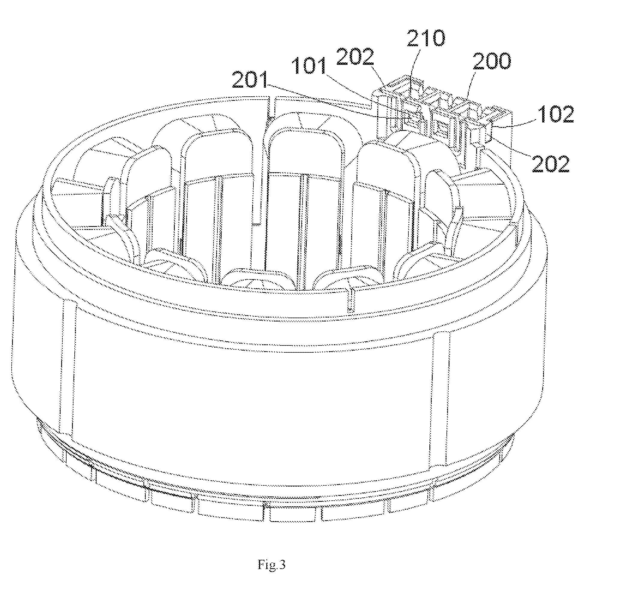
[0010] FIG. 3 is a perspective view of the stator frame of FIG. 1, the stator, and the coil with the terminal frame mounted in the coil frame;
[0011] FIG. 4 is a perspective view of a stator frame according to another embodiment with the stator and the coil;
[0012] FIG. 5 is a perspective view of the stator frame of FIG. 4 with a terminal frame of the stator frame not mounted to a coil frame of the stator frame; and
[0013] FIG. 6 is a perspective view of the stator frame of FIG. 4, the stator, and the coil with the terminal frame mounted in the coil frame.
DETAILED DESCRIPTION OF THE EMBODIMENT(S)
[0014] Embodiments of the present invention will be described hereinafter in detail with reference to the attached drawings, wherein like reference numerals refer to the like elements. The present invention may, however, be embodied in many different forms and should not be construed as being limited to the embodiments set forth herein; rather, these embodiments are provided so that the disclosure will be thorough and complete and will fully convey the concept of the invention to those skilled in the art.
[0015] A stator frame according to an embodiment of the invention is shown in FIGS. 1-3. The stator frame comprises a coil frame 100 and a terminal frame 200. A coil 300 is wound on the coil frame 100. A terminal is mounted in a terminal chamber 210 formed in the terminal frame 200. In the shown embodiment, the stator frame is mounted in a stator 10.
[0016] As shown in FIGS. 1-3, the terminal frame 200 is a component separated from the coil frame 100 and adapted to be mounted to the coil frame 100 in a detachable manner. An installation chamber 110 is formed on an outer side of the coil frame 100 and the terminal frame 200 is adapted to be installed and locked in the installation chamber 110 in a snap-fitting manner.
[0017] The installation chamber 110, as shown in FIGS. 1-3, includes a pair of end walls 111, 112, an inner side wall 113, an outer side wall 114, and a bottom wall 115. A slot 101 is formed in the inner side wall 113 of the installation chamber 110. The terminal frame 200 is adapted to be inserted into the installation chamber 110 through a top opening of the installation chamber 110.
[0018] The terminal frame 200, as shown in FIGS. 1-3, is a body including a pair of end walls 211, 212, an inner side wall 213, and an outer side wall 214. An elastic latch 201 is formed on the inner side wall 213 of the terminal frame 200. The elastic latch 201 of the terminal frame 200 is adapted to be locked into the slot 101 of the installation chamber 110, so as to lock the terminal frame 200 to the coil frame 100.
[0019] As shown in FIGS. 1-3, a wedge positioning slot 102 is formed in each end wall 111, 112 of the installation chamber 110. A wedge positioning block 202 is formed on each end wall 211, 212 of the terminal frame 200. The wedge positioning block 202 is adapted to be fit in the wedge positioning slot 102, so as to guide the terminal frame 200 to be correctly inserted into the installation chamber 110.
[0020] In the embodiment shown in FIGS. 1-3, a plurality of terminal chambers 210 are formed in the terminal frame 200, and a plurality of terminals are adapted to be mounted in the plurality of terminal chambers 210, respectively. As shown in FIG. 2, a plurality of wire slots 220 are formed in the inner side wall 213 and the outer side wall 214 of the terminal frame 200. Lead ends of coils 300 wound on the coil frame 100 are adapted to be pressed into and positioned in the wire slots 220, respectively. When the terminal is mounted in the terminal chamber 210, the terminal is brought into electrical contact with the lead end of the coil 300 and is electrically connected to the coil 300.
[0021] The installation chamber 110 of the coil frame 100 is adapted to receive different types of terminal frames 200, 200' therein. For example, FIGS. 4-6 shows another type of terminal frame 200', which is different from the terminal frame 200 of FIGS. 1-3, mounted in the installation chamber 110 of the coil frame 100.
[0022] In the shown exemplary embodiment, the terminal frame 200 shown in FIGS. 1-3 is a MAGMATE type of terminal frame adapted to receive a MAGMATE type of terminal. The terminal frame 200' shown in FIGS. 4-6 is a SIAMEZE type of terminal frame adapted to receive a SIAMEZE type of terminal. The terminal chamber 210 of the terminal frame 200 is different from the terminal chamber 210' of the terminal frame 200' in shape or size. The wire slot 220 of the terminal frame 200 is different from the wire slot 220' of the terminal frame 200' in shape or size.
[0023] In the stator frame of the embodiments shown in FIGS. 1-6, the terminal frame 200, 200' is an independent component separated from the coil frame 100. Thereby, when different types of terminals or different types of wires must be replaced, or when the terminal frame 200, 200' is damaged during pressing wires or terminals into the terminal frame 200, 200', only the terminal frame 200, 200' must be replaced and it is unnecessary to replace the whole stator frame, thus saving cost.
* * * * *
D00000
D00001
D00002
D00003
D00004
D00005
D00006
XML
uspto.report is an independent third-party trademark research tool that is not affiliated, endorsed, or sponsored by the United States Patent and Trademark Office (USPTO) or any other governmental organization. The information provided by uspto.report is based on publicly available data at the time of writing and is intended for informational purposes only.
While we strive to provide accurate and up-to-date information, we do not guarantee the accuracy, completeness, reliability, or suitability of the information displayed on this site. The use of this site is at your own risk. Any reliance you place on such information is therefore strictly at your own risk.
All official trademark data, including owner information, should be verified by visiting the official USPTO website at www.uspto.gov. This site is not intended to replace professional legal advice and should not be used as a substitute for consulting with a legal professional who is knowledgeable about trademark law.