Methods of Using an Imaging Apparatus in Augmented Reality, in Medical Imaging and Nonmedical Imaging
Vogel; Richard ; et al.
U.S. patent application number 16/116211 was filed with the patent office on 2019-02-28 for methods of using an imaging apparatus in augmented reality, in medical imaging and nonmedical imaging. The applicant listed for this patent is DermaGenesis LLC. Invention is credited to Ran Cohen, Alexander Steinberg, Richard Vogel, Tony Xu.
| Application Number | 20190066390 16/116211 |
| Document ID | / |
| Family ID | 65435388 |
| Filed Date | 2019-02-28 |


View All Diagrams
| United States Patent Application | 20190066390 |
| Kind Code | A1 |
| Vogel; Richard ; et al. | February 28, 2019 |
Methods of Using an Imaging Apparatus in Augmented Reality, in Medical Imaging and Nonmedical Imaging
Abstract
With inventive processing making use of surface-reconstruction and capping steps, more imagery acquired by 3C cameras can be put to use in augmented reality applications, especially applications, such as medical reconstruction, in which a certain theoretical ideal fit might be wanted but can be difficult or seemingly impossible to achieve due to highly complex, irregular shapes, perimeters and surfaces involved. The inventive technology is especially useful for ongoing wound measurement and comparative analysis and characterization of a wound over time, as well as working with anatomical reconstruction. The inventive technology also extends to non-medical augmented reality applications, and provides robust data sets representing a range of real-world objects, such as zoo animals, family pets, etc. susceptible of being imaged and stored as robust data sets that provide better verisimilitude when used in gaming or other virtual-world contexts as compared to a raw data set from a camera.
| Inventors: | Vogel; Richard; (Miami, FL) ; Xu; Tony; (Miami, FL) ; Steinberg; Alexander; (Ra'anana, IL) ; Cohen; Ran; (Petah Tikva, IL) | ||||||||||
| Applicant: |
|
||||||||||
|---|---|---|---|---|---|---|---|---|---|---|---|
| Family ID: | 65435388 | ||||||||||
| Appl. No.: | 16/116211 | ||||||||||
| Filed: | August 29, 2018 |
Related U.S. Patent Documents
| Application Number | Filing Date | Patent Number | ||
|---|---|---|---|---|
| 62552090 | Aug 30, 2017 | |||
| Current U.S. Class: | 1/1 |
| Current CPC Class: | G06T 19/006 20130101; G06T 2207/30096 20130101; G06T 2207/30088 20130101; A63F 13/655 20140902; G06T 7/50 20170101; H04N 13/204 20180501; G06T 2207/30196 20130101; G06T 5/005 20130101; G06T 2207/10012 20130101; G06K 9/3233 20130101; G06T 2207/10028 20130101; G06T 2219/2016 20130101; G06K 2209/05 20130101; H04N 13/111 20180501; G06T 2210/41 20130101; G06T 2207/30052 20130101; A63F 2300/695 20130101; G06T 2219/024 20130101; G06T 19/20 20130101; G06T 7/13 20170101; G06T 7/62 20170101 |
| International Class: | G06T 19/20 20060101 G06T019/20; G06T 19/00 20060101 G06T019/00; H04N 13/204 20060101 H04N013/204; G06T 7/13 20060101 G06T007/13; G06K 9/32 20060101 G06K009/32; G06T 7/50 20060101 G06T007/50; G06T 5/00 20060101 G06T005/00; A63F 13/655 20060101 A63F013/655 |
Claims
1. An augmented reality method, comprising: a. operating an imaging device to acquire a 3D image; b. using the acquired 3D image, performing a detection algorithm that comprises capping or an interpolation method on a 2-dimensional grid in order to reconstruct a surface, wherein the step is performed by a computer or a processor and a surface reconstruction is generated; c. using the surface reconstruction, performing at least one augmented reality processing step, virtual reality processing step, authentic reality processing step, or mixed reality processing step, wherein the step is performed by a computer or a processor.
2. The method of claim 1, wherein the acquired 3D image is an image of a wound.
3. The method of claim 1, wherein what is imaged in the device-operating step is other than a wound.
4. The method of claim 1, wherein a patient is imaged in the device-operating step, and the augmented reality is in a medical context.
5. The method of claim 1, wherein the acquired 3D image is of a non-wound, and the augmented reality is in a non-medical, non-health care context.
6. The method of claim 1, wherein a real animal is imaged, and the image is imported into a game.
7. The method of claim 6, wherein the real animal is selected from the group consisting of: a farm animal; a household pet; a zoo animal.
8. The method of claim 1, wherein a body part is imaged.
9. The method of claim 1, wherein a healthy body part is imaged, and the image of the healthy body part is processed to construct an image of a proposed prosthesis and/or to construct prosthesis.
10. The method of claim 1, wherein the processing step is in gaming.
11. The method of claim 1, wherein the operating step is performed to image a patient in a first geography, and wherein the 3D image is simultaneously accessible to both a first medical doctor in a second geography and a second medical doctor in a third geography, wherein the first geography, second geography and third geography are remote from each other.
12. The method of claim 1, further comprising a step of expanding the 3D image.
13. The method of claim 1, further comprising a step of subjecting the 3D image to contrasting.
14. The method of claim 1, wherein the capping is an interpolation method on a 2D grid in order to "reconstruct" a skin surface.
15. The method of claim 14, comprising a step of solving a Laplace equation with Dirichlet boundary conditions.
16. The method of claim 1, wherein the method steps exclude any RGB data processing having been performed and without any other color-information data processing having been performed.
17. The method of claim 1, further comprising, using the acquired 3D image, performing a detection algorithm that comprises capping or an interpolation method on a 2-dimensional grid in order to reconstruct a surface.
18. The method of claim 1, further comprising performing steps of: acquiring an image; previewing video images and selecting an Object; aiming at the center of the Object; at least one Object Scan step; at least one Object Detection step.
19. The method of claim 18, wherein the at least one Object Detection step comprises: automatic detection of Object borders in the 3D depth image; Object capping; and calculating an Object measurement.
20. The method of claim 1, further comprising: rendering the 3D Object model from a perpendicular camera and generating a Z-buffer; converting the Z-buffer to depth image; defining a region of interest U for Object detection; Object capping; detecting rough Object boundaries; and detecting refined Object boundaries.
Description
FIELD OF THE INVENTION
[0001] The invention relates to augmented-reality technology.
BACKGROUND OF THE INVENTION
[0002] In an area of emerging technology, "augmented reality", a computer-generated image is superimposed on a user's view of the real world, thus providing a composite view. One context of augmented reality is in medicine and healthcare. See, e.g., Winner, et al., "Augmented Reality Imaging System for Cosmetic Surgical Procedures," US 20170119471, published May 4, 2017; Gibby, et al. (Novarad Corp.), "Augmented reality viewing and tagging for medical procedures," U.S. Pat. No. 10,010,379 issued Jul. 3, 2018.
[0003] Other contexts of augmented reality are outside of medicine or healthcare, such as in video gaming, virtual worlds, exercise and fitness, shopping/fashion, etc. See, e.g., Rublowsky, "Augmented Reality Simulator," US 20150260474, published Sep. 17, 2015; Parisi, "Fantasy Sport Platform with Augmented Reality Player Acquisition," US 20180036641, published Feb. 8, 2018; Henderson, "Incentivizing foodstuff consumption through the use of augmented reality features," U.S. Pat. No. 10,019,628 issued Jul. 10, 2018; Bastide, et al (IBM), "Avatar-based augmented reality engagement," U.S. Pat. No. 10,025,377 issued Jul. 17, 2018; Laughlin, (The Boeing Co.), "Portable augmented reality," U.S. Pat. No. 10,026,227 issued Jul. 17, 2018; Yuen, et al. (Intel Corp.), "Scene modification for augmented reality using markers with parameters," U.S. Pat. No. 10,026,228 issued Jul. 17, 2018; Fox, et al. (Liberty Mutual Ins. Co.), "Augmented reality insurance applications," U.S. Pat. No. 10,032,225 issued Jul. 24, 2018; Papkipos, et al. (Facebook, Inc.) "Social context in augmented reality," U.S. Pat. No. 10,032,233 issued Jul. 24, 2018; Aoki, et al. (Bally Gaming, Inc.), "Augmented reality for table games." U.S. Pat. No. 10,046,232 issued Aug. 14, 2018; Zhang, et al. (Tencent Technology), "Method and system for performing interaction based on augmented reality," U.S. Pat. No. 10,049,494 issued Aug. 14, 2018; Sisbot (Toyota), "Method of ground adjustment for in-vehicle augmented reality systems," U.S. Pat. No. 10,049,499 issued Aug. 14, 2018; Morrison (3D Product Imaging Inc.), "Augmented reality e-commerce for home improvement," U.S. Pat. No. 10,049,500 issued Aug. 14, 2018.
[0004] Techniques for acquiring images that might be useable and work in one context are not necessarily useful in another context, or may be too inaccurate or imprecise or prone to error, especially for medical and health care contexts. Various 3D imaging technology exists in medicine, but using relatively large equipment, and generally developed for diagnosis. Improvements in 3D imaging in a direction of acquiring images that will better work for augmented reality computer processing would be desirable.
[0005] To give one example, some imaging technology that has been proposed or attempted relies on color imaging, and an easy-to-use imaging device without the limitations and disadvantages of color-data processing could be advantageous.
SUMMARY OF THE INVENTION
[0006] The invention in one preferred embodiment provides an augmented reality method, comprising: operating an imaging device to acquire a 3D image; using the acquired 3D image, performing a detection algorithm that comprises capping or an interpolation method on a 2-dimensional grid in order to reconstruct a surface, wherein the step is performed by a computer or a processor and a surface reconstruction is generated; and, using the surface reconstruction, performing at least one augmented reality processing step, virtual reality processing step, authentic reality processing step, or mixed reality processing step, wherein the step is performed by a computer or a processor, such as, e.g. inventive methods wherein the acquired 3D image is an image of a wound, inventive methods wherein what is imaged in the device-operating step is other than a wound, inventive methods wherein a patient is imaged in the device-operating step, and the augmented reality is in a medical context, inventive methods wherein the acquired 3D image is of a non-wound, and the augmented reality is in a non-medical, non-health care context; inventive methods wherein a real animal (such as, e.g., a farm animal, a household pet, a zoo animal, etc.) is imaged, and the image is imported into a game; inventive methods wherein a body part is imaged; inventive methods wherein a healthy body part is imaged, and the image of the healthy body part is processed to construct an image of a proposed prosthesis and/or to construct prosthesis; inventive methods wherein the processing step is in gaming; inventive methods wherein the operating step is performed to image a patient in a first geography, and wherein the 3D image is simultaneously accessible to both a first medical doctor in a second geography and a second medical doctor in a third geography, wherein the first geography, second geography and third geography are remote from each other; inventive methods further comprising a step of expanding the 3D image; inventive methods further comprising a step of subjecting the 3D image to contrasting; inventive methods wherein the capping is an interpolation method on a 2D grid in order to "reconstruct" a skin surface; inventive methods comprising a step of solving a Laplace equation with Dirichlet boundary conditions; inventive methods wherein the method steps exclude any RGB data processing having been performed and without any other color-information data processing having been performed; inventive methods further comprising, using the acquired 3D image, performing a detection algorithm that comprises capping or an interpolation method on a 2-dimensional grid in order to reconstruct a surface; inventive methods further comprising performing steps of acquiring an image, previewing video images and selecting an Object, aiming at the center of the Object, at least one Object Scan step and at least one Object Detection step (such as, e.g. wherein the at least one Object Detection step comprises automatic detection of Object borders in the 3D depth image, Object capping and calculating an Object measurement); inventive methods further comprising rendering the 3D Object model from a perpendicular camera and generating a Z-buffer, converting the Z-buffer to depth image, defining a region of interest U for Object detection, Object capping, detecting rough Object boundaries and detecting refined Object boundaries; and other inventive methods.
BRIEF DESCRIPTION OF THE DRAWINGS
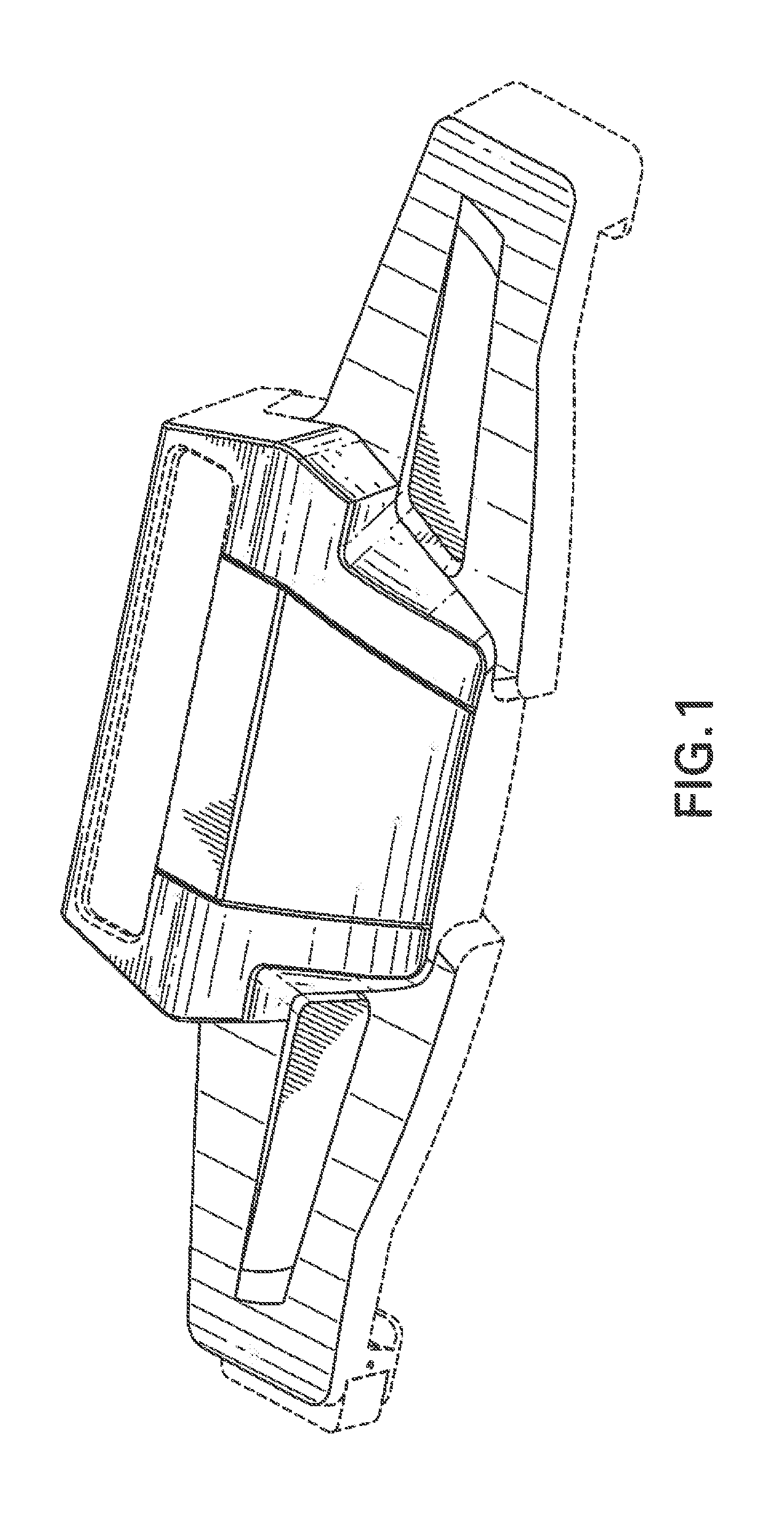
[0007] FIG. 1 is a perspective view of an exemplary augmented-reality device into which can be fitted a commercially-available 3D camera (not shown), and having incorporated therein at least one processor that performs inventive methodology.
[0008] FIG. 2 is a flow chart of method steps in an inventive embodiment of wound measurement technology using computerized records-keeping.
[0009] FIG. 3 is a flow chart of method steps in an inventive embodiment of wound scan and measurement.
[0010] FIG. 4 is a flow chart of method steps in an inventive embodiment of wound detection.
[0011] FIG. 5 is a flow chart or method steps in an inventive embodiment of wound measurements.
DETAILED DESCRIPTION OF THE INVENTION
[0012] An imaging device according to the invention is useable to acquire 3D images that can be subjected to computer processing steps such as in virtual reality technology, authentic reality technology, mixed reality technology, augmented reality technology, etc.
[0013] A significant advantage of the inventive technology is its usefulness in connection with a patient who suffers from a wound, to compute a Wound Volume Measurement, advantageously without any ruler, grid, marker (or such physical object) needing to have been placed on, or near, the patient (particularly, onto the patient wound or onto skin near the patient wound). For patient-related usages, the invention mainly contemplates a human patient, but also can be used in connection with a veterinary patient.
[0014] The inventive technology further is useable in connection with imaging a range of real-world objects and real-world living beings without any physical object needing to have been placed on, or near, the real-world object or living being. Post-imaging steps vary depending on what was imaged and on the application, such as a gaming application, a limb reconstruction application, etc.
[0015] We sometimes refer herein to "touchless", by which we mean that the patient's wound and the wound's environ (or, in other embodiments, the real-world object or real-world living being) is untouched by any ruler, grid, marker, 3D camera, frame enclosure holding a 3D camera, or the like. For example, the inventive technology is useable to image a zoo animal from a safe distance, and the resulting imaged zoo animal is then useable, for example, in a game.
[0016] In one embodiment, an inventive augmented reality method comprises steps of: operating an imaging device to acquire a 3D image; using the acquired 3D image, performing a detection algorithm that comprises capping or an interpolation method on a 2-dimensional grid in order to reconstruct a surface; and performing at least one augmented reality processing step, virtual reality processing step, authentic reality processing step, or mixed reality processing step.
[0017] In the step of operating an imaging device to acquire a 3D image, examples of what is being imaged are, e.g., a real-world wound, a real-world object, a real-world living being.
[0018] In the step of operating an imaging device to acquire a 3D image, a preferred example of an imaging device is a 3D camera. Examples of a 3D camera for use in practicing the invention are, e.g., Real Sense 3D camera (manufactured by Intel); Orbbec Astra 3-D camera; ZED stereo 3-D camera by Stereolabs.
[0019] The invention may further be appreciated with reference to the following examples, without the invention being limited to these examples.
EXAMPLE 1
[0020] An imaging device according to this inventive Example is useable to acquire 3D images that can be subjected to computer processing steps. For example, an imaging device that we call "Presero" was constructed according to this example.
Example 1.1
[0021] An imaging device was constructed as follows, according to a novel algorithm that consists of two main parts: wound detection and wound measurement.
[0022] The algorithm applies to a 3D model of a human body part containing a wound. The 3D model is obtained from a scan performed by an inventive application. The algorithm is not applied directly to the 3D model. Instead, the generated 3D model is rendered with camera parameters providing a good view of the wound (typically perpendicular to the wound or to the body part where the wound is), from which the algorithm acquires the Z-buffer (depth map) Z. calculated by the rendering process and the corresponding 4-by-4 projection matrix P as an input. The rendering process is based on OpenGL API (The Industry Standard for High Performance Graphics), and hence we use here the OpenGL terminology.
[0023] In addition, the algorithm gets a user defined outer-wound contour C as a hint for the wound location.
[0024] The algorithm does NOT use any color information.
Wound Detection
[0025] The following steps are performed.
[0026] 1. Convert the Z-buffer Z to the depth image D. The conversion is given by:
D ( i , j ) = P ( 3 , 4 ) 2 Z ( i , j ) - 1 + P ( 3 , 3 ) , ( i , j ) .di-elect cons. R , ##EQU00001##
where R={1, . . . , m}.times.{1, . . . , n}, m is a number of rows and n is a number of columns in Z and D.
[0027] 2. Define a region of interest U for wound detection. We include in U all (i,j) R laying inside C, except border pixels (i=1 or i=m or
j=1 or j=n) and except pixels which depth is too close to the far parameter of P, i.e.,
D(i,j)>(1-.alpha.)P(3,4)/(P(3,3)+1),
where .alpha. is a small positive constant.
[0028] 3. Wound Capping. We reconstruct skin surface S over the wound in order to enhance wound appearance by subtracting S from D.
(a) Calculate the First Approximation.
[0029] Since wound boundary is unknown yet, we start from the region U. Namely, we solve the following discrete Laplace equation with respect to S
4S(i,j)=S(i-1,j)-S(i+1,j)-S(i,j-1)-S(i,j+1)=0
if (i,j) U, and
S(i,j)=D(i,j)
if (i,j) R\U.
(b) Iteratively Raise the Capping if Required.
[0030] There is a possibility that the surface S is situated below the wound boundary. In this case S has to be raised. Let h be a maximum value of S-D. If, for some small tolerance threshold .delta.>0h>.delta., then we find all pixels (i,j) U such that
S(i,j)-D(i,j).gtoreq.h-.delta..
Assuming that these pixels are mostly (up to the threshold .delta.) outside the wound we redefine the is region U by excluding these pixels from it. We return to the steps (3a) and (3b) with the updated region U. We proceed in this way until h.ltoreq..delta. or maximal allowed number of iterations is reached.
[0031] 4. Detect a wound. To detect a wound we apply Chan-Vese algorithm (see T. Chan and L. Vese, Active contours without edges. IEEE Trans. Image Processing, 10 (2):266-277, February 2001) to the difference F=D-S. The Chan-Vese approach is to find among all 2-valued functions of the form
.phi. ( i , j ) = { c 1 if ( i , j ) .di-elect cons. W , c 2 if ( i , j ) .di-elect cons. R \ W , ##EQU00002##
the one that minimizes the following energy functional,
.mu.Length(.differential.W)+.nu.Area(W)+.lamda..sub.1.SIGMA..sub.(i,j) W(F(i,j)-c.sub.1).sup.2+.lamda..sub.2.SIGMA..sub.(i,j) R\W(F(i,j)-c.sub.2).sup.2,
where .differential.W denotes the boundary of W, .mu.>0, .nu..gtoreq.0, .lamda..sub.1>0, .lamda..sub.2>0 are fixed parameters. Let W, c.sub.1 and c.sub.2 minimize the energy functional. We interpret W as a set of pixels belonging to the wound.
[0032] 5. Correct wound boundary. The wound boundary .differential.W obtained in (4) is not accurate enough. It is located somewhere on the wound walls, but not necessarily on the top of them. We move it to the top as described below.
[0033] Starting from each pixel (i,j) .differential.W we go in the direction orthogonal to .differential.W and select a pixel (p(i,j), q(i,j)) located on the top of the wound wall by searching for the maximum value of the directional second derivative of the depth image D. Our intention is to move pixels (i,j) to pixels
(p(i,j), q(i,j)), but this operation can break continuity of the wound boundary. Denote by dist(i,j,A) the euclidean distance from the pixel (i,j) to the set of pixels A. Let
.DELTA.(i,j)=dist(i,j,W)-dist(i,j,R\W).
For any t>0, the set W.sub.t={(i,j) R:.DELTA.(i,j)<t} is an uniform expansion of W with size controlled by t, W.sub.0=W. In order to make this kind of expansion more flexible we replace t with a function T(i,j) which on the one hand has to be close to a constant, and on the other hand has to get values close to dist(p(i,j), q(i,j), W) at the pixels (p(i,j), q(i,j)). We find T as the solution of the following optimization problem
.SIGMA..sub.i=2.sup.m.SIGMA..sub.j=1.sup.n[T(i,j)-T(i-1,j)].sup.2+.SIGMA- ..sub.i=1.sup.m.SIGMA..sub.j=2.sup.n[T(i,j)-T(i,j-1)].sup.2+.rho..SIGMA..s- ub.(i,j) .differential.W[T(p(i,j),q(i,j))-dist(p(i,j),q(i,j),W)].sup.2.fwd- arw.min,
where .rho.>0 is a constant parameter. Finally, we declare
W*={(i,j) R:.DELTA.(i,j).ltoreq.T(i,j)}
[0034] as a set of the wound pixels,
Wound Measurements
[0035] Formulas for calculating wound volume, maximal depth, area, perimeter, length and width are set forth below. Note that the last 4 measurements are calculated for wound projection onto a plane parallel to the camera image plane.
[0036] In order to calculate wound volume we perform capping again as described in (3a) using W* instead of U. Let S* be the result. We clamp it as follows
S*=min(S*,D).
Then
[0037] WoundVolume = 4 3 mnP ( 1 , 1 ) P ( 2 , 2 ) .SIGMA. ( i , j ) .di-elect cons. W . ( D ( i , j ) 3 - S * ( i , j ) 3 ) , WoundMaximalDepth = max { D ( i , j ) - S * ( i , j ) , ( i , j ) .di-elect cons. W * } . ##EQU00003##
Tracing the wound boundary .differential.W* we write down all pixels belonging to .differential.W* as a sequence (i.sub.1j.sub.1), (i.sub.2,j.sub.2), . . . , (i.sub.N,j.sub.N). Let Q be the inverse matrix of P and let for each k=1, . . . , N,
X k = Q ( 1 , 1 ) x k + Q ( 1 , 4 ) Q ( 4 , 3 ) z k + Q ( 4 , 4 ) , Y k = Q ( 2 , 2 ) y k + Q ( 2 , 4 ) Q ( 4 , 3 ) z k + Q ( 4 , 4 ) , where ##EQU00004## x k = ( 2 / n ) ( j k - 0.5 ) - 1 , y k = - ( 2 / m ) ( i k - 0.5 ) + 1 , z k = - P ( 3 , 3 ) + P ( 3 , 4 ) D ( i k , j k ) . ##EQU00004.2##
Put, in addition, X.sub.0=X.sub.N,Y.sub.0=Y.sub.N and Y.sub.N+1=Y.sub.1.
Then
[0038] WoundArea=|.SIGMA..sub.k=1.sup.NX.sub.k(Y.sub.k+1-Y.sub.k-1)|,
WoundPerimeter=.SIGMA..sub.k=1.sup.N {square root over ((X.sub.k-X.sub.k-1).sup.2+(Y.sub.k-Y.sub.k-1).sup.2.)}
Assuming that a human body orientation is defined by an angle .theta., wound length and width are given by
WoundLength=max {X.sub.k cos .theta.+Y.sub.k sin .theta.,1.ltoreq.k.ltoreq.N}-min {X.sub.k cos .theta.+Y.sub.k sin .theta.,1.ltoreq.k.ltoreq.N},
WoundWidth=max {-X.sub.k sin .theta.+Y.sub.k cos .theta.,1.ltoreq.k.ltoreq.N}-min {-X.sub.k sin .theta.+Y.sub.k cos .theta.,1.ltoreq.k.ltoreq.N}.
REFERENCES
[0039] 1. T. Chan and L. Vese, Active contours without edges. IEEE Trans. Image Processing, 10 (2):256-277, February 2001.
EXAMPLE 1A
[0040] Optimal values for algorithm parameters in Example 1 are determined by testing the system on phantom wounds and other forms made from plasticine. For .alpha. (a small positive constant), 0.01 was chosen.
EXAMPLE 1B
[0041] In this example, when an inventive device used according to an above example, an image was ready to view within 10 seconds of camera operation.
EXAMPLE 1C
[0042] In this example, when an inventive device was used according to an above example, after a scan was completed, a 3D image was displayed to a user, and the displayed 3D image was subject to being manipulated by a finger of the user.
EXAMPLE 1D
[0043] In this example according to Example 1C, a user manipulated a wound image on screen with the user's finger, including, the user looked behind and under a wound image on screen.
EXAMPLE 1E
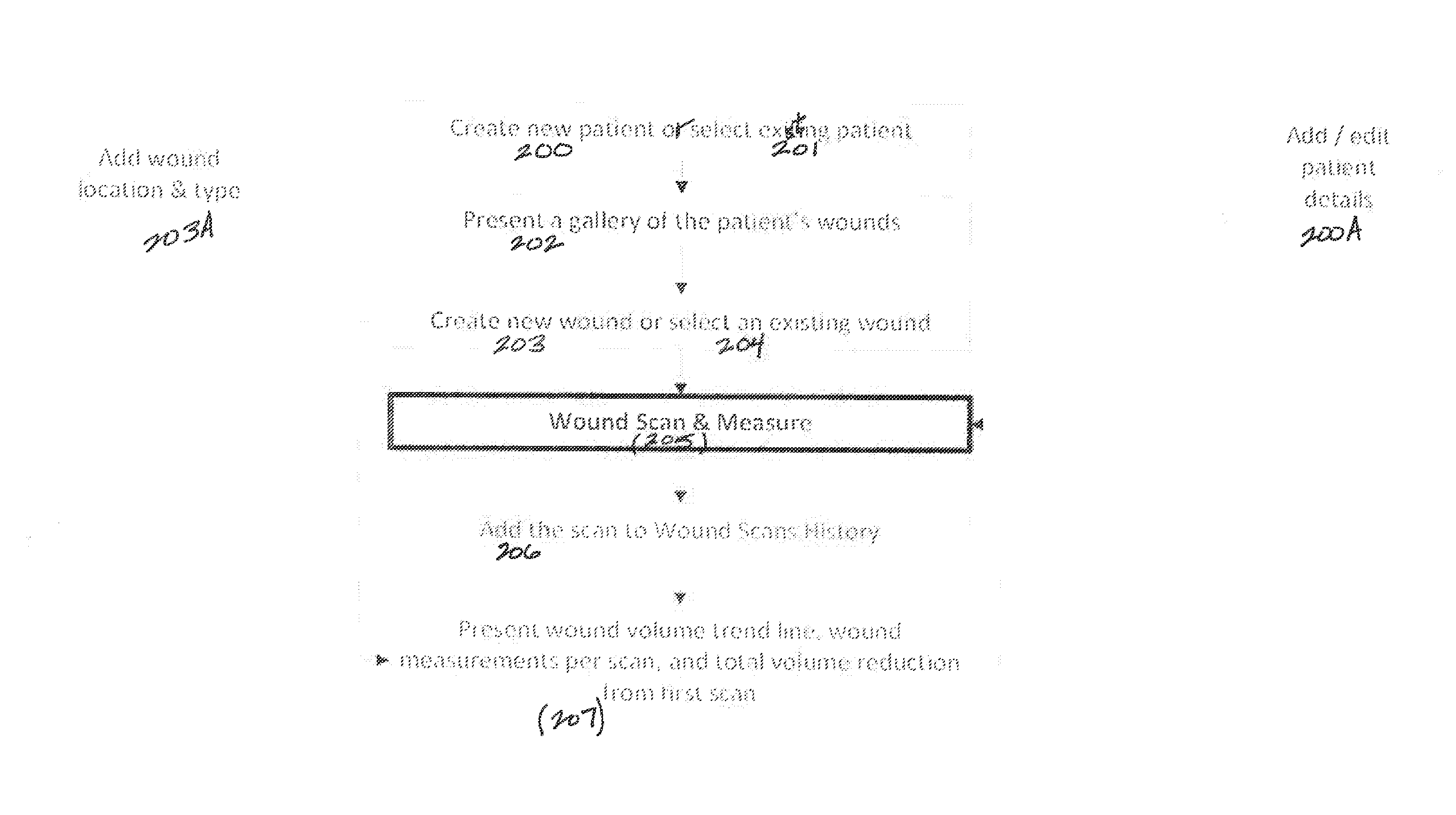
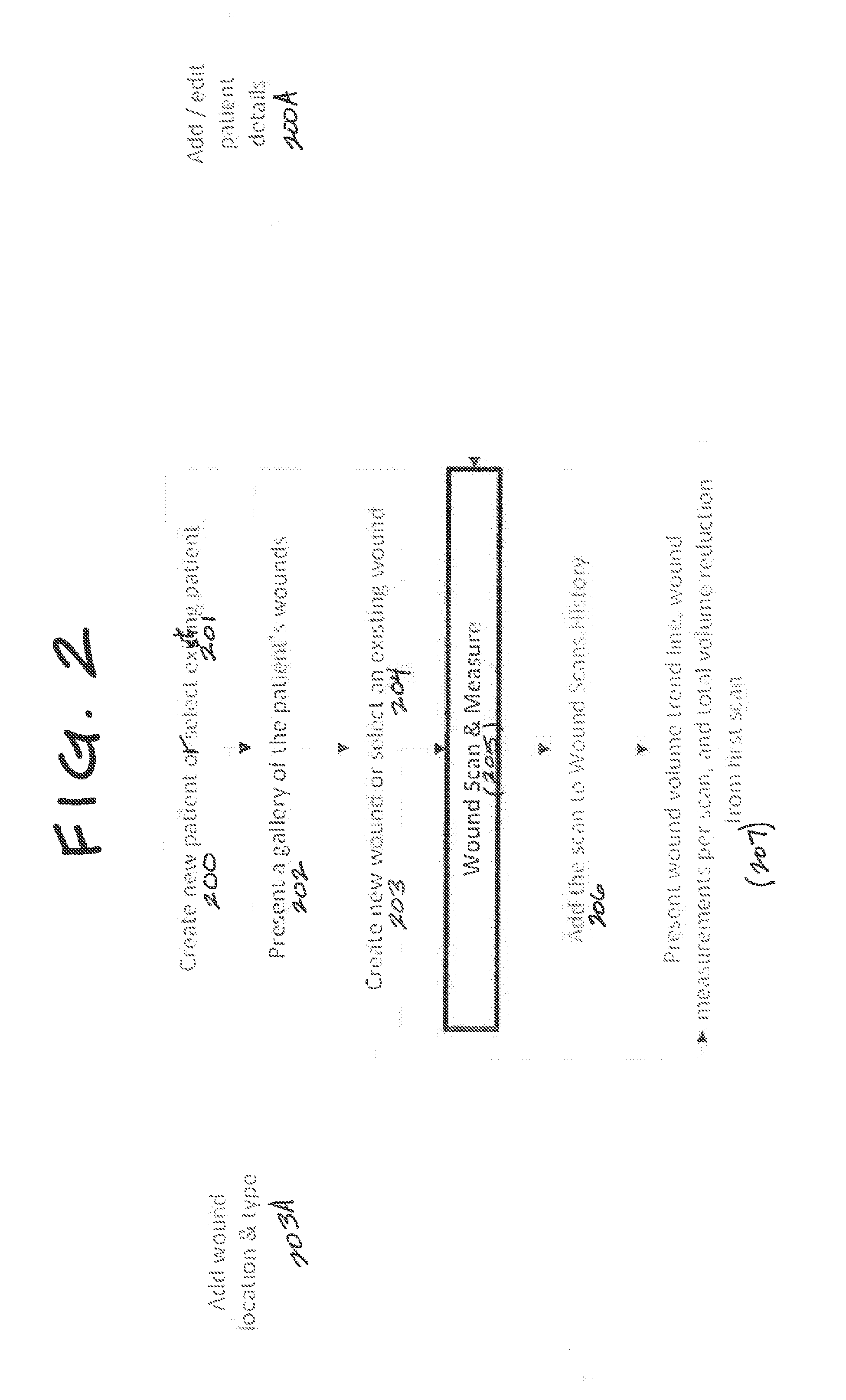
[0044] Referring to FIG. 2, in this Example, method steps are performed of: creating 200 a New Patient record or selecting 201 an Existing Patient record; presenting 202 a gallery of the patient's wounds; creating 203 a new Wound record or selecting 204 an existing Wound record; performing Wound Scan & Measurement 205; adding 206 the scan to Wound Scans History; presenting 207 Wound Volume trend line, Wound Measurement Per Scan, and Total Volume Reduction from first scan.
EXAMPLE 1F
[0045] Referring to FIG. 2, optionally steps of adding 203A wound location and type (to the Wound Record, and/or adding/editing 200A patient details to the Patient Record, are performed.
EXAMPLE 1F
Wound Scan & Measurement
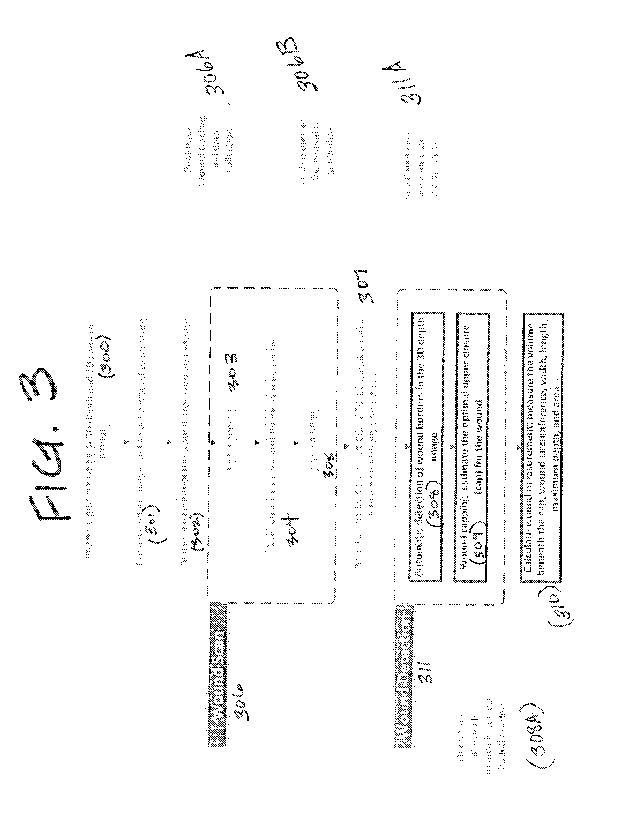
[0046] Referring to FIG. 3, in this Example, method steps are performed of: Image Acquisition 300 using a 3D depth and 2D camera module; previewing 301 video images and selecting a wound to measure; aiming 302 at the center of the wound, from a proper distance; starting 303 scanning; manipulating 304 the camera around the wound center; stopping 305 scanning; a step 307, performed by an operator, of marking a wound contour as a first estimation and defining wound-body orientation; automatic detection 308 of wound borders in the 3D depth image; wound capping 309 (comprising estimating the optimal upper closure (i.e., cap) for the wound); calculating 310 wound measurement (comprising measuring the volume beneath the cap, wound circumference, width, length, maximum depth, and area).
[0047] Steps 303, 304, 305 are referred to as Wound Scan 306 steps.
[0048] Steps 308, 309, 310 are referred to as Wound Detection 311 steps.
EXAMPLE 1G
[0049] Referring to FIG. 3, optionally the operator is allowed to manually correct 308A bound borders.
EXAMPLE 1H
[0050] Referring to FIG. 3, optionally real-time wound tracking and data collection are output in an outputting step 306.
EXAMPLE 1I
[0051] Referring to FIG. 3, optionally a 3D model of the wound is generated in a generating step 306B.
EXAMPLE 1J
[0052] Referring to FIG. 3, optionally the 3D model of Example 2.8B is presented to the operator in a displaying step 311A.
EXAMPLE 1K
Wound Detection
[0053] Referring to FIG. 4, in this Example, steps are performed of: a step 401 of rendering the 3D wound model from a perpendicular camera and generating Z-buffer (using OpenGL); converting 402 the Z-buffer to depth image; defining 403 a region of interest U for wound detection; wound capping 404 (comprising reconstructing skin surface over the wound); rough wound boundaries detection 405; and refined wound boundaries detection 406.
EXAMPLE 1L
Wound Measurements
[0054] Referring to FIG. 5, in this Example, steps are performed of: measuring 501 distances from capping to wound floor; calculating 502 volume by summing distances in all pixels inside the wound; calculating 503 maximum depth (max distances); summating 504 perimeter length equaling total length of detected wound boundaries; calculating 505 wound area from detected wound boundaries; calculating 506 max wound length & width by aligning the wound contour to body angle; and calculating 507 presented area as Max length.times.Max width.
EXAMPLE 2
[0055] In this example, an imaging device of Examples 1-1A is used to image something other than a wound.
EXAMPLE 3
[0056] In this example, when an imaging device was used according to any of Examples 1-2, an image was ready to view within 10 seconds of camera operation.
EXAMPLE 4
[0057] In this example, when an imaging device was used according to any of Examples 1-3, after a scan was completed, a 3D image was displayed to a user, and the displayed 3D image was subject to being manipulated by a finger of the user.
EXAMPLE 4A
[0058] In this example according to Example 4, a user manipulated a wound image on screen with the user's finger, including to look behind and under a wound image on screen.
EXAMPLE 5
[0059] An imaging device for imaging an Object which may be other than a wound is constructed. A 3D model of the Object is obtained from a scan performed by the imaging application. The algorithm is not applied directly to the 3D model. Instead, the generated 3D model is rendered with camera parameters providing a good view of the Object (typically perpendicular to the Object or to the region where the Object is), from which the algorithm acquires the Z-buffer (depth map) Z, calculated by the rendering process and the corresponding 4-by-4 projection matrix P as an input. The rendering process is based on OpenGL API.
[0060] In addition, the algorithm gets a user defined outer-Object contour C as a hint for the Object location.
EXAMPLE 5.1
Object Detection
[0061] This Object-Detection part of the algorithm is represented by the following steps.
1. Convert the Z-buffer Z to the Depth Image D.
[0062] The conversion is given by
D ( i , j ) = P ( 3 , 4 ) 2 Z ( i , j ) - 1 + P ( 3 , 3 ) , ( i , j ) .di-elect cons. R , ##EQU00005##
Where R=[1, . . . , m].times.[1, . . . , n], m is a number of rows and n is a number of columns in Z And D.
2. Define a Region of Interest U for Object Detection.
[0063] We include in U all (i,j) R laying inside C, except border pixels (i=1 or i=m or j=1 or j=n) and except pixels which depth is too close to the far parameter of P, i.e.,
D(i,j)>(1-.alpha.)P(3,4)/(P(3,3)+1),
Where .alpha. is a small positive constant.
3. Object Capping.
[0064] We reconstruct skin surface S over the Object in order to enhance Object appearance by subtracting S from D.
(a) Calculate the First Approximation.
[0065] Because Object boundary is unknown yet, we start from the region U. Namely, we solve the following discrete Laplace equation with respect to S
4S(i,j)-S(i-1,j)-S(i+1,j)-S(i,j-1)-S(i,j+1)=0
if (i,j) U, and
S(i,j)=D(i,j)
if (i,j) R\U.
(b) Iteratively Raise the Capping if Required.
[0066] There is a possibility that the surface S is situated below the Object boundary. In this case S has to be raised. Let h be a maximum value of S-D. If, for some small tolerance threshold .delta.>0h>.delta., then we find all pixels (i,j) U such that
S(i,j)-D(i,j).gtoreq.h-.delta..
Assuming that these pixels are mostly (up to the threshold .delta.) outside the Object we redefine the region U by excluding these pixels from it. We return to the steps (3a) and (3b) with the updated region U. We proceed in this way till h.ltoreq..delta. or maximal allowed number of iterations is reached.
4. Detect an Object.
[0067] To detect an Object we apply Chan-Vese algorithm [1] to the difference F=D-S. The Chan-Vere approach is to find among all 2-valued functions of the form
.phi. ( i , j ) = { c 1 if ( i , j ) .di-elect cons. W , c 2 if ( i , j ) .di-elect cons. R \ W , ##EQU00006##
the one that minimizes the following energy functional,
.mu.Length(.differential.W)+.nu.Area(W)+.lamda..sub.1.SIGMA..sub.(i,j) W(F(i,j)-c.sub.1).sup.2+.lamda..sub.2.SIGMA..sub.(i,j) R\W(F(i,j)-c.sub.2).sup.2,
Where .differential.W denotes the boundary of W, .mu.>0, .nu..gtoreq.0, .lamda..sub.1>0, .lamda..sub.2>0 are fixed parameters.
[0068] Let W, c.sub.1 and c.sub.2 minimize the energy functional. We interpret W as a set of pixels belonging to the wound.
5. Correct Object Boundary.
[0069] The Object boundary .differential.W obtained in (4) is not accurate enough. It is located somewhere on the Object walls, but not necessarily on the top of them. We move it to the top as described below.
[0070] Starting from each pixel (i,j) .differential.W we go in the direction orthogonal to .differential.W and select a pixel (p(i,j), q(i,j)) located on the top of the wound wall by searching for the maximum value of the directional second derivative of the depth image D. Our intention is to move pixels (i,j) to pixels (p(i,j), q(i,j)), but this operation can break continuity of the Object boundary.
[0071] Denote by dist(i,j,A) the euclidean distance from the pixel (i,j) to the set of pixels A. Let
.DELTA.(i,j)=dist(i,j,W)-dist(i,j,R\W).
[0072] For any t>0, the set W.sub.t={(i,j) R:.DELTA.(i,j)<t} is an uniform expansion of W with size controlled by t, W.sub.0=W. In order to make this kind of expansion more flexible we replace t with a function T(i,j) which on the one hand has to be close to a constant, and on the other hand has to get values close to dist(p(i,j), q(i,j),W) at the pixels (p(i,j), q(i,j)).
[0073] We find T as the solution of the following optimization problem
.SIGMA..sub.i=2.sup.m.SIGMA..sub.j=1.sup.n[T(i,j)-T(i-1,j)].sup.2+.SIGMA- ..sub.i=1.sup.m.SIGMA..sub.j=2.sup.n[T(i,j)-T(i,j-1)].sup.2+.rho..SIGMA..s- ub.(i,j) .differential.W[T(p(i,j),q((i,j))=dist(p(i,j),q(i,j),W)].sup.2.fw- darw.min,
where .rho.>0 is a constant parameter. Finally, we declare
W*={(i,j) R:.DELTA.(i,j).ltoreq.T(i,j)}
as a set of the Object pixels.
Example 5.2
Object Measurements
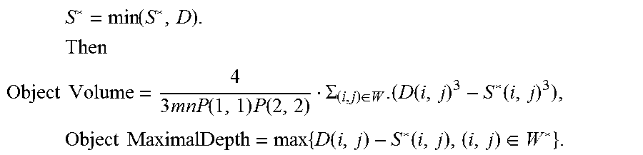
[0074] In this part we present formulas for calculating Object volume, maximal depth, area, perimeter, length and width. The last 4 measurements are calculated for Object projection onto a plane parallel to the camera image plane.
[0075] In order to calculate Object volume we perform capping again as described in *3a) using W* instead of U. Let S* be the result. We clamp it as follows
X k = Q ( 1 , 1 ) x k + Q ( 1 , 4 ) Q ( 4 , 3 ) z k + Q ( 4 , 4 ) , ##EQU00007##
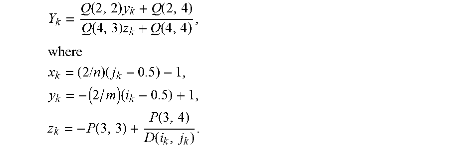
[0076] Tracing the Object boundary .differential.W* we write down all pixels belonging to .differential.W* as a sequence (i.sub.1j.sub.1), (i.sub.2,j.sub.2), . . . , (i.sub.N,j.sub.N). Let Q be the inverse matrix of P and let for each k=1, . . . , N,
S * = min ( S * , D ) . Then ##EQU00008## Object Volume = 4 3 mnP ( 1 , 1 ) P ( 2 , 2 ) .SIGMA. ( i , j ) .di-elect cons. W . ( D ( i , j ) 3 - S * ( i , j ) 3 ) , Object MaximalDepth = max { D ( i , j ) - S * ( i , j ) , ( i , j ) .di-elect cons. W * } . ##EQU00008.2##
Y k = Q ( 2 , 2 ) y k + Q ( 2 , 4 ) Q ( 4 , 3 ) z k + Q ( 4 , 4 ) , where ##EQU00009## x k = ( 2 / n ) ( j k - 0.5 ) - 1 , y k = - ( 2 / m ) ( i k - 0.5 ) + 1 , z k = - P ( 3 , 3 ) + P ( 3 , 4 ) D ( i k , j k ) . ##EQU00009.2##
Put, in addition, X.sub.0=X.sub.N, Y.sub.0=Y.sub.N and Y.sub.N+1=Y.sub.1.
Then
[0077] ObjectArea=|.SIGMA..sub.k=1.sup.NX.sub.k(Y.sub.k+1-Y.sub.k-1)|,
ObjectPerimeter=.SIGMA..sub.k=1.sup.N {square root over ((X.sub.k-X.sub.k-1).sup.2+(Y.sub.k-Y.sub.k-1).sup.2)}.
Assuming that a Locality orientation is defined by an angle .theta., Object length and width are given by
ObjectLength=max{X.sub.k cos .theta.+Y.sub.k sin .theta.,1.ltoreq.k.ltoreq.N}-min {X.sub.k cos .theta.+Y.sub.k sin .theta.,1.ltoreq.k.ltoreq.N},
ObjectWidth=max[-X.sub.k sin .theta.+Y.sub.k cos .theta.,1.ltoreq.k.ltoreq.N]-min[-X.sub.k sin .theta.+Y.sub.k cos .theta.,1.ltoreq.k.ltoreq.N].
Example 5.3
[0078] An example of an Object in Example 5.1 (Object Detection) above is an intact body part that is being 3D-imaged and the 3D image is processed in at least one prosthesis-modeling or prosthesis-construction steps.
[0079] The above described embodiments are set forth by way of example and are not limiting. It will be readily apparent that obvious modification, derivations and variations can be made to the embodiments. The claims appended hereto should be read in their full scope including any such modifications, derivations and variations.
* * * * *
D00000
D00001
D00002
D00003
D00004
D00005

XML
uspto.report is an independent third-party trademark research tool that is not affiliated, endorsed, or sponsored by the United States Patent and Trademark Office (USPTO) or any other governmental organization. The information provided by uspto.report is based on publicly available data at the time of writing and is intended for informational purposes only.
While we strive to provide accurate and up-to-date information, we do not guarantee the accuracy, completeness, reliability, or suitability of the information displayed on this site. The use of this site is at your own risk. Any reliance you place on such information is therefore strictly at your own risk.
All official trademark data, including owner information, should be verified by visiting the official USPTO website at www.uspto.gov. This site is not intended to replace professional legal advice and should not be used as a substitute for consulting with a legal professional who is knowledgeable about trademark law.