Ice Making Device
SAITO; Shunji ; et al.
U.S. patent application number 16/116941 was filed with the patent office on 2019-02-28 for ice making device. This patent application is currently assigned to NIDEC SANKYO CORPORATION. The applicant listed for this patent is NIDEC SANKYO CORPORATION. Invention is credited to Yuji MARUYAMA, Shunji SAITO, Manabu SAKAMOTO, Hideo SHIMODAIRA.
| Application Number | 20190063812 16/116941 |
| Document ID | / |
| Family ID | 65321546 |
| Filed Date | 2019-02-28 |


View All Diagrams
| United States Patent Application | 20190063812 |
| Kind Code | A1 |
| SAITO; Shunji ; et al. | February 28, 2019 |
ICE MAKING DEVICE
Abstract
An ice making device is provided. In the ice making device, a drive unit includes an ice sensing shaft driven to rotate by a cam surface of a cam gear, a biasing member that biases the ice sensing shaft toward the cam surface, and a second case member. The second case member includes a stopper that comes in contact with the ice sensing shaft from one side of the ice sensing shaft in an axis and limits the ice sensing shaft in the axis direction when the ice sensing shaft is assembled and the biasing member is elastically deformed. When the ice sensing shaft positioned by the stopper is rotated around the axis, a spring engaging part passes through a notch of a side wall and compresses the biasing member.
| Inventors: | SAITO; Shunji; (NAGANO, JP) ; SAKAMOTO; Manabu; (NAGANO, JP) ; MARUYAMA; Yuji; (NAGANO, JP) ; SHIMODAIRA; Hideo; (NAGANO, JP) | ||||||||||
| Applicant: |
|
||||||||||
|---|---|---|---|---|---|---|---|---|---|---|---|
| Assignee: | NIDEC SANKYO CORPORATION Nagano JP |
||||||||||
| Family ID: | 65321546 | ||||||||||
| Appl. No.: | 16/116941 | ||||||||||
| Filed: | August 30, 2018 |
| Current U.S. Class: | 1/1 |
| Current CPC Class: | F25C 2700/02 20130101; F25C 5/187 20130101; F25C 1/10 20130101; F25C 5/06 20130101; F25C 2305/022 20130101 |
| International Class: | F25C 1/10 20060101 F25C001/10; F25C 5/06 20060101 F25C005/06 |
Foreign Application Data
| Date | Code | Application Number |
|---|---|---|
| Aug 31, 2017 | JP | 2017-166786 |
Claims
1. An ice making device comprising: an ice making tray in which recessed parts for water storage are disposed upward; and a drive unit that drives to rotate the ice making tray around a first axis that extends in a direction crossing a vertical direction, wherein the drive unit comprises a cam gear connected to the ice making tray, an ice sensing shaft that is connected to an ice detection lever and is driven to rotate by a cam surface of the cam gear, a biasing member that biases the ice sensing shaft toward the cam surface, and a supporting member that supports the cam gear, the ice sensing shaft, and the biasing member, and wherein the supporting member comprises a stopper that comes in contact with the ice sensing shaft from one side in a second axis direction, which is a direction of a second axis an axis of the ice sensing shaft, and the stopper limits a position of the ice sensing shaft in the second axis direction when the biasing member is elastically deformed by assembling the ice sensing shaft.
2. The ice making device according to claim 1, wherein the biasing member is a compression coil spring whose axis direction goes along a direction crossing the second axis, and wherein a spring engaging part protrudes from an outer circumferential surface of the ice sensing shaft, the spring engaging part is in contact with one end of the compression coil spring and compresses the compression coil spring when the ice sensing shaft is rotated around the second axis while the position of the ice sensing shaft is limited by the stopper.
3. The ice making device according to claim 2, wherein the supporting member comprises a partition wall on which a notch is provided at a position that faces the one end of the compression coil spring, and wherein, when the ice sensing shaft is rotated around the second axis at the position limited by the stopper, the spring engaging part passes through the notch and comes in contact with the one end of the compression coil spring.
4. The ice making device according to claim 3, wherein, when the ice sensing shaft has been assembled, the spring engaging part is at a position biased to one side of the notch in the second axis direction.
5. The ice making device according to claim 4, wherein the spring engaging part is in contact with the one end of the compression coil spring at a position biased to one side from a center of the partition wall in the second axis direction.
6. The ice making device according to claim 4, wherein, an inclined part is formed on at least one of a side end disposed on a side opposite to the compression coil spring in the spring engaging part and a partition wall side end that faces the side end in the partition wall, the inclined part moves the ice sensing shaft to one side in the second axis direction by a biasing force of the compression coil spring when the side end comes in contact with the partition wall side end.
7. The ice making device according to claim 6, wherein the inclined part is formed as a surface on one of the side end and the partition wall side end and is formed as a convex part on the other of the side end (31t) and the partition wall side end.
8. The ice making device according to claim 6, wherein the inclined part is formed on both the side end and the partition wall side end.
9. The ice making device according to claim 8, wherein the inclined part is formed as a surface on both the side end and the partition wall side end.
10. The ice making device according to claim 1, wherein the stopper is a step part that is formed on a base of a seat part at which a screw is stopped in the supporting member.
11. The ice making device according to claim 1, wherein the stopper is a plate-like convex part that protrudes from the supporting member.
Description
CROSS-REFERENCE TO RELATED APPLICATION
[0001] This application claims the priority benefit of Japan application serial no. 2017-166786, filed on Aug. 31, 2017. The entirety of the above-mentioned patent application is hereby incorporated by reference herein and made a part of this specification.
BACKGROUND
Technical Field
[0002] The disclosure relates to an ice making device configured to drive an ice sensing shaft by a cam surface of a cam gear connected to an ice making tray.
Related Art
[0003] An ice making device mounted on a refrigerator includes an ice making tray in which recessed parts for water storage are disposed upward and a drive unit that drives to rotate the ice making tray around an axis that extends in a direction crossing a vertical direction. The drive unit includes a cam gear connected to the ice making tray, an ice sensing shaft that is driven to rotate by a cam surface of the cam gear, and a compression coil spring that biases the ice sensing shaft toward the cam surface. An ice detection lever rotates with the ice sensing shaft in connection with the cam gear and performs an ice detection operation (refer to Japanese Laid-open Publication No. 2001-165539). In the ice making device described in Japanese Laid-open Publication No. 2001-165539, in a supporting member that supports the cam gear, the ice sensing shaft, and the like, a partition wall on which a notch is provided at a position that faces one end of the compression coil spring is formed. When the ice sensing shaft is assembled, a position of the ice sensing shaft in the axis direction is adjusted, a spring engaging part and the notch are aligned, and the ice sensing shaft is then rotated around the axis. As a result, the spring engaging part passes through the notch, comes in contact with one end of the compression coil spring and compresses the compression coil spring.
[0004] However, in the configuration described in Japanese Laid-open Publication No. 2001-165539, when the ice sensing shaft is assembled, since it is necessary to adjust a position of the ice sensing shaft in the axis direction and align the spring engaging part and the notch (compression coil spring), much time and effort is required. In addition, misalignment is likely to occur between the spring engaging part of the ice sensing shaft and the compression coil spring, and in an extreme case, the ice sensing shaft is assembled in a state in which the spring engaging part restricts the end of the compression coil spring from above.
SUMMARY
[0005] An ice making device according to the disclosure includes an ice making tray in which recessed parts for water storage are disposed upward; and a drive unit that drives to rotate the ice making tray around a first axis that extends in a direction crossing a vertical direction, wherein the drive unit includes a cam gear connected to the ice making tray, an ice sensing shaft that is connected to an ice detection lever and is driven to rotate by a cam surface of the cam gear, a biasing member that biases the ice sensing shaft toward the cam surface, and a supporting member that supports the cam gear, the ice sensing shaft, and the biasing member, and wherein the supporting member includes a stopper that comes in contact with the ice sensing shaft from one side in a second axis direction, which is a direction of a second axis, an axis of the ice sensing shaft, and the stopper limits a position of the ice sensing shaft in the second axis direction when the biasing member is elastically deformed by assembling the ice sensing shaft.
BRIEF DESCRIPTION OF THE DRAWINGS
[0006] FIG. 1 is a perspective view of an ice making device to which the disclosure is applied when viewed from the side on which a second side plate is disposed and viewed obliquely from above.
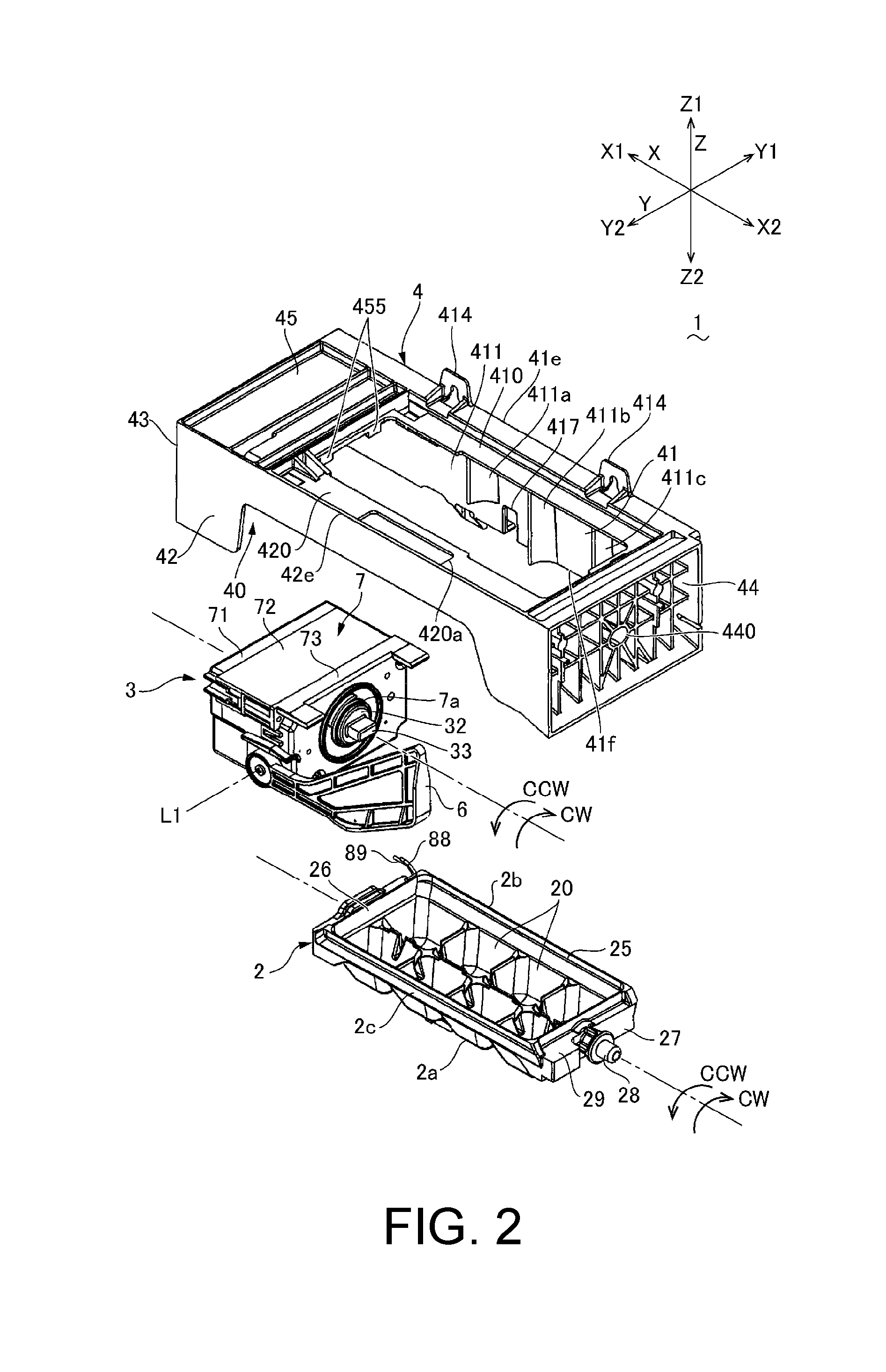
[0007] FIG. 2 is an exploded perspective view of the ice making device shown in FIG. 1 when viewed from the side on which the second side plate is disposed and viewed obliquely from above.
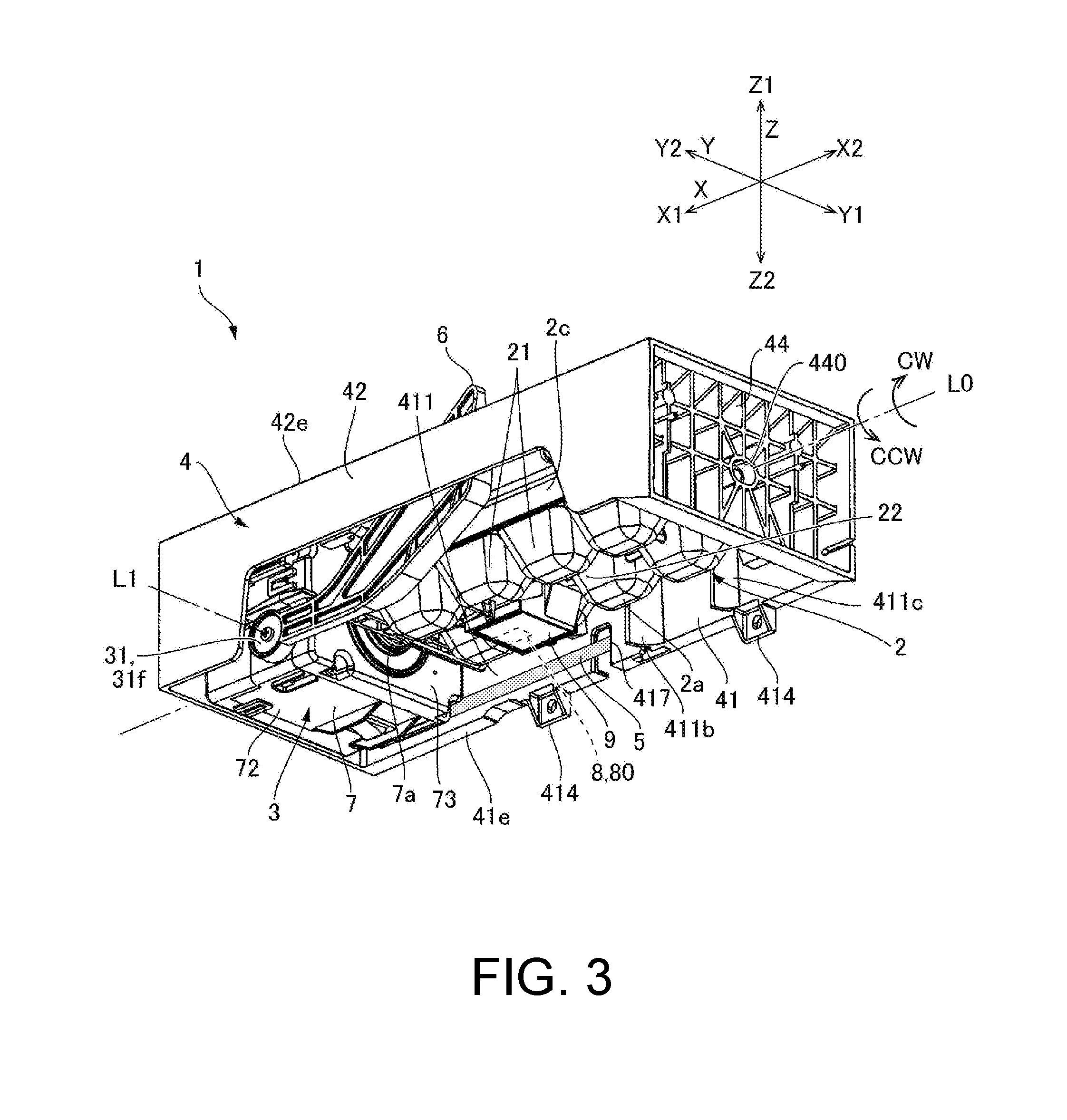
[0008] FIG. 3 is an exploded perspective view of the ice making device shown in FIG. 1 when viewed from the side on which the second side plate is disposed and viewed obliquely from below.
[0009] FIG. 4 is an exploded perspective view of an aspect in which a drive unit shown in FIG. 2 is disassembled when viewed from the side on which an ice making tray is disposed.
[0010] FIG. 5 is an exploded perspective view of an aspect in which a drive unit shown in FIG. 2 is disassembled when viewed from the side opposite to the ice making tray.
[0011] FIG. 6 is a perspective view of a drive mechanism shown in FIG. 4.
[0012] FIG. 7 is a perspective view of a state in which a cam gear is removed from the state shown in FIG. 6.
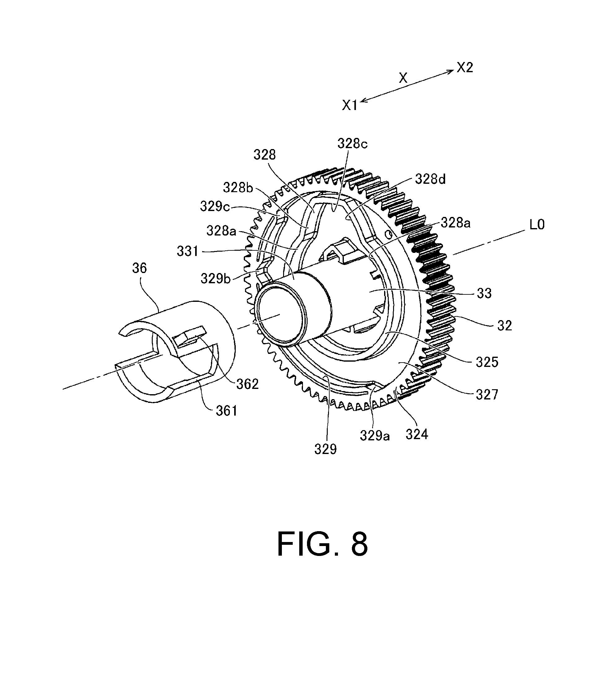
[0013] FIG. 8 is an exploded perspective view of a cam gear and the like shown in FIG. 5 when viewed from the side opposite to the ice making tray.
[0014] FIG. 9 is an explanatory diagram of an ice sensing shaft shown in FIG. 7.
[0015] FIGS. 10(a).about.10(c) show explanatory diagrams of a method of assembling the ice sensing shaft shown in FIG. 7.
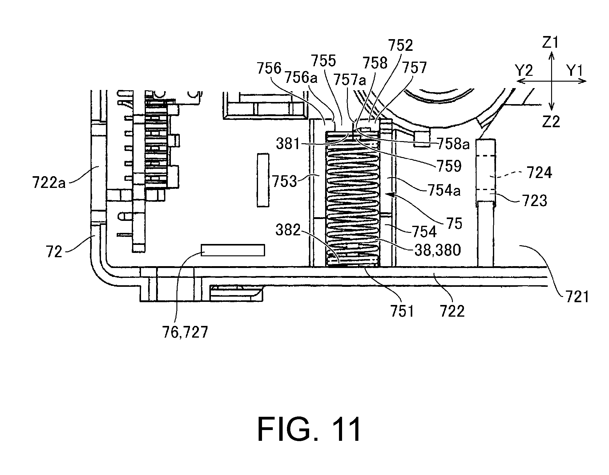
[0016] FIG. 11 is an explanatory diagram showing a modified example of a stopper used in an ice making device to which the disclosure is applied.
DESCRIPTION OF THE EMBODIMENTS
[0017] An objective of an embodiment in the disclosure is to provide an ice making device that can appropriately and easily assemble an ice sensing shaft to a biasing member used for a drive unit.
[0018] In the disclosure, when the ice sensing shaft is assembled and the biasing member is elastically deformed, a position of the ice sensing shaft in the second axis direction is limited by the stopper of the supporting member. Therefore, since it is not necessary to align positions of the ice sensing shaft and the biasing member while a position of the ice sensing shaft in the second axis direction is adjusted, the ice sensing shaft can be assembled easily and efficiently. In addition, when the ice sensing shaft is assembled, since misalignment is unlikely to occur, the ice sensing shaft can be appropriately assembled with the biasing member.
[0019] In an aspect of the disclosure, the biasing member is a compression coil spring whose axis direction goes along a direction crossing the second axis. A spring engaging part protrudes from an outer circumferential surface of the ice sensing shaft, the spring engaging part is in contact with one end of the compression coil spring and compresses the compression coil spring when the ice sensing shaft is rotated around the second axis while the position of the ice sensing shaft is limited by the stopper. According to this aspect, the compression coil spring can be compressed by a simple operation of rotating the ice sensing shaft around the second axis while a position in the second axis direction is limited by the stopper of the supporting member.
[0020] In an aspect of the disclosure, the supporting member includes a partition wall on which a notch is provided at a position that faces the one end of the compression coil spring, and when the ice sensing shaft is rotated around the second axis at the position limited by the stopper, the spring engaging part passes through the notch and comes in contact with the one end of the compression coil spring. According to this aspect, even if a configuration in which the compression coil spring is disposed inside the partition wall is used, the ice sensing shaft can be assembled into the biasing member appropriately and easily.
[0021] In an aspect of the disclosure, when the ice sensing shaft has been assembled, the spring engaging part is at a position biased to one side of the notch in the second axis direction. According to this aspect, a situation in which the spring engaging part escapes from the notch of the partition wall is unlikely to occur.
[0022] In an aspect of the disclosure, the spring engaging part is in contact with the one end of the compression coil spring at a position biased to one side from a center of the partition wall in the second axis direction. According to this aspect, even if the spring engaging part is at a position biased to one side of the notch in the second axis direction, since the spring engaging part is in contact with one end of the compression coil spring, the compression coil spring can appropriately bias the ice sensing shaft through the spring engaging part.
[0023] In an aspect of the disclosure, an inclined part is formed on at least one of a side end disposed on a side opposite to the compression coil spring in the spring engaging part and a partition wall side end that faces the side end in the partition wall, the inclined part that moves the ice sensing shaft to one side in the second axis direction by a biasing force of the compression coil spring when the side end comes in contact with the partition wall side end. In this case, an aspect in which the inclined part is formed as a surface on one of the side end and the partition wall side end and is formed as a convex part on the other of the side end and the partition wall side end can be used. According to this aspect, the ice sensing shaft can be automatically moved to one side in the second axis direction due to a biasing force of the compression coil spring.
[0024] In an aspect of the disclosure, the inclined part is formed on both the side end and the partition wall side end. For example, an aspect in which the inclined part is formed as a surface on both the side end and the partition wall side end can be used. According to this aspect, the ice sensing shaft can be moved to one side in the second axis direction automatically and more reliably due to a biasing force of the compression coil spring.
[0025] In an aspect of the disclosure, the stopper is a step part that is formed on a base of a seat part at which a screw is stopped in the supporting member. In an aspect of the disclosure, the stopper is a plate-like convex part that protrudes from the supporting member.
[0026] In the disclosure, when the ice sensing shaft is assembled and the biasing member is elastically deformed, a position of the ice sensing shaft in the second axis direction is limited by the stopper of the supporting member. Therefore, since it is not necessary to align positions of the ice sensing shaft and the biasing member while a position of the ice sensing shaft in the second axis direction is adjusted, the ice sensing shaft can be assembled easily and efficiently. In addition, when the ice sensing shaft is assembled, since misalignment is unlikely to occur, the ice sensing shaft can be appropriately assembled with the biasing member.
[0027] Embodiments of the disclosure will be described with reference to the drawings. In the following description, three directions that cross each other will be described as a first direction X (length direction), a second direction Y (width direction), and a third direction Z (vertical direction). In addition, in the description, X1 refers to one side in the first direction X, X2 refers to the other side in the first direction X, Y1 refers to one side in the second direction Y, Y2 refers to the other side in the second direction Y, Z1 refers to one side (upper side) in the third direction Z (vertical direction), and Z2 refers to the other side (lower side) in the third direction Z (vertical direction).
[0028] (Overall Configuration)
[0029] FIG. 1 is a perspective view of an ice making device 1 to which the disclosure is applied when viewed from the side on which a second side plate 42 is disposed and viewed obliquely from above. FIG. 2 is an exploded perspective view of the ice making device 1 shown in FIG. 1 when viewed from the side on which the second side plate 42 is disposed and viewed obliquely from above. FIG. 3 is an exploded perspective view of the ice making device 1 shown in FIG. 1 when viewed from the side on which the second side plate 42 is disposed and viewed obliquely from below.
[0030] The ice making device 1 shown in FIG. 1 to FIG. 3 includes an ice making tray 2 in which recessed parts for water storage 20 (cells) are dispose toward the one side Z1 (upper side) in the third direction Z, a drive unit 3 that is disposed on the one side X1 of the ice making tray 2 in the first direction X, and a frame 4 including a mounting unit 40 on which the drive unit 3 is mounted. The ice making device 1 is mounted on a refrigerator main body (not shown). In the refrigerator, water in a water supply tank (not shown) is filled into the recessed parts for water storage 20 of the ice making tray 2 through a water supply pipe (not shown) and ice making is performed. Then, when the ice making is completed, the drive unit 3 causes the ice making tray 2 to perform an inversion operation around an axis L0 (first axis) that extends in the first direction X and a twist operation that is in connection with the inversion operation as an ice removal operation, and thereby causes ice in the ice making tray 2 to fall into an ice storage container (not shown).
[0031] (Configuration of Ice Making Tray 2)
[0032] The ice making tray 2 is a member that is made of a resin material and molded to have a substantially rectangular planar shape, and is made of an elastically deformable material. In the ice making tray 2, a plurality of recessed parts for water storage 20 are arranged in the first direction X and the second direction Y. For example, in the ice making tray 2, inside a frame part 25 having a substantially rectangular shape, two recessed parts for water storage 20 arranged in the second direction Y as a set are disposed in four rows in the first direction X. In the frame part 25 of the ice making tray 2, a connecting part (not shown) connected to an output shaft 33 of the drive unit 3 on the axis L0 is formed on a wall part 26 that is disposed on the one side X1 in the first direction X, and a shaft part 28 that is rotatably supported on the frame 4 on the axis L0 is formed on a wall part 27 that is disposed on the other side X2 in the first direction X. On the wall part 27 of the ice making tray 2, a rotation regulating part 29 that comes in contact with the frame 4 when the ice making tray 2 rotates around the axis L0 is formed. The rotation regulating part 29 causes the ice making tray 2 to perform a twist operation by preventing rotation of the ice making tray 2.
[0033] In the ice making tray 2, on a bottom surface 2a in the third direction Z, a plurality of convex parts 21 reflecting the shape of the plurality of recessed parts for water storage 20 are arranged. On the bottom surface 2a of the ice making tray 2, a temperature sensor 8 configured to detect a temperature of the ice making tray 2 is disposed. The temperature sensor 8 is covered with a cover member 9 fixed to the bottom surface 2a of the ice making tray 2. Signal wirings 88 and 89 extend from the temperature sensor 8 into the drive unit 3. In the present embodiment, the temperature sensor 8 is a thermistor 80.
[0034] (Configuration of Frame 4)
[0035] The frame 4 includes a first side plate 41 that extends in the first direction X along a first side surface 2b on one side Y1 of the ice making tray 2 in the second direction Y and the second side plate 42 that extends in the first direction X along a second side surface 2c on the other side Y1 of the ice making tray 2 in the second direction Y. The first side plate 41 and the second side plate 42 face each other in parallel in the second direction Y. An ice detection lever 6 whose base end side is connected to the drive unit 3 is disposed between the second side plate 42 and the ice making tray 2.
[0036] From an upper end 41e (edge on the one side Z1 in the third direction Z) of the first side plate 41, a first upper plate part 410 projects toward the second side plate 42. The first upper plate part 410 is bent downward at an intermediate position toward one side Y1 in the second direction Y and then projects toward the second side plate 42. From the vicinity of an upper end 42e (edge on the one side Z1 in the third direction Z) of the second side plate 42, a second upper plate part 420 projects toward the first side plate 41. The ice making tray 2 faces upward in an open state (the one side Z1 in the third direction Z) between the first upper plate part 410 and the second upper plate part 420. An opening 420a is formed in the second upper plate part 420. The upper end of the ice detection lever 6 is disposed inside the opening 420a.
[0037] Ends of the first side plate 41 and the second side plate 42 on the one side X1 in the first direction X overlap the drive unit 3 when viewed in the second direction Y. The first side plate 41 and the second side plate 42 are connected by a plate-like first wall part 43 that is disposed at an end on the one side X1 in the first direction X and a second wall part 44 that is disposed at an end on the other side X2 in the first direction X. The first side plate 41 and the second side plate 42 are also connected by an upper plate part 45 that covers the drive unit 3 from the upper side on the other side Y2 in the second direction Y. Accordingly, in the present embodiment, in the frame 4, a space surrounded by the first side plate 41, the second side plate 42, the first wall part 43, and the upper plate part 45 forms the mounting unit 40 of the drive unit 3. A lower part (the other side Z2 in the third direction Z) of the mounting unit 40 is in an open state. The second wall part 44 is a porous wall in which a plurality of plate-like ribs are connected to each other, and a shaft hole 440 that rotatably supports the shaft part 28 of the ice making tray 2 is formed at the center thereof.
[0038] On a wall (an inner wall 411) on the side on which the ice making tray 2 is disposed in the first side plate 41, a plurality of reinforcing ribs 411a, 411b, and 411c are formed to extend in the vertical direction. In the first side plate 41, on a wall (outer wall) on the side opposite to the ice making tray 2, in the upper end 41e and a lower end 41f of the first side plate 41, on the other side X1 of the drive unit 3 in the first direction, a plurality of attachment parts 414 that fix the frame 4 to a refrigerator main body when the ice making device 1 is mounted on the refrigerator main body (not shown) are formed. In the lower end 41f of the first side plate 41, a penetration part 417 constituted by a notch is formed between the attachment parts 414 adjacent to each other in the first direction X. A wiring 5 through which power is supplied to the drive unit 3 extends from the drive unit 3 to the other side X2 in the first direction X along the inner wall 411 of the first side plate 41 and is then drawn to the outside from the penetration part 417.
[0039] Accordingly, when the drive unit 3 causes the ice making tray 2 to perform a twist operation in order to perform an ice removal operation, even if a large force is applied to the frame 4 due to a reaction force, transmission of the force to the side of the penetration part 417 of the first side plate 41 is prevented by the attachment part 414 fixed to the refrigerator main body provided on the one side X1 of the penetration part 417 in the first direction X. Therefore, in the first side plate 41, since concentration of stress in the vicinity of the penetration part 417 can be prevented, it is possible to prevent the first side plate 41 from being damaged in the vicinity of the penetration part 417.
[0040] (Configuration of Drive Unit 3)
[0041] FIG. 4 is an exploded perspective view of an aspect in which the drive unit 3 shown in FIG. 2 is disassembled when viewed from the side on which the ice making tray 2 is disposed. FIG. 5 is an exploded perspective view of an aspect in which the drive unit 3 shown in FIG. 2 is disassembled when viewed from the side opposite to the ice making tray 2.
[0042] In FIG. 2, in the drive unit 3, inside a case 7 (supporting member) molded in a rectangular parallelepiped shape, a drive mechanism such as a driving source or a rotation transmission mechanism is disposed. A rotation force of the driving source is transmitted to a cam gear 32 through the drive mechanism. In the cam gear 32, the output shaft 33 to which the ice making tray 2 is connected is integrally molded. The output shaft 33 protrudes from a hole 7a of the case 7 to the outside of the case 7. When ice in the ice making tray 2 is removed, the output shaft 33 rotates around the axis L0 in a counterclockwise CCW direction and the ice making tray 2 is inverted, and when the ice making tray 2 is returned to an original position, the output shaft 33 rotates in a clockwise CW direction.
[0043] The ice detection lever 6 is disposed at a position adjacent to the ice making tray 2 on the one side Y1 in the second direction Y. In the drive unit 3, an ice detection mechanism causing the ice detection lever 6 to rotate around the axis L1 (second axis) and operate in connection with the cam gear 32 and a switch mechanism that operates based on a signal input from the temperature sensor 8 through the signal wirings 88 and 89 and the like are provided.
[0044] As shown in FIG. 4 and FIG. 5, in the drive unit 3, the case 7 includes a first case member 71, a second case member 72, and a third case member 73 that are disposed to overlap from the one side X1 to the other side X2 in the first direction X. The second case member 72 and the third case member 73 are connected by a screw 781 and an engaging convex part 791. The first case member 71 and the second case member 72 are connected by an engaging convex part 792. In addition, the first case member 71, the second case member 72, and the third case member 73 are connected by a screw 782.
[0045] A drive mechanism 15 to be described below is disposed between the second case member 72 and the third case member 73. A circuit board 51 including an AC-DC converter and the like, a control board 52, a switch 53, and the like are disposed between the first case member 71 and the second case member 72.
[0046] (Configuration of Drive Unit 3)
[0047] FIG. 6 is a perspective view of the drive mechanism 15 shown in FIG. 4. FIG. 7 is a perspective view of a state in which the cam gear 32 is removed from the state shown in FIG. 6. FIG. 8 is an exploded perspective view of the cam gear 32 and the like shown in FIG. 5 when viewed from the side opposite to the ice making tray 2.
[0048] As shown in FIG. 6 and FIG. 7, the second case member 72 includes a bottom plate 721 having a substantially rectangular shape and a body part 722 having a rectangular tubular shape that protrudes from the outer edge of the bottom plate 721 to one side X1 and the other side X2 in the first direction X. In the second case member 72, the drive mechanism 15 is provided inside the body part 722 on the other side X2 of the bottom plate 721 in the first direction X. The drive mechanism 15 includes a motor 34 as a driving source. The motor 34 is a DC motor. Rotation of the motor 34 is decelerated and transmitted to the cam gear 32 through a worm 350, a first gear 351, a second gear 352, and a third gear 353 connected to a motor shaft 34a of the motor 34. On a surface that faces the third case member 73 of the cam gear 32, a groove 326 is formed in a circumferential direction. A protrusion (not shown) formed on the third case member 73 is inserted into the groove 326, and a rotation angle range of the cam gear 32 is restricted.
[0049] In the present embodiment, control is performed so that the cam gear 32 rotates in reverse based on a first signal output after an ice detection operation starts and a driving time. Therefore, when there is a full supply of ice, control is performed so that the motor 34 is stopped when the cam gear 32 rotates, for example, 42 degrees, and then rotates in reverse. In addition, when ice is insufficient, control is performed so that the motor 34 is stopped when the cam gear 32 rotates, for example, 160 degrees, and then rotates in reverse.
[0050] The output shaft 33 is integrally molded with the cam gear 32 so that it protrudes on one side X1 and the other side X2 in the first direction X. On the side of the cam gear 32, a push switch 371, a switch pressing lever 372, and a coil spring 373 are disposed in an overlapping manner. The switch pressing lever 372 is biased toward the push switch 371 by the coil spring 373. The push switch 371 is turned on or off in order to identify whether or not ice is insufficient in the ice detection operation.
[0051] As shown in FIG. 8, a cylindrical friction member 36 is fitted on the outer circumferential surface of a part 331 that protrudes from the cam gear 32 on one side X1 in the first direction X in the output shaft 33. The friction member 36 can rotate with the output shaft 33 due to a frictional force of the output shaft 33. A groove 361 having a notch shape is formed at an end of the friction member 36 on one side X1 in the first direction X. A convex part (not shown) formed in the second case member 72 can come in contact with both ends of the groove 361. Accordingly, the friction member 36 is rotatable only in a range in which both ends of the groove 361 and a convex part of the second case member 72 are in contact with each other, rotation of the friction member 36 is prevented, and thus only the output shaft 33 rotates around the axis L0.
[0052] A convex part 362 that prevents rotation of an ice sensing shaft 31 to be described below is provided on the outer circumferential surface of the friction member 36. When the cam gear 32 rotates to the ice removal position side, the convex part 362 is not engaged with an engaging convex part 31b (refer to FIG. 9) of the ice sensing shaft 31, and the convex part 362 is engaged with the engaging convex part 31b of the ice sensing shaft 31, and rotation of the ice sensing shaft 31 is prevented only when the cam gear 32 rotates to the ice making position side. When rotation of the ice sensing shaft 31 is prevented by the convex part 362, a switch pressing operation preventing part 31d (refer to FIG. 9) formed in the ice sensing shaft 31 does not enter a rotation range of the switch pressing lever 372 configured to switch the push switch 371 shown in FIG. 6 and FIG. 7 on or off, and the push switch 371 can be freely turned on or off. Accordingly, when the ice detection lever 6 is returned from the ice removal position to the ice making position, the push switch 371 functions so that it is necessarily turned on midway.
[0053] In FIG. 8, an annular recessed part 327 is formed on a surface that faces the second case member 72 of the cam gear 32. A cam surface 329 for a switch pressing lever that drives the switch pressing lever 372 is provided in the recessed part 327. In addition, the cam surface 328 for an ice sensing shaft that drives the ice sensing shaft 31 is provided in the recessed part 327 inward in the radial direction from a cam surface 328 for an ice sensing shaft. The cam surface 328 for an ice sensing shaft and the cam surface 329 for a switch pressing lever are formed on the inner circumferential surfaces of side walls 324 and 325 that protrude substantially in parallel around the axis L0 which is a rotation center of the cam gear 32.
[0054] The cam surface 328 for an ice sensing shaft has a configuration in which an ice detection non-operation position unit 328a, an ice detection descending operation unit 328b, an ice shortage detection position unit 328c, and an ice detection return operation unit 328d are connected in the circumferential direction. The ice detection non-operation position unit 328a is a section for keeping the ice detection lever 6 (refer to FIG. 1 and the like) from being lowered. The ice detection descending operation unit 328b is a section for gradually lowering the ice detection lever 6 when ice is insufficient. The ice shortage detection position unit 328c is a section for maintaining the ice detection lever 6 in the lowermost state when ice is insufficient. The ice detection return operation unit 328d is a section for raising the lowered ice detection lever 6.
[0055] The cam surface 329 for a switch pressing lever includes a cam part 329a for first signal generation for outputting a signal in the vicinity of the ice making position, a cam part 329b for second signal generation for outputting a signal in the vicinity of the ice detection position, and a cam part 329c for third signal generation for outputting a signal in the vicinity of the ice removal position. In such a configuration, when a rotation angle of the cam gear 32 is at the ice making position, the ice detection position, and the ice removal position, the switch pressing lever 372 is rotated in a direction in which the push switch 371 is pressed.
[0056] (Configuration of Ice Detection Mechanism 11)
[0057] FIG. 9 is an explanatory diagram of the ice sensing shaft 31 shown in FIG. 7. In FIG. 6 and FIG. 7, an ice detection mechanism 11 is a mechanism for identifying whether the ice storage container is full or the amount of ice is insufficient, and determines that ice is insufficient when the ice detection lever 6 is lowered into the ice storage container and is lowered below a predetermined level position. In the ice detection mechanism 11, the ice detection lever 6 is connected to the ice sensing shaft 31 that is driven by the cam surface 328 for an ice sensing shaft of the cam gear 32.
[0058] As shown in FIG. 7 and FIG. 9, the ice sensing shaft 31 includes a sliding part 31a that slides on the cam surface 328 for an ice sensing shaft of the cam gear 32 on the side of one end L1a in the axis L1 direction, and rotates according to a rotation angle of the cam gear 32, and operates the ice detection lever 6. In the present embodiment, when the ice detection lever 6 rotates 30 degrees or more, this is determined as ice shortage. On the outer circumferential surface of the ice sensing shaft 31, from the side of the one end L1a toward the other end L1b in the axis L1 direction, a case receiving part 31g, the sliding part 31a, a spring engaging part 31c, a guide convex part 31h, the switch pressing operation preventing part 31d, a thrust escape prevention jetty 31e, and a lever connecting part 31f are provided to protrude radially outward, and the engaging convex part 31b is formed on the side opposite to the sliding part 31a in the circumferential direction.
[0059] In addition, the ice detection mechanism 11 includes a biasing member 38 that biases the ice sensing shaft 31 in a direction in which the sliding part 31a is pressed and welded against the side of the cam surface 328 for an ice sensing shaft. In the present embodiment, the biasing member 38 is constituted by a compression coil spring 380 disposed on the bottom plate 721 of the second case member 72, and the ice sensing shaft 31 and the cam gear 32 are disposed in order on the upper side (the other side X2 in the first direction X1) of the compression coil spring 380. In this state, the axis L1 of the ice sensing shaft 31 is orthogonal to the axis L2 direction of the compression coil spring 380.
[0060] The ice sensing shaft 31 that is supported by a semicircular notch 722a formed in a part disposed on the other side Y2 in the second direction Y and a semicircular notch 754a formed on a side wall 754 of a spring box 75 to be described below within the body part 722 of the second case member 72 is rotatably supported around the axis L1 between the second case member 72 and the third case member 73. In this case, the case receiving part 31g is fitted into a receiving hole 724 (refer to FIGS. 10(a).about.10(c)) that is formed in a plate 723 of the second case member 72 and rotatably supported. The lever connecting part 31f protrudes to the outside of the case 7 and the ice detection lever 6 is connected. The sliding part 31a is a cam follower that protrudes radially outward from the outer circumferential surface of the ice sensing shaft 31 and comes in contact with the cam surface 328 for an ice sensing shaft of the cam gear 32. The engaging convex part 31b can come in contact with the convex part 362 of the friction member 36. The spring engaging part 31c is provided to come in contact with one end 381 of the compression coil spring 380. Therefore, the ice sensing shaft 31 presses the sliding part 31a against the cam surface 328 for an ice sensing shaft of the cam gear 32 due to a return force of the compression coil spring 380. The other end 382 of the compression coil spring 380 is in contact with the body part 722 of the second case member 72. When the ice sensing shaft 31 rotates so that the ice detection lever 6 is lowered, the switch pressing operation preventing part 31d is in contact with the switch pressing lever 372, prevents rotation of the switch pressing lever 372, and operates so that the push switch 371 is not turned on. The thrust escape prevention jetty 31e is formed to extend in the circumferential direction of the ice sensing shaft 31, interferes with a convex part (not shown) formed in the third case member 73, and limits a movement range of the ice sensing shaft 31 in the axis L1 direction. The guide convex part 31h enters a guide groove (not shown) formed in the third case member 73 and moves along the guide groove. In this case, the guide groove formed in the third case member 73 is a rotation regulating part that regulates a rotation range of the ice sensing shaft 31.
[0061] The ice detection mechanism 11 configured as described above transmits movement of the ice sensing shaft 31 that operates along the cam surface 328 for an ice sensing shaft to the ice detection lever 6. That is, when movement of the ice detection lever 6 is stopped because the ice storage container is full of ice, the ice sensing shaft 31 stops its rotation together with the ice detection lever 6. In addition, when ice is insufficient during the ice detection operation and the ice detection lever 6 rotates a predetermined angle or more, the ice detection mechanism 11 regulates an operation of the switch pressing lever 372 by the cam surface 329 for a switch pressing lever. Therefore, when ice is insufficient during the ice detection operation, the switch pressing lever 372 does not rotate and the push switch 371 is not pressed.
[0062] Here, a biasing force of the compression coil spring 380 is set to a degree at which at least the switch pressing operation preventing part 31d of the ice sensing shaft 31 can prevent a switch pressing operation of the switch pressing lever 372. That is, the switch pressing lever 372 is biased in a direction in which the push switch 371 is pressed by the coil spring 373. However, a biasing force of the compression coil spring 380 is set to a degree at which the switch pressing lever 372 is displaced away from the push switch 371 against the spring force.
[0063] Accordingly, the push switch 371 is pressed by the switch pressing lever 372 that receives a biasing force of the coil spring 373 in a non-operation state (during ice making, when there is a full supply of ice during the ice detection operation, and the ice removal operation is completed) of the switch pressing lever 372, and generates an original position signal, an ice detection signal, an ice removal signal, and the like, and otherwise, the push switch 371 is not pressed by the switch pressing lever 372 and is turned off. Here, when ice is insufficient in the ice detection operation, the push switch 371 that is usually turned on at an ice making position is not turned on until the cam gear 32 rotates from the ice making position to the ice removal position. Accordingly, when the ice sensing shaft 31 rotates a predetermined angle or more in an ice shortage state, even at a position at which the ice detection signal should be generated, the push switch 371 is not turned on, and no detection signal is output. On the other hand, when the cam gear 32 rotates from the ice making position to the ice detection position, if there is a full supply of ice, the ice detection lever 6 is not lowered to a predetermined position. Therefore, the ice sensing shaft 31 does not rotate a predetermined angle or more, and the switch pressing operation preventing part 31d of the ice sensing shaft 31 does not operate. Accordingly, the switch pressing lever 372 rotates and presses the push switch 371, and the push switch 371 is turned on. Therefore, since it is possible to determine whether ice is insufficient based on a signal output from the push switch 371, it is possible to perform the ice removal operation at an appropriate timing.
[0064] (Configuration Around Ice Sensing Shaft 31)
[0065] FIGS. 10(a).about.10(c) show explanatory diagrams of a method of assembling the ice sensing shaft 31 shown in FIG. 7, and FIGS. 10(a), (b), and (c) show an explanatory diagram of the spring box 75 in which the compression coil spring 380 is disposed in the second case member 72, an explanatory diagram showing a state in which the ice sensing shaft 31 is positioned when the ice sensing shaft 31 is assembled, and an explanatory diagram after the ice sensing shaft 31 is assembled.
[0066] The compression coil spring 380 shown in FIG. 6 and FIG. 7 are disposed on the side of the bottom plate 721 of the second case member 72 with respect to the ice sensing shaft 31. Accordingly, during assembly, the compression coil spring 380 is assembled into the bottom plate 721 of the second case member 72 before the ice sensing shaft 31 and the ice sensing shaft 31 is then assembled. In this case, the compression coil spring 380 that is compressed in the spring box 75 formed in the second case member 72 is maintained.
[0067] As shown in FIG. 10(a), in the spring box 75, the side of the third case member 73 is open. One side wall 751 is constituted by the body part 722 of the second case member 72, and three other side walls 752, 753, and 754 are constituted by a partition wall formed on the bottom plate 721 of the second case member 72. Here, the one end 381 of the compression coil spring 380 in a compressed state before the ice sensing shaft 31 is assembled is supported by the side wall 752 (partition wall), and the other end 382 thereof is supported by the body part 722 of the second case member 72 (the side wall 751). Then, after the ice sensing shaft 31 is assembled, the one end 381 of the compression coil spring 380 is supported by the spring engaging part 31c of the ice sensing shaft 31, and the compression coil spring 380 is additionally compressed between the spring engaging part 31c and the body part 722 of the second case member 72 (the side wall 751).
[0068] On the side wall 752 that is disposed on the side of the one end 381 of the compression coil spring 380, a slit-like notch 755 is provided from the center of the side wall 752 slightly towards the side of the lever connecting part 31f (the other side L1b in the axis L1 direction) of the ice sensing shaft 31. The side wall 752 is divided into a first wall part 756 and a second wall part 757 with the notch 755 interposed therebetween. In ends of the first wall part 756 and the second wall part 757 on the side of the notch 755, the edges on the side opposite to the compression coil spring 380 form inclined parts 756a and 757a. In the present embodiment, the inclined parts 756a and 757a form inclined surfaces.
[0069] Here, in at least one of a side end 31t that is disposed on the side opposite to the compression coil spring 380 in the spring engaging part 31c and an end (partition wall side end) that faces the side end 31t of the spring engaging part 31c in the second wall part 757, an inclined part that moves the ice sensing shaft 31 to the one side L1a in the axis L1 direction by a biasing force of the compression coil spring 380 when ends of the side end 31t and the second wall part 757 come in contact with each other is formed. In the present embodiment, as will be described below, an inclined part is formed on both the side end 31t of the spring engaging part 31c and an end of the second wall part 757.
[0070] More specifically, at an end (partition wall side end) of the second wall part 757, a protruding part 758 that is formed to protrude in a direction of an internal space of the spring box 75 is formed. An end surface on the side of the compression coil spring 380 of the protruding part 758 forms an inclined part 758a that is inclined on the one side L1a in the axis L1 direction. In the present embodiment, the inclined part 758a forms an inclined surface. Here, at an end of the bottom plate 721 of the second case member 72 of the protruding part 758, a plate 759 that is obliquely inclined from a side surface of the protruding part 758 toward the bottom plate 721 of the second case member 72 is formed.
[0071] In addition, in the second case member 72, when the ice sensing shaft 31 is assembled and the biasing member 38 is elastically deformed, a stopper 76 that is in contact with the ice sensing shaft 31 from the one side L1a in the axis L1 direction and limits a position of the ice sensing shaft 31 in the axis L1 direction is formed. In the present embodiment, the stopper 76 is constituted by a step part 729 that protrudes toward the other side L1b in the axis L1 direction in the vicinity of the base of a cylindrical seat part 728 at which the screw 781 shown in FIG. 5 and the like is stopped in the second case member 72.
[0072] On the other hand, as shown in FIG. 9, in the spring engaging part 31c of the ice sensing shaft 31, a side surface 31s that comes in contact with the one end 381 of the compression coil spring 380 forms a convex curved surface fitted inside the compression coil spring 380. In the spring engaging part 31c, the side end 31t on the side opposite to the side surface 31s linearly extends. Within the side end 31t, a part 31r that extends on the one side L1a in the axis L1 direction forms an inclined part 31u that is inclined on the other side L1b in the axis L1 direction. In the present embodiment, the inclined part 31u forms an inclined surface.
[0073] (Method of Assembling Ice Sensing Shaft 31)
[0074] In the present embodiment, as shown in FIG. 10(a), when the compression coil spring 380 is disposed in the spring box 75 and then the ice sensing shaft 31 is assembled, as shown in FIG. 10(b), a tip side of the case receiving part 31g of the ice sensing shaft 31 is inserted into the receiving hole 724 formed in the plate 723 of the second case member 72. In this case, the ice sensing shaft 31 is supported by the notch 722a formed in the body part 722 of the second case member 72 and the notch 754a formed in the side wall 754 of the spring box 75. As a result, the stopper 76 of the second case member 72 (the step part 729) comes in contact with the guide convex part 31h of the ice sensing shaft 31 from the one side L1a in the axis L1 direction. In this state, the spring engaging part 31c of the ice sensing shaft 31 and the notch 755 of the side wall 752 are aligned in the axis L1 direction.
[0075] Next, when the ice sensing shaft 31 rotates around the axis L1, as shown in FIG. 10(c), the guide convex part 31h of the ice sensing shaft 31 is released from the stopper 76 of the second case member 72, the spring engaging part 31c of the ice sensing shaft 31 is guided to the inclined part 756a of the first wall part 756, and the ice sensing shaft 31 is displaced to the one side L1a in the axis L1 direction and passes through the notch 755 formed in the side wall 752 of the spring box 75. Then, the guide convex part 31h of the ice sensing shaft 31 comes in contact with the one end 381 of the compression coil spring 380 and additionally compresses the compression coil spring 380.
[0076] Next, the ice sensing shaft 31 is shifted to the one side L1a in the axis L1 direction, and the case receiving part 31g of the ice sensing shaft 31 is additionally inserted into the receiving hole 724 formed in the plate 723 of the second case member 72. In this state, the ice sensing shaft 31 receives a biasing force of the compression coil spring 380 and the ice sensing shaft 31 tries to rotate in a direction opposite to that during the above assembling. In this case also, since the spring engaging part 31c is disposed biased on the one side L1a of the notch 755 in the axis L1 direction, the spring engaging part 31c of the ice sensing shaft 31 does not escape from the notch 755. That is, the spring engaging part 31c comes in contact with the second wall part 757 and rotation of the ice sensing shaft 31 is prevented. In this state, the ice sensing shaft 31 is temporarily maintained.
[0077] In the present embodiment, in the spring engaging part 31c of the ice sensing shaft 31, the inclined part 31u is formed in the side end 31t that faces the protruding part 758 formed on the side wall 752 of the spring box 75, and an end surface on the side of the compression coil spring 380 of the protruding part 758 forms the inclined part 758a (partition wall side end). Accordingly, when the ice sensing shaft 31 receives a biasing force of the compression coil spring 380 while the inclined parts 31u and 758a are in contact with each other, the force acts as a force with which the ice sensing shaft 31 tries to shift to the one side L1a in the axis L1 direction. Therefore, since the spring engaging part 31c moves to a position biased to the one side L1a of the notch 755 in the axis L1 direction, it does not escape from the notch 755.
[0078] Next, the cam gear 32 is mounted and the third case member 73 is covered with the second case member 72. In this case, since the cam gear 32 is mounted while the ice sensing shaft 31 is temporarily maintained, the cam gear 32 can be mounted without receiving a spring force of the compression coil spring 380. At this point, when the sliding part 31a is not in contact with the cam surface 328 for an ice sensing shaft and the second case member 72 is covered, if the guide convex part 31h of the ice sensing shaft 31 is fitted into a guide groove (not shown) of the second case member 72, the ice sensing shaft 31 rotates in a direction in which the compression coil spring 380 is additionally compressed, and the spring engaging part 31c of the ice sensing shaft 31 is away from the second wall part 757 and the protruding part 758 of the spring box 75. Accordingly, the compression coil spring 380 biases the sliding part 31a of the ice sensing shaft 31 to come in contact with the cam surface 328 for an ice sensing shaft, and as a result, the ice detection lever 6 is usually biased to the side of the ice detection position.
[0079] (Operations)
[0080] In the ice making device 1 of the present embodiment, in an ice making process, water is supplied to the ice making tray 2 in which the recessed parts for water storage 20 are horizontally disposed upward through a water supply pipe (not shown), and water is filled into the recessed parts for water storage 20. Then, water filled into the ice making tray 2 is cooled by a cooling part (not shown) provided above the ice making tray 2. Determination of whether ice making is completed is performed according to determination of whether a temperature of the ice making tray 2 is equal to or lower than a predetermined temperature by the temperature sensor 8 (the thermistor 80) attached to the ice making tray 2.
[0081] When the ice making is completed, an amount of ice in an ice storage container (not shown) provided below the ice making tray 2 is detected by the ice detection lever 6. Specifically, the ice detection lever 6 is driven by the drive unit 3 and lowered. In this case, when the ice detection lever 6 is lowered to a predetermined position, it is determined that the ice storage container is not full of ice. On the other hand, when the ice detection lever 6 comes in contact with ice in the ice storage container before the ice detection lever 6 is lowered to a predetermined position, it is determined that the ice storage container is full of ice. When the ice storage container is full of ice, a predetermined time is waited and then again an amount of ice in the ice storage container is detected by the ice detection lever 6.
[0082] When the ice storage container is not in a full ice state, an ice removal operation of the ice making tray 2 is performed. Specifically, when the output shaft 33 of the drive unit 3 drives to rotate, the ice making tray 2 rotates around the axis L0 counterclockwise CCW. When the ice making tray 2 rotates to a predetermined rotation angle (for example, 120.degree.) of 90.degree. or more from the first position horizontally disposed, the rotation regulating part 29 of the ice making tray 2 comes in contact with the frame 4. In this state, even if the ice making tray 2 tries to further rotate, rotation is prevented, and the ice making tray 2 is twisted and deformed. Accordingly, ice in the ice making tray 2 is removed from the ice making tray 2, and falls into the ice storage container (not shown) provided below the ice making tray 2.
[0083] Thereafter, the drive unit 3 reversely rotates the ice making tray 2 around the axis L0 clockwise CW so that the recessed parts for water storage 20 face upward, and the above operation is repeated.
Main Effects of Present Embodiment
[0084] As described above, in the present embodiment, when the ice sensing shaft 31 is assembled and the biasing member 38 is elastically deformed, a position of the ice sensing shaft 31 in the axis L1 direction is limited by the stopper 76 of the second case member 72 (supporting member). Therefore, since it is not necessary to align positions of the ice sensing shaft 31 and the biasing member 38 while a position of the ice sensing shaft 31 in the axis L1 direction is adjusted, the ice sensing shaft 31 can be assembled easily and efficiently. In addition, when the ice sensing shaft 31 is assembled, since misalignment is unlikely to occur, the ice sensing shaft 31 can be appropriately assembled with the biasing member 38.
[0085] In particular, in the present embodiment, the biasing member 38 is the compression coil spring 380. The spring engaging part 31c protrudes from the outer circumferential surface of the ice sensing shaft 31. The spring engaging part 31c is in contact with the one end 381 of the compression coil spring 380 and compresses the compression coil spring 380 when the ice sensing shaft 31 is rotated around the axis L1 while a position of the ice sensing shaft 31 is limited by the stopper 76. Therefore, the compression coil spring 380 can be compressed by a simple operation of rotating the ice sensing shaft 31 around the axis L1 while a position in the axis L1 direction is defined by the stopper 76 of the second case member 72 (supporting member). In addition, the second case member 72 (supporting member) includes the side wall 752 (partition wall) on which the notch 755 is provided at a position that faces the one end 381 of the compression coil spring 380. However, a position of the ice sensing shaft 31 in the axis L1 direction can be defined by the stopper 76 of the second case member 72 (supporting member). Accordingly, when the ice sensing shaft 31 is rotated around the axis L1 at a position at which a position of the ice sensing shaft 31 is defined by the stopper 76, the spring engaging part 31c passes through the notch 755 and comes in contact with the one end 381 of the compression coil spring 380. Accordingly, even if the compression coil spring 380 is disposed inside the side wall 752, the ice sensing shaft 31 can be assembled into the compression coil spring 380 appropriately and easily.
[0086] In addition, while the ice sensing shaft 31 has been assembled, the spring engaging part 31c is at a position biased to one side L1 of the notch 755 in the axis L1 direction. Therefore, a situation in which the spring engaging part 31c escapes from the notch 755 is unlikely to occur. In addition, the spring engaging part 31c is in contact with a position biased to the one side L1a relative to the center in the axis L1 direction within the one end 381 of the compression coil spring 380. Accordingly, even if the spring engaging part 31c is at a position biased to the one side L1a of the notch 755 in the axis L1 direction, the compression coil spring 380 can appropriately bias the ice sensing shaft 31 through the spring engaging part 31c.
[0087] In addition, since the inclined parts 31u and 758a are formed on both the side end 31t of the spring engaging part 31c and the second wall part 757 (the protruding part 758), the ice sensing shaft 31 can be moved to the one side L1a in the axis L1 direction automatically and more reliably due to a biasing force of the compression coil spring 380.
Modified Example of Stopper 76
[0088] FIG. 11 is an explanatory diagram showing a modified example of the stopper 76 used in the ice making device 1 to which the disclosure is applied. In the above embodiment, as shown in FIG. 10(a), the stopper 76 is formed of the step part 729 formed in the vicinity of the base of the cylindrical seat part 728 at which the screw 781 is stopped. However, as shown in FIG. 11, the stopper 76 may be formed of a plate-like convex part 727 that protrudes from the bottom plate 721 of the second case member 72.
Other Embodiments
[0089] The above embodiment is an exemplary example of the disclosure, but the disclosure is not limited thereto. Various modifications can be made in a range without departing from the spirit and scope of the disclosure. For example, in the embodiment, the inclined parts 31u and 758a are formed on both the side end 31t of the spring engaging part 31c and the second wall part 757 (the protruding part 758), but the inclined parts 31u and 758a may be formed on only one thereof. For example, one of the inclined parts 31u and 758a may be an inclined surface and the other thereof may be a convex part that is slidable on an inclined surface.
[0090] In addition, while a compression spring for biasing the ice sensing shaft 31 is constituted by the compression coil spring 380 in the above embodiment, other compression springs such as a compressed rubber spring may be used. In addition, while a switch configured to detect an ice detection position and the like is constituted by the push switch 371 in the above embodiment, a leaf switch that is turned on or off according to engagement or disengagement of a contact point may be used. While a DC motor is used as the driving source in the above embodiment, an AC motor, a capacitor motor, or a stepping motor may be used. In addition, a driving source other than a motor such as a solenoid may be used. Also, as a liquid to be iced, in addition to water, beverages such as juice and non-beverages such as a test reagent can be used. In addition, as a unit for detecting whether ice in the ice storage container is ready, a bimetal using a shape memory alloy or the like may be used in addition to the thermistor 80.
* * * * *
D00000
D00001
D00002
D00003
D00004
D00005
D00006
D00007
D00008
D00009
D00010
D00011
XML
uspto.report is an independent third-party trademark research tool that is not affiliated, endorsed, or sponsored by the United States Patent and Trademark Office (USPTO) or any other governmental organization. The information provided by uspto.report is based on publicly available data at the time of writing and is intended for informational purposes only.
While we strive to provide accurate and up-to-date information, we do not guarantee the accuracy, completeness, reliability, or suitability of the information displayed on this site. The use of this site is at your own risk. Any reliance you place on such information is therefore strictly at your own risk.
All official trademark data, including owner information, should be verified by visiting the official USPTO website at www.uspto.gov. This site is not intended to replace professional legal advice and should not be used as a substitute for consulting with a legal professional who is knowledgeable about trademark law.