Combustion Plant And Method For Operating A Combustion Plant
MARTIN; Ulrich ; et al.
U.S. patent application number 16/108602 was filed with the patent office on 2019-02-28 for combustion plant and method for operating a combustion plant. This patent application is currently assigned to Martin GmbH fuer Umwelt- und Energietechnik. The applicant listed for this patent is Martin GmbH fuer Umwelt- und Energietechnik. Invention is credited to Ulrich MARTIN, Martin MURER, Robert VON RAVEN.
| Application Number | 20190063745 16/108602 |
| Document ID | / |
| Family ID | 62750735 |
| Filed Date | 2019-02-28 |
| United States Patent Application | 20190063745 |
| Kind Code | A1 |
| MARTIN; Ulrich ; et al. | February 28, 2019 |
COMBUSTION PLANT AND METHOD FOR OPERATING A COMBUSTION PLANT
Abstract
A special distribution of nozzles in the flue gas outlet and their alignment make it possible to guide the flue gas along a wavy line. The addition of combustion air for primary air and secondary air can be variably distributed during operation of the combustion plant, for example so as to also keep the burnout per unit of time constant while maintaining a constant combustion air ratio.
| Inventors: | MARTIN; Ulrich; (Muenchen, DE) ; VON RAVEN; Robert; (Seeshaupt, DE) ; MURER; Martin; (Muenchen, DE) | ||||||||||
| Applicant: |
|
||||||||||
|---|---|---|---|---|---|---|---|---|---|---|---|
| Assignee: | Martin GmbH fuer Umwelt- und
Energietechnik Muenchen DE |
||||||||||
| Family ID: | 62750735 | ||||||||||
| Appl. No.: | 16/108602 | ||||||||||
| Filed: | August 22, 2018 |
| Current U.S. Class: | 1/1 |
| Current CPC Class: | F23C 2201/101 20130101; F23J 7/00 20130101; F23B 1/18 20130101; F23L 9/02 20130101 |
| International Class: | F23L 9/02 20060101 F23L009/02; F23J 7/00 20060101 F23J007/00; F23B 30/00 20060101 F23B030/00 |
Foreign Application Data
| Date | Code | Application Number |
|---|---|---|
| Aug 30, 2017 | DE | 10 2017 008 123.9 |
Claims
1. A combustion plant with a flue gas outlet, which has nozzles on opposing sides of the flue gas outlet, so as to inject a fluid into the flue gas, wherein the nozzles are arranged and aligned in such a way as to move the flue gas in the flue gas outlet back and forth along a wavy line.
2. The combustion plant according to claim 1, wherein the fluid is a gas.
3. The combustion plant according to claim 2, wherein the gas is air.
4. The combustion plant according to claim 2, wherein the gas is steam.
5. The combustion plant according to claim 1, wherein the wavy line has three, and preferably more than four reversal points.
6. The combustion plant according to claim 1, wherein the primary nozzle direction of the two nozzles arranged on opposing sides of the flue gas outlet lies at an angle of at least 5.degree., preferably of more than 10.degree., from a line connecting the nozzles.
7. The combustion plant according to claim 1, wherein the primary nozzle direction of a nozzle deviates from the shortest connection to the opposing side of the flue gas outlet by an angle of at least 5.degree., preferably of more than 10.degree..
8. The combustion plant according to claim 1, wherein the primary nozzle direction of at least one nozzle deviates from a horizontal plane in the flue gas outlet by an angle of at least 5.degree., preferably of more than 10.degree..
9. The combustion plant according to claim 1, wherein the combustion plant has a furnace grate for combustion.
10. The combustion plant according to claim 9, wherein the flue gas outlet of the furnace grate expands in the direction of flow of the flue gas.
11. The combustion plant according to claim 9, wherein the flue gas outlet has a lower area and an upper area, wherein the access from the furnace grate to the flue gas outlet in the lower area is arranged offset to the upper area.
12. The combustion plant according to claim 9, wherein at least one nozzle is arranged above the furnace grate in the direction of flow of the flue gas before the flue gas outlet, so as to inject fluid into the flue gas.
13. A method for operating a combustion plant according to claim 1, in which at least a portion of the combustion air is added to the flue gas through nozzles arranged on opposing sides of the flue gas outlet, wherein the combustion air is added as primary combustion air and secondary combustion air or as secondary combustion air during operation of the combustion plant at several varyingly different addition points.
14. The method according to claim 13, wherein the combustion air ratio is held constant.
15. The method according to claim 13, wherein the combustion air is added distributed to the nozzles and grate.
16. The method according to claim 13, wherein the distribution of partial volume flows to these nozzles is controllably varied.
17. The method according to claim 13, wherein, during operation of the combustion plant, the combustion air is distributed to the individual addition points optimized for NO.sub.x, CO and/or O.sub.2.
18. The method according to claim 13, wherein the distribution of combustion air is split among the nozzles in the flue gas outlet in such a way as to achieve a nearly constant burnout (gas and/or solid burnout) per unit time.
Description
CROSS REFERENCE TO RELATED APPLICATIONS
[0001] Applicant claims priority under 35 U.S.C. .sctn. 119 of German Application No. 10 2017 008 123.9 filed on Aug. 30, 2017, the disclosure of which is incorporated by reference.
BACKGROUND OF THE INVENTION
1. Field of the Invention
[0002] The invention relates to a combustion plant with a flue gas outlet, which has nozzles on opposing sides of the flue gas outlet, so as to meter a fluid into the flue gas. In addition, the invention relates to a method for operating a combustion plant, in which at least a portion of the combustion air is added to the flue gas through nozzles arranged on opposing sides of the flue gas outlet.
2. Description of the Related Art
[0003] In a combustion plant, it is known not just to vary the primary air, but also to add the secondary air to the flue gas through different nozzles. The addition of fluids in the secondary combustion area serves to swirl the flue gases, and is intended to produce a homogeneous mixing of the flue gas and the secondary air added through the nozzles. In practice, a strong swirling is achieved via special nozzle formations, which leads to a mixing of the added secondary air with the flue gas. For example, this is described in DE 19 47 164 A, CN 102 620 285 A and US 2004/0 185 399 A1. The objective here is to keep the flue gas away from the walls and optimally mix it in the center of the flue gas outlet through suitably arranged nozzles and gas flows adjusted thereto.
SUMMARY OF THE INVENTION
[0004] The object of the invention is to further develop such a combustion plant.
[0005] This object is achieved with a generic combustion plant, in which the nozzles are arranged and aligned in such a way as to move the flue gas in the flue gas outlet back and forth along a wavy line.
[0006] The invention is based on the knowledge that the nozzles can be used not just for swirling purposes, but can also be arranged in such a way that the flue gas moves along a wavy line in the flue gas outlet. In other words, a single flue gas particle is not guided in the flue gas outlet coming from the furnace grate along a straight line or spiral furnace grate. The particle is also not guided through the flue gas accompanied by swirling so as to be intensively mixed with secondary air.
[0007] According to the invention, the flue gas particles flow on a defined wavy line through the flue gas outlet. As a result, essentially all particles have a longer retention time in the flue gas outlet than would be possible given a straight through-flow. While individual flue gas particles have an especially long path inside of the flue gas outlet when swirling, and other particles flow especially quickly through the flue gas outlet, guiding the flue gas according to the invention causes essentially all particles to traverse a longer path in the flue gas outlet. This increases the retention time of the particles in the flue gas outlet, and all particles have a defined retention time on a defined path. Guidance along the wavy line is possible, since hot flue gases have a viscous consistency, and can thus be guided on a path through the nozzles. This results in a reproducible, uniform treatment of the flue gas, and, in particular in edge areas of the flue gas outlet, prevents flue gas particles from flowing in straight strands along a relatively straight line through the flue gas outlet, while other particles remain in the flue gas outlet for a very long time due to swirling.
[0008] According to the invention, the nozzles are not used for swirling as in prior art, but rather are specifically aligned in such a way that the flue gases flow along a wavy line through the metered in fluid, thereby increasing the retention time inside of the flue gas outlet.
[0009] In order to guide the flue gases along a wavy line, pressure, volume flow and alignment along with nozzle formation must be specially adjusted. Depending on the geometric formation of the flue gas outlet, the nozzle parameters can be set in simple tests in such a way as to achieve a defined wavy line. This wavy line should have at least three, and preferably even more than four, reversal points.
[0010] The added fluid can also be a liquid that as a rule evaporates when entering into the flue gas outlet. It is advantageous that a gas be added as the liquid. For example, this gas can be air or steam.
[0011] Known nozzles in flue gas outlets are arranged in the flue gas outlet in such a way that the nozzle is aligned perpendicular to the wall of the flue gas outlet in which it is arranged.
[0012] However, it is advantageous for the solution underlying the invention for the primary nozzle direction of the two nozzles arranged on opposing sides of the flue gas outlet to lie at an angle of at least 5.degree., preferably of more than 10.degree., from a line connecting the nozzles.
[0013] In particular if no other nozzle lies opposite the nozzle, it is advantageous for the primary nozzle direction of a nozzle to deviate from the shortest connection to the opposing side of the flue gas outlet by at least 5.degree., preferably by more than 10.degree..
[0014] In relation to a horizontal line, it is advantageous for the primary nozzle direction of at least one nozzle to deviate from a horizontal plane in the flue gas outlet by at least 5.degree., preferably by more than 10.degree..
[0015] The invention is suitable in particular for combustion plants which exhibit a furnace grate for combustion.
[0016] It is here advantageous for the flue gas outlet of the furnace grate to expand in the direction of flow of the flue gas. A combustion plant in which the flue gas outlet expands from the furnace grate in the direction of flue gas flow is essential to the invention even independently of the features of a combustion plant mentioned above.
[0017] Expanding the flue gas outlet in this way leads to an inverted nozzle, and hence slows down the flow in the flue gas outlet. Either cumulatively or alternatively to moving the flue gases along a wavy line, it is thus proposed that the flow rate of the flue gases in the flue gas outlet be decreased by expanding the flue gas outlet. A flue gas outlet expansion is understood as a cross section of the flue gas outlet that expands in the direction of flue gas flow. The direction of flue gas flow given a wavy line is here understood as the connection between reversal points of the wave.
[0018] In another embodiment of the combustion plant that is also relevant to the invention even independently of the aforementioned features, the flue gas outlet has a lower and upper area, wherein the access from the furnace grate to the flue gas outlet in the lower area is arranged offset to the upper area.
[0019] While the flue gases in the flue gas outlet essentially flow toward the top and the retention time in the flue gas outlet can be increased by moving the flue gases along a wavy line and/or by expanding the flue gas outlet, the retention time in the flue gas outlet can also be increased while keeping the height of the flue gas outlet unchanged by displacing the access from the furnace grate to the flue gas outlet to the remaining flue gas outlet.
[0020] A special embodiment provides that at least one nozzle be arranged above the furnace grate in the direction of flow of the flue gas before the flue gas outlet, so as to inject fluid into the flue gas.
[0021] The object underlying the invention is also achieved with a generic method in which the combustion air is added as primary combustion air and secondary combustion air or as secondary combustion air during operation of the incinerator at several varyingly different addition points. While the addition of combustion air is usually optimized and no longer changed during operation of the incinerator, the invention proposes that the distribution of combustion air to different addition points be varied during operation of the incinerator.
[0022] It is indeed known for combustion plants to vary the primary air in the area of the furnace grate according to an optical analysis of combustion on the grate transverse to the conveying direction on the grate. What is new, however, is varying the addition of air between the primary and secondary combustion air and varying within different addition points of the secondary air. It is here especially advantageous for the combustion air ratio (X) to be held constant during variation.
[0023] The combustion air can be added distributed to the nozzles and grate, or the distribution of partial volume flows to these nozzles can be controllably varied.
[0024] During operation of the incinerator, it is especially advantageous that the combustion air be distributed to the individual addition points optimized for NO.sub.x, CO and/or O.sub.2. This means that the distribution of volume flow for addition to the individual nozzles and/or to the nozzles and the grate is changed during operation of the incinerator in order to optimize parameters like NO.sub.x, CO and/or O.sub.2.
[0025] Cumulatively or alternatively, it is provided that the distribution of combustion air be split among the nozzles in the flue gas outlet in such a way as to achieve a nearly constant burnout per unit time. The gas and/or solid burnout can here be optimized.
[0026] The nozzles make it possible to vary the height of the burnout plane inside of the flue gas outlet, and in measurements to analyze the burnout as a function of height in the flue gas outlet, and as a function thereof to vary the fluid added via the nozzles in such a way, for example, as to not drop below a specific burnout level in a specific height of the flue gas outlet.
BRIEF DESCRIPTION OF THE DRAWINGS
[0027] An advantageous exemplary embodiment is shown on the drawing, and will be explained in more detail below. Shown on:
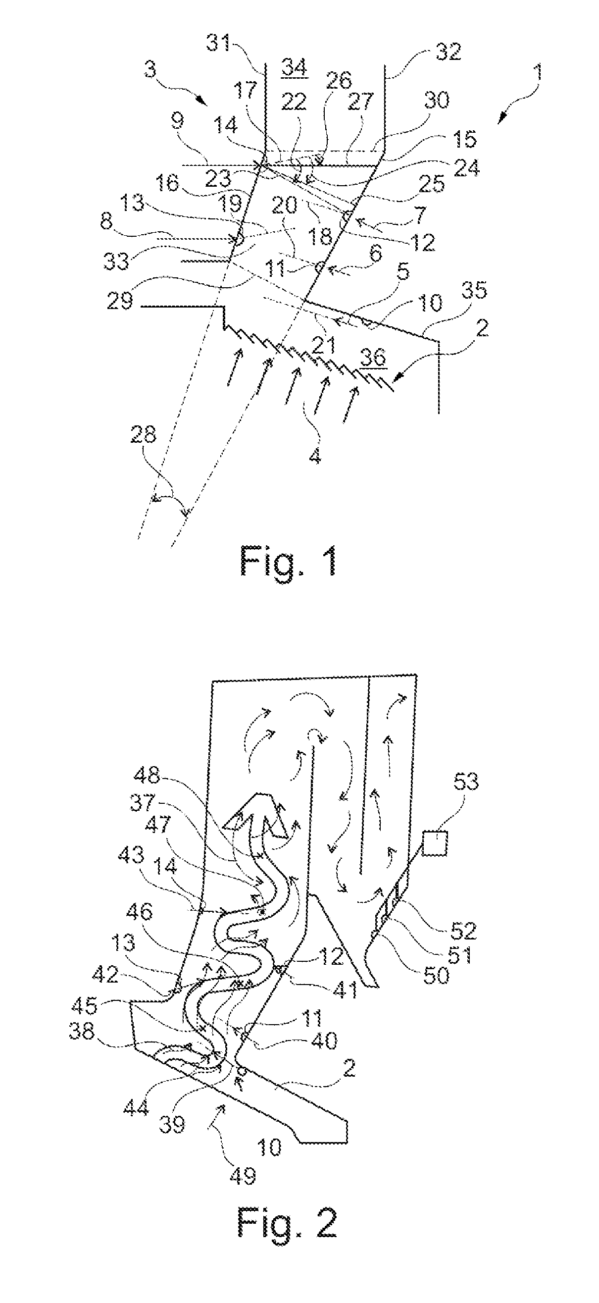
[0028] FIG. 1 is a schematic view of the arrangement of fluid addition points on a combustion plant, and
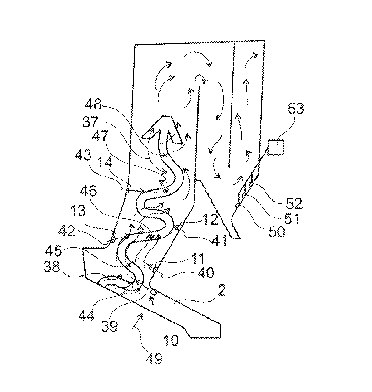
[0029] FIG. 2 is a schematic view of a wavy line of flue gases in a flue gas outlet.
DETAILED DESCRIPTION OF THE PREFERRED EMBODIMENTS
[0030] The combustion plant 1 shown on FIG. 1 has a furnace grate 2 and a flue gas outlet 3. The arrows 4 denote the addition of primary air at the furnace grate 2, and the arrows 5 to 9 denote the addition of secondary air via nozzles. The nozzles 10 to 14 are only schematically denoted. The nozzle 10 is here arranged above the furnace grate 2, and the nozzles 11 and 12 are arranged on a side 15 of the flue gas outlet 3, while the nozzles 13 and 14 are arranged on the opposing side 16 of the flue gas outlet 3.
[0031] The dotted lines 17 to 21 denote the primary nozzle direction of the nozzles 10 to 14.
[0032] With respect to the primary nozzle direction 17, the angle 22 shows the alignment relative to a line 23 connecting the nozzles 12 and 14. The angle 24 shows the alignment of the primary nozzle direction 17 in relation to the shortest connection 25 of the nozzle 14 to the opposing side 15 of the flue gas outlet 3. Finally, the angle 26 shows the primary nozzle direction 17 of the nozzle 14 in relation to a horizontal plane 27 in the flue gas outlet 3.
[0033] The two opposing sides 15 and 16 of the flue gas outlet 3 are at an angle 28 to each other, so that the flue gas outlet 3 conically expands in the area between the access 29 to the flue gas outlet 3 and a transition 30 to perpendicular sides 31 and 32 of the flue gas outlet 3.
[0034] This results in a lower area 33 of the flue gas outlet 3 between the access 29 from the furnace grate 2 to the flue gas outlet 3 and the transition 30 from the area 33 of the flue gas outlet 3 with the inclined sides 15, 16 to the area 34 of the flue gas outlet with perpendicular walls 31 and 32, which is offset relative to this second area 34 between the perpendicular walls 31 and 32.
[0035] The nozzle 10 with its primary nozzle direction 21 is arranged on a wall 35 lying opposite the furnace grate 2, and thus lies in an area 36 above the furnace grate 2 and before the entry into the lower area 33.
[0036] During operation of the combustion plant 1, the nozzles 10 to 14 generate a wavy line 37 of flue gas 38, which arises on the furnace grate 2. Adding secondary combustion air 39 to 43 as the gas to the flue gas 38 produces the wavy line 37 with its reversal points 44 to 48. The primary combustion air 49 is supplied to the combustion plant 1 via the grate 2.
[0037] This makes it possible to add the combustion air in such a way that the flue gas 38 flows on the wavy line 37. A preferred method additionally provides that either the secondary combustion air 39 to 43 or the primary combustion air 49 and the secondary combustion air 39 to 43 be added distributed among the different addition points on the grate 2 or on the nozzles 10 to 14 in varying quantities as a volume flow or mass flow during operation of the combustion plant. The combustion air ratio can here vary during operation of the combustion plant. However, it is advantageous for the combustion air ratio to be held constant.
[0038] Sensors 50, 51 and 52 for NO.sub.x, CO and/or O.sub.2 are connected with a controller 53, so as to optimize the distribution of combustion air comprised of primary combustion air 49 and secondary combustion air 39 to 43 to the individual addition points.
[0039] The burnout can be determined from the measured values ascertained with the sensors 50 to 52, making it possible to adjust the distribution of combustion air to the nozzles so that the burnout per unit time remains nearly constant.
* * * * *
D00000
D00001
XML
uspto.report is an independent third-party trademark research tool that is not affiliated, endorsed, or sponsored by the United States Patent and Trademark Office (USPTO) or any other governmental organization. The information provided by uspto.report is based on publicly available data at the time of writing and is intended for informational purposes only.
While we strive to provide accurate and up-to-date information, we do not guarantee the accuracy, completeness, reliability, or suitability of the information displayed on this site. The use of this site is at your own risk. Any reliance you place on such information is therefore strictly at your own risk.
All official trademark data, including owner information, should be verified by visiting the official USPTO website at www.uspto.gov. This site is not intended to replace professional legal advice and should not be used as a substitute for consulting with a legal professional who is knowledgeable about trademark law.