Device And Method For Mitigating Annular Pressure Buildup In A Wellbore Casing Annulus
ROUSSIE; Gabriel
U.S. patent application number 16/110277 was filed with the patent office on 2019-02-28 for device and method for mitigating annular pressure buildup in a wellbore casing annulus. This patent application is currently assigned to VALLOUREC TUBE-ALLOY, LLC. The applicant listed for this patent is VALLOUREC TUBE-ALLOY, LLC. Invention is credited to Gabriel ROUSSIE.
| Application Number | 20190063191 16/110277 |
| Document ID | / |
| Family ID | 63364119 |
| Filed Date | 2019-02-28 |


| United States Patent Application | 20190063191 |
| Kind Code | A1 |
| ROUSSIE; Gabriel | February 28, 2019 |
DEVICE AND METHOD FOR MITIGATING ANNULAR PRESSURE BUILDUP IN A WELLBORE CASING ANNULUS
Abstract
A device and method are provided for mitigating annular pressure buildup in a wellbore casing annulus of an oil or gas well. The device includes a tubular member including an outer side, a chamber secured around the outer side, the chamber having at least one flexible portion for varying the internal volume of the chamber, at least one reservoir capable of supplying a gas, and a pressure compensator connecting the reservoir and the chamber. The reservoir is able to feed the chamber volume with the gas via the pressure compensator.
| Inventors: | ROUSSIE; Gabriel; (Sugarland, TX) | ||||||||||
| Applicant: |
|
||||||||||
|---|---|---|---|---|---|---|---|---|---|---|---|
| Assignee: | VALLOUREC TUBE-ALLOY, LLC Houston TX |
||||||||||
| Family ID: | 63364119 | ||||||||||
| Appl. No.: | 16/110277 | ||||||||||
| Filed: | August 23, 2018 |
Related U.S. Patent Documents
| Application Number | Filing Date | Patent Number | ||
|---|---|---|---|---|
| 62549315 | Aug 23, 2017 | |||
| Current U.S. Class: | 1/1 |
| Current CPC Class: | E21B 34/063 20130101; E21B 34/06 20130101; E21B 33/00 20130101; E21B 41/00 20130101 |
| International Class: | E21B 41/00 20060101 E21B041/00; E21B 34/06 20060101 E21B034/06 |
Claims
1. A device for mitigating annular pressure buildup in a wellbore casing annulus of an oil or gas well, comprising: a tubular member comprising an outer side, a chamber secured around said outer side, said chamber having at least one flexible portion for varying the internal volume of the chamber, at least one reservoir capable of supplying a gas, a pressure compensator connecting said at least one reservoir and said chamber, and wherein said at least one reservoir is able to feed said chamber with said gas via the pressure compensator.
2. A device for mitigating annular pressure buildup according to claim 1, wherein said chamber comprises an envelope disposed around said outer side, said outer side and said envelope forming said chamber, and wherein said envelope comprises said at least one flexible portion.
3. A device for mitigating annular pressure buildup according to claim 2, wherein said envelope includes a first flange and a second flange, said flanges being arranged at a distance from one another along said tubular member, and wherein said flexible portion is an elastic membrane that is disposed radially around said outer side, that extends axially along the tubular member and that is fastened at its axial extremities to said two flanges.
4. A device for mitigating annular pressure buildup according to claim 3, wherein said elastic membrane is configured to produce a uniform rise or decrease of said chamber volume.
5. A device for mitigating annular pressure buildup according to claim 3, wherein said elastic membrane is transversally or longitudinally lobe-shaped.
6. A device for mitigating annular pressure buildup according to claim 3, wherein said flanges and said elastic membrane are made of steel.
7. A device for mitigating annular pressure buildup according to claim 3, wherein said tubular member comprises reinforcement and holding means fastening said elastic membrane.
8. A device for mitigating annular pressure buildup according to claim 1, wherein said chamber includes at least one tube, wherein said tube comprises said at least one flexible portion.
9. A device for mitigating annular pressure buildup according to claim 8, wherein said one or more tubes are straight tubes arranged parallel to said tubular member or tubes wound around said tubular member.
10. A device for mitigating annular pressure buildup according to claim 1, wherein said pressure compensator allows gas to flow from said at least one reservoir to said chamber when said external pressure increases.
11. A device for mitigating annular pressure buildup according to claim 1, wherein said pressure compensator is an air pressure regulator adapted to high pressure.
12. A device for mitigating annular pressure buildup according to claim 1, wherein said reservoir is selected from bottles, cylinders or any other recipients suitable for containing gas under pressure.
13. A device for mitigating annular pressure buildup according to claim 1, wherein said at least one reservoir is a cryogenic storage dewar.
14. A device for mitigating annular pressure buildup according to claim 1, wherein said chamber comprises a burst disk to vent supply gas when the pressure prevailing in the chamber exceeds a predetermined limit.
15. A device for mitigating annular pressure buildup according to claim 1, wherein the said tubular member is a casing tube.
16. A method of mitigating pressure buildup within a wellbore casing annulus of an oil or gas well, wherein said method comprises: providing at the ground level a device for mitigating annular pressure buildup according to claim 1, lowering said device in the wellbore, letting said pressure compensator allow flow of said gas from the at least one reservoir into the chamber, so as to at least partially compensate an increase of external pressure due to the lowering of said device.
17. A method according to claim 16, comprising filling said reservoir with said gas in pressurized form or in liquid form, before lowering said device in the wellbore.
18. A method according to claim 17, wherein said gas is inert gas, such as nitrogen.
19. A method according to claim 16, further comprising filling said reservoir with a gas generator capable of producing said gas, before lowering said device in the wellbore.
20. A method according to claim 19, wherein said gas generator is a propellant and wherein said gas is produced by said propellant.
21. A method according to claim 16, further comprising adjusting the pressure prevailing in said chamber to a value substantially equal to ground level pressure before lowering said device in the wellbore.
22. A method according to claim 16, wherein said pressure compensator lets said gas flow from the at least one reservoir to the chamber when the external pressure is above a specified pressure.
23. A method according to claim 16, wherein said flexible portion deforms when the pressure difference between the external pressure and the pressure inside said chamber exceeds a specified value.
Description
[0001] This invention relates generally to mitigation of temperature-related pressure buildup in the trapped annulus of an oil or gas well, and specifically to systems and methods for mitigating such annular pressure buildup, wherein such systems and methods typically employ production and/or tieback casing having one or more pressure mitigating chambers.
[0002] Annular Pressure Buildup (APB) is the pressure generated by the thermal expansion of trapped wellbore fluids as they are heated. Other terms are also used to describe this occurrence such as "trapped annular pressure" and "annular fluid expansion."
[0003] Sometimes, a section of formation must be isolated from the rest of the well with casing to withstand the extreme pressures prevailing at depth. Casing is run to protect or isolate formations adjacent to the wellbore. Most land wells and many offshore platform wells are equipped with wellheads that provide access to every casing annulus. Any observed pressure increase can be bled off into atmosphere, thus preventing the damaging effects of annular pressure buildup from occurring. On the contrary, most subsea wellhead installations do not have access to each casing annulus.
[0004] When casing strings are heated by the production of hot fluid from the lower hotter sections of the wells, the trapped fluids expand. If one or more annuli are sealed, a steep pressure increase may result.
[0005] The consequences of an annular pressure buildup without the benefit of bleed off into atmosphere can lead to collapse the tubing or rupture the production casing.
[0006] Some methods to mitigate annular pressure buildup have involved placing of a compressible fluid, such as nitrogen (N.sub.2), in the trapped annulus during the cement work to limit the pressure buildup associated with expansion of the trapped fluid such as described in U.S. Pat. No. 4,109,725. While such methods can help limiting the pressure in the annulus by liquefying the compressible fluid, the resulting pressures can still be quite high.
[0007] Insulating fluid has sometimes been placed in the casing annuli in an effort to limit the transfer of heat due to convection from the wellbore to the fluids in the trapped casing annuli.
[0008] In document U.S. Pat. No. 7,096,944, annular pressure buildup mitigation efforts have involved strapping a compressible solid material, such as foam or hollow particles, to the outside of the inner casing string to accommodate expansion of the fluids in the annulus by effectively increasing the volume in the annulus as the solid material compresses.
[0009] However, this system is not reversible. If the fluids contracts when the well cools down, a vacuum is created on the outside of the casing. Thus, compensation is reduced between internal and external pressure.
[0010] Another approach described in US 20070114033 for mitigating annular pressure buildup is to place a fluid or other material such as methyl methacrylate in the annulus that will shrink when activated by heat.
[0011] Burst disks also have been employed to act as a pressure relief means and to allow the heated fluid in the annulus to vent through the disc. In U.S. Pat. No. 8,066,074, burst disks are used in combination with expandable chambers comprising pistons along with highly pressurized neutral gas. However, the pistons have to be strongly pre-stressed at the surface, which request prudence during manipulations, and may be unsafe. Moreover, efficiency of piston chambers is limited by hydrostatic pressure when deployed.
[0012] Therefore, it is an object of the invention to provide a device for mitigating annular pressure buildup in a wellbore casing annulus of an oil or gas well. In one embodiment, the device for mitigating annular pressure buildup comprises: [0013] a tubular member comprising an outer side, [0014] a chamber secured around said outer side,
[0015] wherein [0016] said chamber has at least one flexible portion for varying the internal volume (V1) of the chamber.
[0017] The chamber is intended to be immersed in an external fluid, and to be sealed and filled with gas.
[0018] The flexible portion of the chamber may deform under the effect of the pressure difference between the external pressure (Pe) and the chamber pressure (P1). The deformation of the flexible portion accommodates, at least partially, the remaining difference between external pressure (Pe) and chamber pressure (P1). Furthermore, when the deformation of the flexible portion is inward, so that the internal volume (V1) of the chamber diminishes, the space available in the surrounding annulus increases and the external pressure decreases.
[0019] In a preferred embodiment, the chamber comprises an envelope disposed around the outer side of the tubular member and the envelope comprises the at least one flexible portion. The outer side of the tubular member and the envelope form said chamber. More specifically, the envelope covers a portion of the outer side of the tubular member and the internal volume (V1) of the chamber is defined by this portion and the envelope.
[0020] In such an embodiment, the envelope may include a first flange and a second flange and the flanges are arranged at a distance from one another along the tubular member. The flexible portion may be an elastic membrane that is disposed radially around the outer side, that extends axially along the tubular member and that is fastened at its axial extremities to the two flanges. The elastic membrane is preferably fastened in a leak-tight manner. The flanges may be made of steel. Advantageously, the elastic membrane is configured to produce a uniform rise or decrease of said chamber volume. In particular, the elastic membrane may have a shape that is geometrically adapted to achieve this effect.
[0021] Advantageously, the elastic membrane is transversally or longitudinally lobe-shaped. When the membrane has longitudinal lobes, the number of said lobes is advantageously between 3 and 10.
[0022] In a preferred embodiment, the elastic membrane is made of steel.
[0023] The tubular member may comprise reinforcement and holding means fastening said elastic membrane.
[0024] Optionally or in combination, said chamber may also include one or more tubes, such as straight tubes arranged parallel to the tubular member or tubes wound around the tubular member, wherein said at least one of tubes comprises said at least one flexible portion.
[0025] The device further comprises: [0026] at least one reservoir capable of supplying a gas, [0027] a pressure compensator connecting said at least one reservoir and said chamber, and
[0028] wherein said at least one reservoir is able to feed said chamber with said gas via the pressure compensator.
[0029] The pressure compensator allows gas to flow from the reservoir to the chamber when an external pressure (Pe) increases. Typically, the pressure compensator allows gas to flow into the chamber when the external pressure is above a specified pressure. The pressure compensator may be an air pressure regulator adapted to handle external pressure.
[0030] The reservoir is configured to be filled with said gas or a generator of said gas.
[0031] The reservoir is capable of supplying a specified quantity of said gas in use.
[0032] The reservoir is preferable capable of withstanding inner pressures up to at least 5 ksi (34.5 MPa).
[0033] The reservoir may be a bottle, a cylinder or any other recipient suitable for containing gas under pressure.
[0034] The gas supplied by the reservoir may be inert gas, such as nitrogen (N.sub.2).
[0035] In an alternative embodiment, the reservoir is a cryogenic storage dewar. Such a reservoir is suitable for containing liquid nitrogen.
[0036] In another alternative embodiment, the reservoir is capable of containing a gas generator, such as a liquid or solid propellant.
[0037] The chamber may comprise a burst disk to vent supply gas when the pressure (P1) prevailing in the chamber exceeds a predetermined limit.
[0038] The tubular member may be a casing tube, such as a production or tieback casing tube.
[0039] The external fluid may be brine.
[0040] It is a further object of the invention to provide a method of mitigating pressure buildup within a wellbore casing annulus of an oil or gas well. Such a method comprises: [0041] providing at ground level a device for mitigating annular pressure buildup as defined above, [0042] preferably adjusting the pressure prevailing in said chamber to a value substantially equal to ground level pressure before lowering said device in the wellbore, [0043] lowering said device in the wellbore, [0044] letting the pressure compensator allow flow of said gas from the at least one reservoir into the chamber, so as to at least partially compensate an increase of external pressure (Pe) due to the lowering of said device.
[0045] Before lowering the device in the wellbore, the reservoir is filled with said gas in pressurized form or in liquid form, or with a gas generator capable of producing said gas.
[0046] Advantageously, the reservoir is filled with said gas or said gas generator so as to allow the supply of a specified quantity of said gas in use, preferably at least during production.
[0047] The gas may be inert gas, such as nitrogen. The gas pressure in the reservoir is may be between 3 and 6 ksi (20.7 and 41.4 MPa) when the reservoir is filled with gas under pressure. The gas pressure is much lower, and may be close to atmospheric pressure, when the reservoir is a dewar containing liquid inert gas, such as nitrogen.
[0048] The gas generator may be a propellant and said gas is produced by said propellant. The propellant may be solid, such as sodium azide with potassium nitrate or an ammonium perchlorate composite, or liquid, such as hydrogen peroxide, hydrazine or nitrous oxide, or any combination thereof. The propellant may mechanically be activated to release gas during the lowering operation.
[0049] The pressure prevailing in said chamber at ground level is deemed to be substantially equal to ground level pressure when it departs from the latter by less than a factor of 2.
[0050] The device mitigates the increase of external pressure (Pe) caused by its lowering in the wellbore. This mitigation is obtained by at least partial compensation of the increase in internal pressure. The mitigation is more specifically obtained by the flow of said gas from the reservoir into the chamber that counter-balances the increase in external pressure.
[0051] Typically, the pressure compensator lets said gas flow from the reservoir to the chamber when the external pressure increases above ground level values.
[0052] In a possible embodiment of the invention, the reservoir initially contains a quantity of gas such that the gas provided by the reservoir continues to flow from the reservoir to the chamber during production if the external pressure increases further in the wellbore casing annulus due to the high temperature reached during production. In this manner, the device extends the mitigation of the difference between external pressure and chamber pressure. Some of the gas contained in the chamber may advantageously be allowed to flow back in the reservoir if the external pressure increases even further.
[0053] The compliance and stiffness of the flexible portion are selected to allow a variation in the internal volume (V1) of the chamber according to the difference between the pressure (P1) inside the chamber and the pressure (Pe) outside the chamber.
[0054] The flexible portion deforms when chamber internal pressure (P1) significantly differs from the external pressure (Pe). Part of the pressure difference is compensated by the change in internal volume (V1) resulting from the deformation of the flexible portion and the remaining pressure difference is mechanically absorbed by the deformation of the flexible portion.
[0055] The deformation adds a mechanical contribution to the compensation effect of the gas provided by the reservoir. The pressure-balancing effect of the gas from the reservoir and the mechanical pressure-balancing effect of the deformation combine to mitigate the pressure exerted on said tubular member.
[0056] In a possible embodiment, the flexible portion of the chamber deforms when the pressure difference between the external pressure (Pe) and the pressure (P1) inside the chamber exceeds a specified value.
[0057] When the external pressure increases in the wellbore casing annulus due to the high temperature reached during production, said flexible portion deforms to partially balance the difference between external pressure (Pe) and chamber pressure (P1).
[0058] When the external pressure decreases in the wellbore casing annulus due to the decrease in temperature reached during production interruption, said flexible portion deforms again to partially balance the difference between external pressure (Pe) and chamber pressure (P1).
[0059] The deformation of said flexible portion is typically inwards, that is towards the tubular member, when the external pressure increases and outwards, that is away of the tubular member, when the external pressure decreases.
[0060] Other advantages and features of the invention will emerge upon examining the detailed description of embodiments, which are in no way limiting, and in view of the appended drawings wherein:
[0061] FIG. 1 is a sectional side view of a wellbore including crushable foams according to prior art to mitigate annular pressure buildup,
[0062] FIG. 2 is a side view of a tubular member provided with a device for mitigating annular pressure buildup according to the invention,
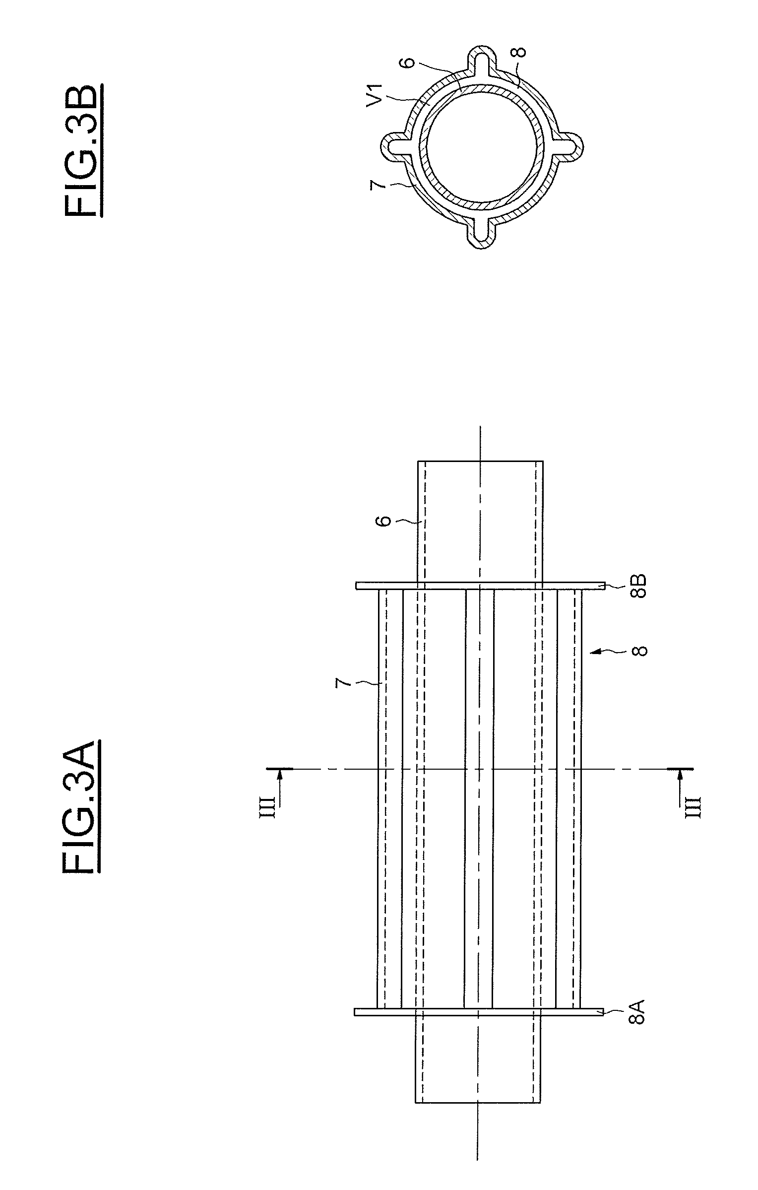
[0063] FIGS. 3A and 3B are side view and sectional front view, respectively, of a tubular member and a part of a device according to one embodiment of the invention, and
[0064] FIG. 4A is a graph of external pressure Pe and external temperature Te in a wellbore annulus, and chamber pressure P1 and reservoir inner pressure P2 in a device for mitigating annular pressure buildup according to the invention, during deployment and production.
[0065] FIG. 4B is a graph of external pressure Pe in a wellbore annulus, and chamber volume V1, chamber pressure P1 and reservoir inner pressure P2 in a device for mitigating annular pressure buildup according to the invention, during deployment and production.
[0066] FIG. 1 shows a sectional side view of a wellbore according to the state of the art having several coaxial annuli. As shown in FIG. 1, wellbore 1 penetrates subterranean formation 2. Within wellbore 1, concentrically placed casing strings 30 define annuli 3A, 3B and 3C. The casing strings are made of one or more casing tubes and are usually much longer than their diameter. Concrete 31 is inserted in the outer annuli 3B and 3C and close them at their bottom end. A production tubing 4 is inserted in the arrangement of casing strings. While shown with two concentric annuli, depending on the length of wellbore 1, any number of concentric annuli may be present. Annulus 3A, which is defined between the innermost casing surface and production tubing 4, extends through most of the length of wellbore 1 and maintains fluid communication with the head of wellbore 1. Although FIG. 1 shows wellbore 1 as having a vertical section, it is to be recognized that any wellbore orientation may be possible.
[0067] In the process of drilling and servicing wellbore 1, fluids, such as drilling fluid or any fluid from the formation, such as brine, may accumulate within annuli 3B and 3C.
[0068] Annuli are often sealed at their upper ends as well, thereby trapping the annular fluid within a confined space. As explained above, when annuli 3B and 3C are sealed at both their upper and lower ends, a pressure increase can occur upon the trapped annular fluid undergoing thermal expansion due to exposure to high-temperature production fluids. Through this phenomenon, the accumulated annular fluid can possibly lead to annular pressure buildup.
[0069] Known pressure-collapsible materials such as hollow spheres and syntactic foam, shown by the numerical reference 5 in FIG. 1, can mitigate annular pressure buildup by providing available space for the annular fluid upon their collapse. Such materials are limited, however, in that they are only effective for one pressurization cycle. That is, once they have collapsed in response to a pressure increase, they are no longer effective to further mitigate the pressure increase. Additionally, the pressure for initiating their collapse may be above a threshold pressure at which casing damage begins to occur. Additionally, when temperature decreases, trapped fluid volume decreases accordingly. Pressure will decrease to the point that a vacuum cap may form in place of the collapsed volume of material. This vacuum may be detrimental to the well integrity.
[0070] Referring to FIG. 2, a device for mitigating annular pressure buildup according to a preferred embodiment of the invention is represented. The device is secured to a tubular member 6, such as a wellbore casing section made of pipe body. In use, the device is mainly immersed in wellbore fluids, such as brine, having an external pressure Pe.
[0071] In this embodiment, an elastic membrane 7 is mounted around the tubular member 6 and at a specified distance from the surface of the tubular member 6. This elastic membrane 7 is preferably disposed radially around the outer side of the tubular member 6, and extends axially along the tubular member 6. The device further includes a first flange 8A and a second flange 8B at a distance from one another and secured to the tubular member 6 in a leak-tight manner. Said flanges are preferably made of steel and welded to the tubular member 6. The elastic membrane 7 is attached in a leak-tight manner to the two flanges 8A and 8B at its axial extremities. The space located between the elastic membrane 7, the tubular member 6, and the two flanges 8A and 8B forms a sealed chamber 8, having a chamber volume V1. Said chamber 8 has an internal pressure P1 in use.
[0072] At least one reservoir 9, having a volume V2, capable of containing a specified quantity of gas, such as inert gas such as nitrogen (N.sub.2), or of a gas generator, is rigidly connected to a pressure compensator 10. In one embodiment of the invention, the pressure compensator 10 may be an air pressure regulator adapted to handle the external pressure, which typically varies between 3 ksi (20.7 MPa) and 20 ksi (137.9 MPa), and more typically between 5 ksi (34.5 MPa) and 15 ksi (103.4 MPa). This reservoir 9 is able to let gas flow into the chamber 8 through the pressure compensator 10.
[0073] In another embodiment, liquid state of nitrogen is used in the reservoir, which therefore may be a dewar flask. Volume needed is advantageously less than one liter and generates much more volume compensation capacity. After installation, gas would slowly vaporize and flow in the chamber 8. This embodiment advantageously includes a heat exchanger sized to absorb heat at a relevant pace from the environment. Moreover, this embodiment advantageously allows to reduce the size of the reservoir.
[0074] In an alternative embodiment, the reservoir may contain a gas generator cartridge using solid propellant such as sodium azide (NaN.sub.3) with potassium nitrate (KNO.sub.3) or ammonium perchlorate composite propellant. An alternative to solid propellant could be liquid propellant selected among hydrogen peroxide, hydrazine, or nitrous oxide, or any combination thereof, that may mechanically be activated to release gas during the lowering operation.
[0075] FIG. 3A illustrates a side view of a section of a tubular member 6 partially covered by parts of a device according to the invention. The parts of device shown include an elastic membrane 7, the first flange 8A and the second flange 8B. FIG. 3B shows a view through section III of the elastic membrane 7. In the embodiment of the invention illustrated in FIGS. 3A and 3B, the elastic membrane 7 includes four lobes. The transversally lobe-shaped membrane is advantageously adapted for reinforcement and holding means (not represented) used in the fastening of the elastic membrane 7 to the tubular member 6. The shape of the elastic membrane 7 is designed according to the compliance needs in volume, and allows a uniform radial deformation when submitted to a differential pressure between chamber internal pressure P1 and external pressure Pe. The compliance needs in volume may be between 0.5 gal/foot (6.2 liter/m) and 4 gal/foot (49.7 liter/m). It also allows having a higher chamber pressure P1 than external pressure Pe when installed. The elastic membrane has a stiffness that allows having a lower chamber internal pressure P1 than external pressure Pe at the nominal external temperature when maximal compensation is needed. In this manner, the pressure exerted on the tubular member is lower than the external pressure and thereby reduces the risk of deformation or collapse of the tubular member.
[0076] The flanges and the elastic membrane are preferably made of steel so as to achieve high values of resistance to pressure. In that case, the thickness of the elastic membrane may be between 1/16 inch and 3/16 inch to provide resistance to pressure and flexibility.
[0077] FIGS. 4A and 4B provide example values for external pressure Pe, external temperature Te, chamber pressure P1 and volume V1, and reservoir pressure P2. The evolutions of these parameters have been represented during two stages, using an arbitrary time scale numbered from 1 to 20. The first stage starts at the ground level. Time 1 to time 9 illustrate the progressive lowering of the device in the wellbore, i.e., its installation. The second stage starts when the device is in its final position. Time 10 to time 20 represent a period of production in the wellbore.
[0078] During the installation (times 1 to 9), external pressure Pe significantly rises due to hydrostatic pressure. At the same time, the reservoir fills the chamber volume V1, thus simultaneously raising internal chamber pressure P1 and lowering reservoir pressure P2, until around 4.5 ksi (31 MPa) each at the end of the stage.
[0079] As illustrated in FIG. 4B, the internal chamber volume V1 increases significantly, i.e., from 5 L up to 8.4 L in this example, and as a consequence, provides more expansion compensation ability once the annulus is closed. However, depending on the pressure difference, the internal chamber volume V1 does not necessarily increase during the installation.
[0080] While producing (times 10 to 20), external temperature dramatically increase from 20.degree. C. to 80.degree. C., classically expanding the volume of trapped fluids, typically including brine, within the external annulus, following the annular pressure buildup phenomenon above described. The elastic membrane, which closes the chamber 8 having the internal pressure P1, compresses under the effect of external pressure Pe, thus, resulting in the slight increase of internal pressure P1, combined with a steep fall of the internal chamber volume V1. Space has advantageously rose in the external annulus, which also advantageously reduces the external pressure Pe elevation, and finally mitigates the annular pressure buildup.
[0081] In the example of FIGS. 4A and 4B, the internal chamber volume V1 increases during the installation stage and decreases during the operation stage.
[0082] The proposed device and method are reversible since chamber volume V1 springs back to its installation bottom hole capacity when external temperature drops. In case the device needs to be recovered back to the surface and gas vented out during the process, the device may be reconditioned and the reservoir may be refilled in order to re-use the device just as if it was for the first time.
[0083] Safety may advantageously be improved by using a robust gas container for the transportation and manipulation of pressurized gas in steel bottles.
[0084] In an alternative embodiment, several devices of the invention may be used along the casing string, typically 50 to 200, to accommodate the whole annulus volume.
[0085] In such an embodiment, reservoirs could be connected together in series and fed from ground level. Thus, they would advantageously provide more gas supply for deepest chambers.
* * * * *
D00000
D00001
D00002
D00003
D00004
XML
uspto.report is an independent third-party trademark research tool that is not affiliated, endorsed, or sponsored by the United States Patent and Trademark Office (USPTO) or any other governmental organization. The information provided by uspto.report is based on publicly available data at the time of writing and is intended for informational purposes only.
While we strive to provide accurate and up-to-date information, we do not guarantee the accuracy, completeness, reliability, or suitability of the information displayed on this site. The use of this site is at your own risk. Any reliance you place on such information is therefore strictly at your own risk.
All official trademark data, including owner information, should be verified by visiting the official USPTO website at www.uspto.gov. This site is not intended to replace professional legal advice and should not be used as a substitute for consulting with a legal professional who is knowledgeable about trademark law.