Cutting Element Assemblies Comprising Rotatable Cutting Elements, Downhole Tools Comprising Such Cutting Element Assemblies, And Related Methods
Bomidi; John Abhishek Raj ; et al.
U.S. patent application number 15/691256 was filed with the patent office on 2019-02-28 for cutting element assemblies comprising rotatable cutting elements, downhole tools comprising such cutting element assemblies, and related methods. The applicant listed for this patent is Baker Hughes, a GE company, LLC. Invention is credited to Alexander Rodney Boehm, John Abhishek Raj Bomidi, Kegan L. Lovelace, William A. Moss, Jr., Jon David Schroder.
| Application Number | 20190063162 15/691256 |
| Document ID | / |
| Family ID | 65434152 |
| Filed Date | 2019-02-28 |
| United States Patent Application | 20190063162 |
| Kind Code | A1 |
| Bomidi; John Abhishek Raj ; et al. | February 28, 2019 |
CUTTING ELEMENT ASSEMBLIES COMPRISING ROTATABLE CUTTING ELEMENTS, DOWNHOLE TOOLS COMPRISING SUCH CUTTING ELEMENT ASSEMBLIES, AND RELATED METHODS
Abstract
Rotatable cutting element assemblies includes a sleeve, a centering element positioned at least partially within the sleeve, a biasing element configured to apply a force against the centering element, and a rotatable cutting element coupled to the centering element and configured to rotate relative to the sleeve. Earth-boring tools include a tool body and at least one rotatable cutting element assembly coupled to the tool body. The at least one rotatable cutting element assembly includes a sleeve fixedly coupled to the tool body, a centering element positioned at least partially within the sleeve, a rotatable cutting element coupled to the centering element, and a biasing element configured to apply a force against the centering element. Methods of forming an earth-boring tool include positioning a centering element within a sleeve, fixedly coupling the sleeve to a tool body, and coupling a rotatable cutting element to the centering element.
| Inventors: | Bomidi; John Abhishek Raj; (Spring, TX) ; Moss, Jr.; William A.; (Conroe, TX) ; Schroder; Jon David; (The Woodlands, TX) ; Boehm; Alexander Rodney; (Wheat Ridge, CO) ; Lovelace; Kegan L.; (Houston, TX) | ||||||||||
| Applicant: |
|
||||||||||
|---|---|---|---|---|---|---|---|---|---|---|---|
| Family ID: | 65434152 | ||||||||||
| Appl. No.: | 15/691256 | ||||||||||
| Filed: | August 30, 2017 |
| Current U.S. Class: | 1/1 |
| Current CPC Class: | E21B 10/43 20130101; E21B 10/55 20130101 |
| International Class: | E21B 10/55 20060101 E21B010/55; E21B 10/43 20060101 E21B010/43 |
Claims
1. A rotatable cutting element assembly for an earth-boring tool, comprising: a sleeve comprising a sidewall and a protrusion extending inward from the sidewall; a centering element positioned at least partially within the sleeve and configured to abut against the protrusion; a biasing element configured to apply a force against the centering element toward the protrusion; and a rotatable cutting element coupled to the centering element and configured to rotate relative to the sleeve.
2. The rotatable cutting element assembly of claim 1, wherein: the centering element comprises a bore extending at least partially through the centering element; and the rotatable cutting element comprises a hole extending at least partially through the rotatable cutting element along a central axis of the rotatable cutting element.
3. The rotatable cutting element assembly of claim 2, further comprising a fastener coupling the rotatable cutting element to the centering element using the bore and the hole.
4. The rotatable cutting element assembly of claim 2, wherein the bore extends fully through the centering element and the hole extends fully through the rotatable cutting element.
5. The rotatable cutting element assembly of claim 2, wherein the hole in the rotatable cutting element is a stepped through-hole comprising a first portion that is wider than a second portion, a lip defined at a transition from the first portion to the second portion.
6. The rotatable cutting element assembly of claim 1, wherein: a portion of the centering element protrudes from the sleeve past the protrusion of the sleeve; and the rotatable cutting element comprises a centering surface complementary to an exterior surface of the protruding portion of the centering element.
7. The rotatable cutting element assembly of claim 1, wherein, absent external forces, a gap is defined between a bottom surface of the rotatable cutting element and a top surface of the sleeve.
8. The rotatable cutting element assembly of claim 1, wherein the rotatable cutting element is configured to rotate about its central axis relative to the sleeve.
9. The rotatable cutting element assembly of claim 1, wherein the sleeve comprises a base, further comprising a fastener threaded to the base and extending through at least a portion of the rotatable cutting element and the centering element.
10. The rotatable cutting element assembly of claim 1, further comprising a centering element support positioned between the centering element and the biasing element.
11. An earth-boring tool, comprising: a tool body; and at least one rotatable cutting element assembly coupled to the tool body, the at least one rotatable cutting element assembly comprising: a sleeve fixedly coupled to the tool body; a centering element positioned at least partially within the sleeve; a rotatable cutting element coupled to the centering element and configured to rotate relative to the tool body; and a biasing element configured to apply a force against the centering element.
12. The earth-boring tool of claim 11, wherein the sleeve comprises a sidewall and a protrusion extending inward from the sidewall, the protrusion sized and shaped to maintain the centering element at least partially within the sleeve.
13. The earth-boring tool of claim 11, wherein the sleeve is brazed to the tool body.
14. The earth-boring tool of claim 11, wherein the tool body comprises a fixed blade, and the sleeve is positioned within a pocket in the fixed blade.
15. The earth-boring tool of claim 11, further comprising a fastener coupling the rotatable cutting element to the centering element.
16. The earth-boring tool of claim 15, wherein the fastener extends into a hole formed in the tool body.
17. A method of forming an earth-boring tool, the method comprising: positioning a centering element within a sleeve; positioning a biasing element within the sleeve and adjacent to the centering element; fixedly coupling the sleeve to a tool body within a pocket of the tool body; and coupling a rotatable cutting element to the centering element, the rotatable cutting element rotatable relative to the tool body.
18. The method of claim 17, further comprising attaching a base of the sleeve to a sidewall of the sleeve after positioning the centering element and the biasing element within the sleeve to maintain the centering element and the biasing element within the sleeve.
19. The method of claim 17, wherein coupling the rotatable cutting element to the centering element comprises attaching the rotatable cutting element to a ball with a fastener.
20. The method of claim 19, wherein the rotatable cutting element is rotatable about its central axis relative to the fastener and relative to the tool body.
Description
FIELD
[0001] Embodiments of this disclosure relate generally to rotatable cutting elements for downhole earth-boring tools, earth-boring tools including such cutting elements, and related methods.
BACKGROUND
[0002] Wellbores are formed in subterranean formations for various purposes including, for example, extraction of oil and gas from the subterranean formation and extraction of geothermal heat from the subterranean formation. Wellbores may be formed in a subterranean formation using an earth-boring tool, such as an earth-boring rotary drill bit or a reamer. Different types of earth-boring rotary drill bits are known in the art, including fixed-cutter bits (which are often referred to in the art as "drag" bits), rolling-cutter bits (which are often referred to in the art as "rock" bits), diamond-impregnated bits, and hybrid bits (which may include, for example, both fixed cutters and rolling cutters). Reamers are used to enlarge a wellbore, and may also include one or more cutters. The drill bit or reamer is rotated and advanced into the subterranean formation. Upon rotation, the cutters or abrasive structures thereof cut, crush, shear, and/or abrade away the formation material to form or enlarge the wellbore. A diameter of the wellbore drilled by the drill bit may be defined by the cutting structures disposed at the largest outer diameter of the drill bit or reamer.
[0003] The drill bit or reamer is coupled, either directly or indirectly, to what is referred to in the art as a "drill string," which comprises a series of elongated tubular segments connected end-to-end that extends into the wellbore from the surface of earth above the subterranean formations being drilled. Various tools and components, including the drill bit or reamer, may be coupled together, such as proximate or at the distal end of the drill string at the bottom of the wellbore being drilled. An assembly of tools and components at the end of the drill string is referred to in the art as a "bottom hole assembly" (BHA).
[0004] The drill bit or reamer may be rotated within the wellbore by rotating the drill string from the surface of the formation, or the drill bit or reamer may be rotated with a downhole motor, which is also coupled to the drill string and disposed proximate the bottom of the wellbore. The downhole motor may include, for example, a hydraulic Moineau-type motor having a shaft, to which the drill bit is mounted, that may be caused to rotate by pumping fluid (e.g., drilling mud or fluid) from the surface of the formation down through the center of the drill string, through the hydraulic motor, out from nozzles in the drill bit, and back up to the surface of the formation through the annular space between the outer surface of the drill string and the exposed surface of the formation within the wellbore. The downhole motor may be operated with or without drill string rotation.
[0005] The drill string may include a number of components in addition to a downhole motor and drill bit and/or reamer including, without limitation, drill pipe, drill collars, stabilizers, measuring while drilling (MWD) equipment, logging while drilling (LWD) equipment, downhole communication modules, and other components.
[0006] In addition to drill strings, other tool strings may be disposed in an existing well bore for, among other operations, completing, testing, stimulating, producing, and remediating hydrocarbon-bearing formations.
[0007] Cutting elements used in earth boring tools often include polycrystalline diamond compact (often referred to as "PDC") cutting elements, which are cutting elements that include so-called "tables" of a polycrystalline diamond material mounted to supporting substrates and presenting a cutting face for engaging a subterranean formation. Polycrystalline diamond (often referred to as "PCD") material is material that includes inter-bonded grains or crystals of diamond material. In other words, PCD material includes direct, intergranular bonds between the grains or crystals of diamond material.
[0008] Cutting elements are typically mounted on a drill bit or reamer body by brazing. The body is formed with recesses therein, commonly termed "pockets," for receiving a substantial portion of each cutting element in a manner to present the PCD layer at an appropriate back rake and side rake angle, facing in the direction of intended drill bit or reamer rotation, for cutting in accordance with the drill bit or reamer design. In such cases, a brazing compound is applied between the surface of the substrate of the cutting element and the surface of the recess on the body in which the cutting element is received. The cutting elements are installed in their respective recesses in the body, and heat is applied to each cutting element via a torch to raise the temperature to a point high enough to braze the cutting elements to the bit body in a fixed position, but not so high as to damage the PCD layer.
[0009] Unfortunately, securing a PDC cutting element to a drill bit or reamer restricts the useful life of such cutting element, because the cutting edge of the diamond table and the substrate wear down, creating a so-called "wear flat" and necessitating increased weight-on-bit to maintain a given rate of penetration of the drill bit or reamer into the formation due to the increased surface area presented. In addition, unless the cutting element is heated for removal and then rebrazed with an unworn portion of the cutting edge presented for engaging a formation, more than half of the cutting element is never used.
[0010] Rotatable cutting elements mounted for rotation about a longitudinal axis of the cutting element can wear more evenly than fixed cutting elements, and exhibit a significantly longer useful life without removal from the earth-boring tool. That is, as a cutting element rotates in a body of an earth-boring tool, different parts of the cutting edges or surfaces may be exposed at different times, such that more of the cutting element is used. Thus, rotatable cutting elements may have a longer life than fixed cutting elements.
BRIEF SUMMARY
[0011] In some embodiments, rotatable cutting element assemblies include a sleeve including a sidewall and a protrusion extending inward from the sidewall, a centering element positioned at least partially within the sleeve and configured to abut against the protrusion, a biasing element configured to apply a force against the centering element toward the protrusion, and a rotatable cutting element coupled to the centering element and configured to rotate relative to the sleeve.
[0012] In some embodiments, earth-boring tools include a tool body and at least one rotatable cutting element assembly coupled to the tool body. The at least one rotatable cutting element assembly includes a sleeve fixedly coupled to the tool body, a centering element positioned at least partially within the sleeve, a rotatable cutting element coupled to the centering element and configured to rotate relative to the tool body, and a biasing element configured to apply a force against the centering element.
[0013] In certain embodiments, methods of forming an earth-boring tool include positioning a centering element within a sleeve, positioning a biasing element within the sleeve and adjacent to the centering element, fixedly coupling the sleeve to a tool body within a pocket of the tool body, and coupling a rotatable cutting element to the centering element, the rotatable cutting element rotatable relative to the tool body.
BRIEF DESCRIPTION OF THE DRAWINGS
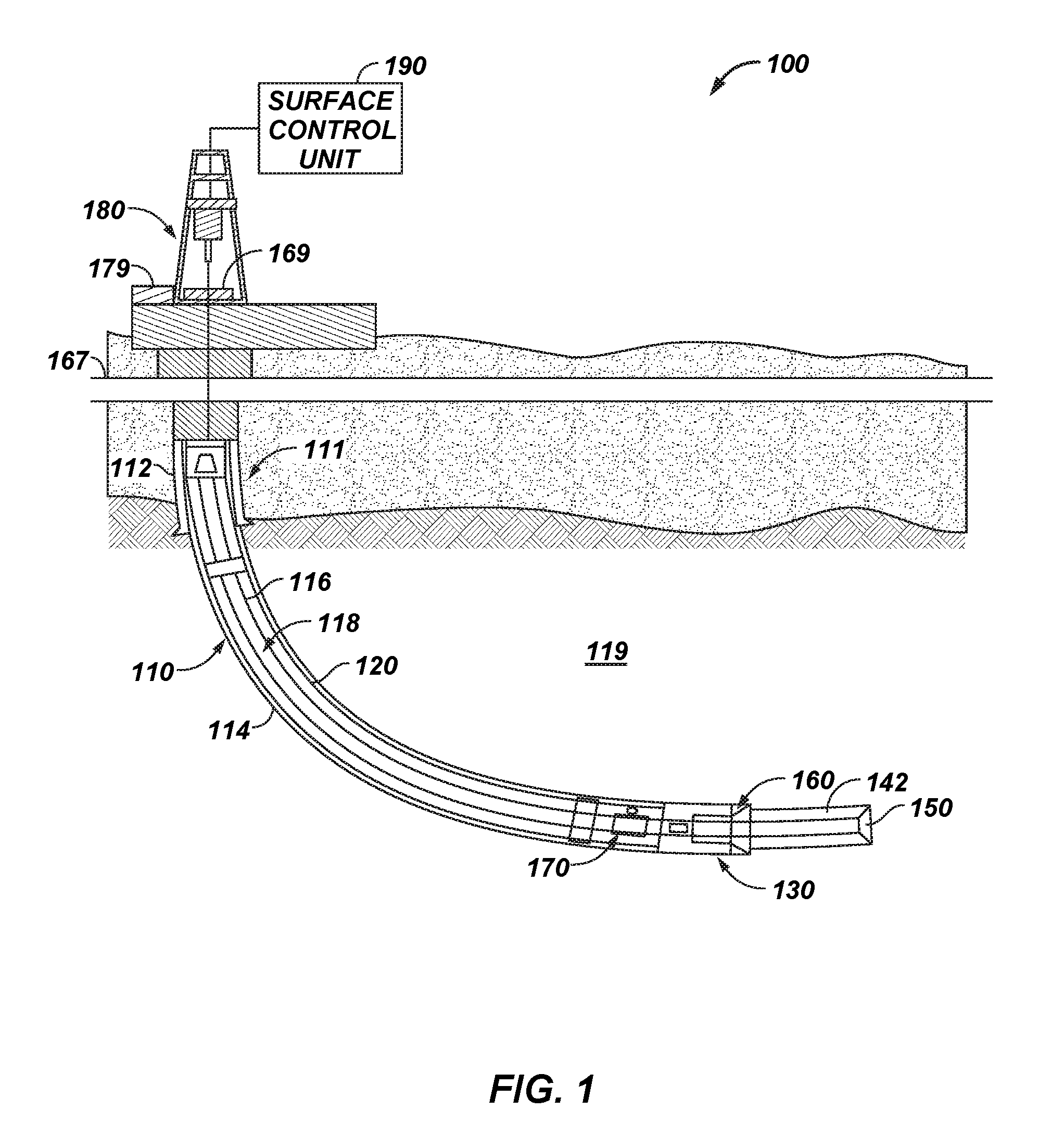
[0014] FIG. 1 is a simplified schematic diagram of a drilling system using cutting element assemblies disclosed herein.
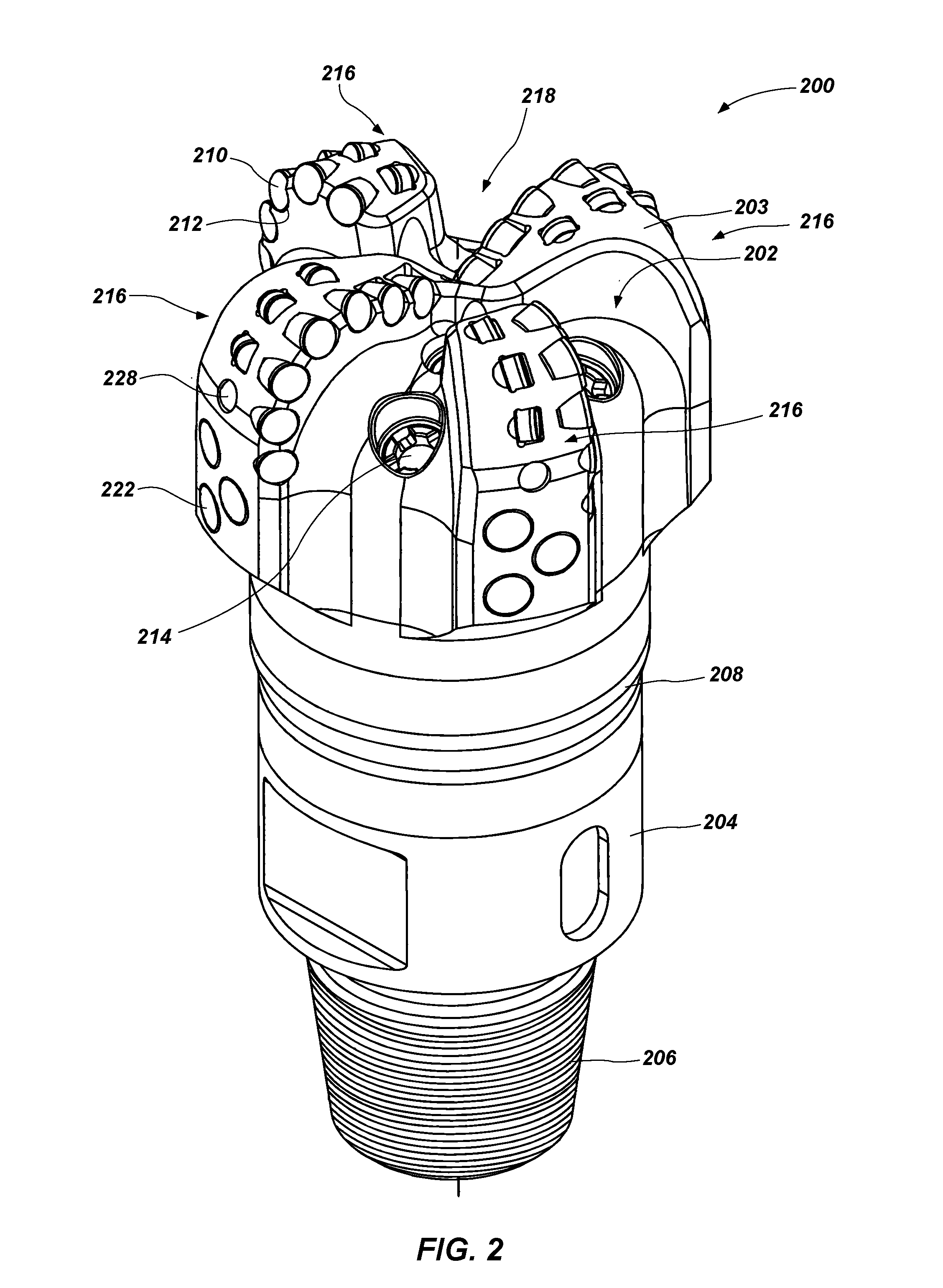
[0015] FIG. 2 is a simplified perspective view of a fixed-blade earth-boring rotary drill bit that may be used in conjunction with the drilling system of FIG. 1.
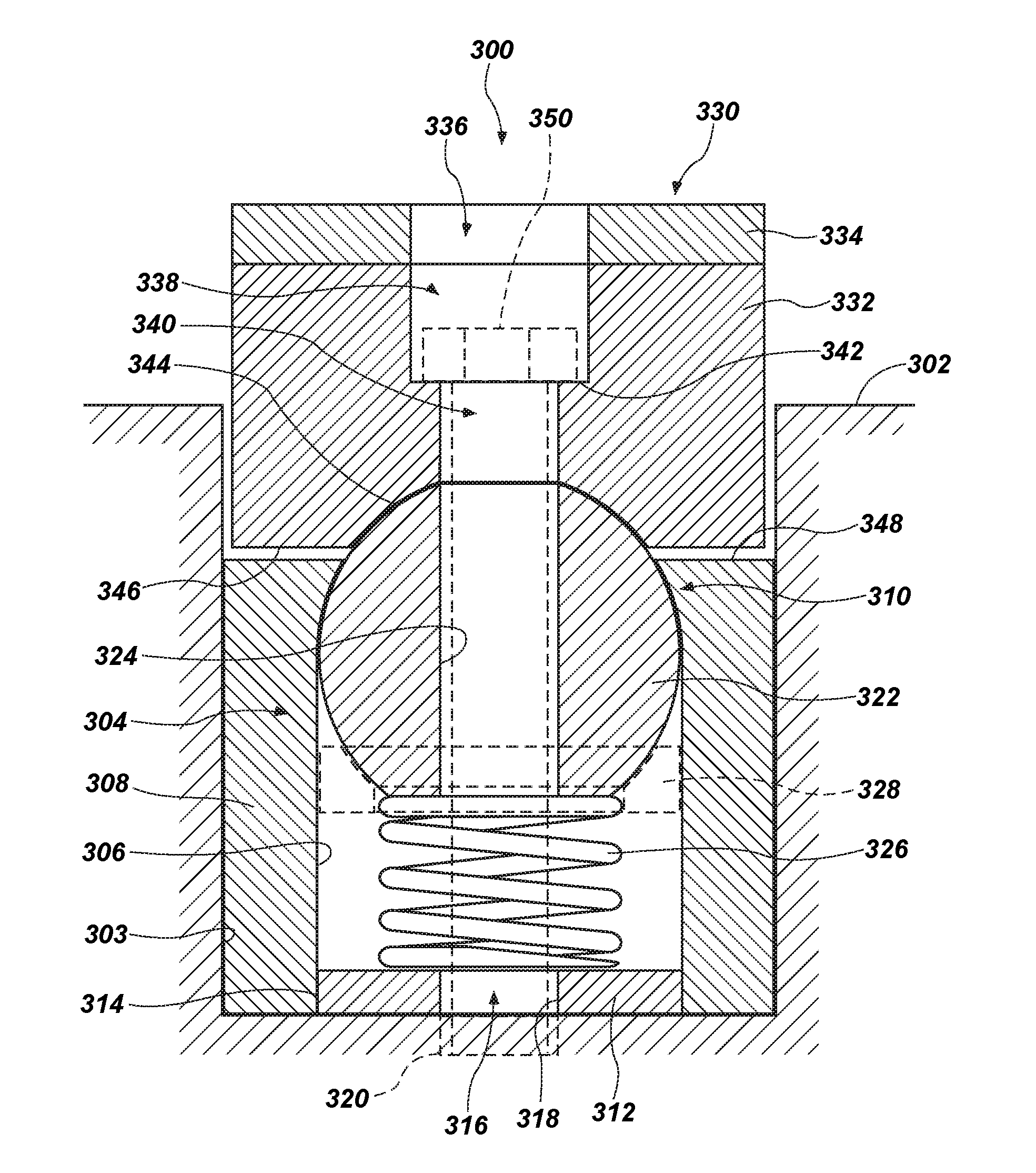
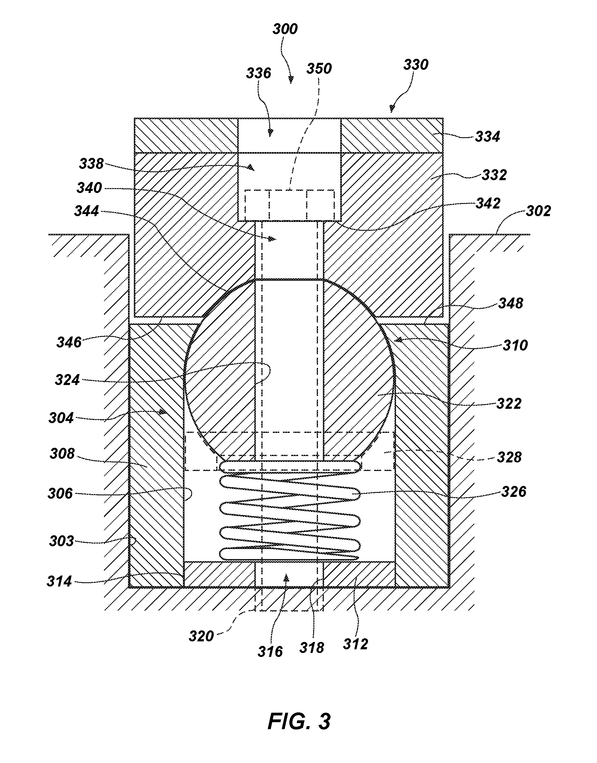
[0016] FIG. 3 is a simplified cross section showing a cutting element assembly according to an embodiment of this disclosure, mounted in a blade of an earth-boring tool, such as in a blade of the fixed-blade earth-boring rotary drill bit of FIG. 2.
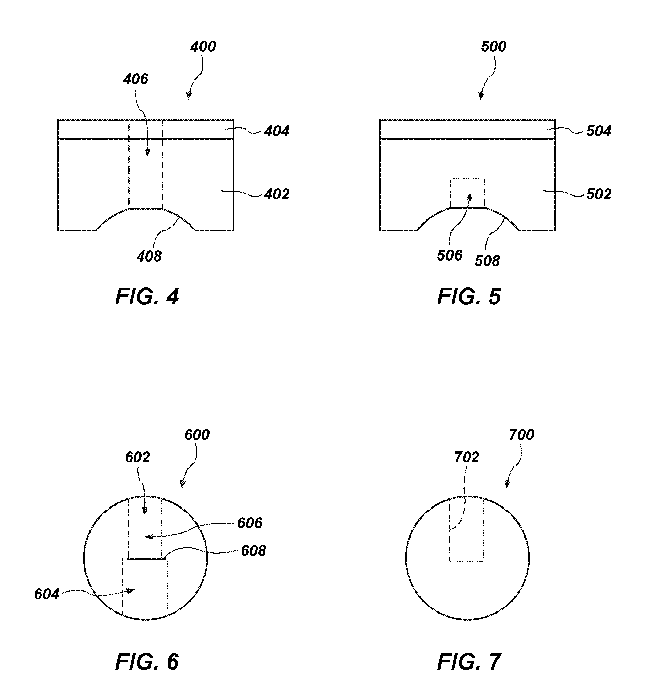
[0017] FIGS. 4 and 5 are simplified cross-sectional views showing additional embodiments of rotatable cutting elements for use in cutting element assemblies.
[0018] FIGS. 6 and 7 are simplified cross-sectional views showing additional embodiments of centering elements for use in cutting element assemblies.
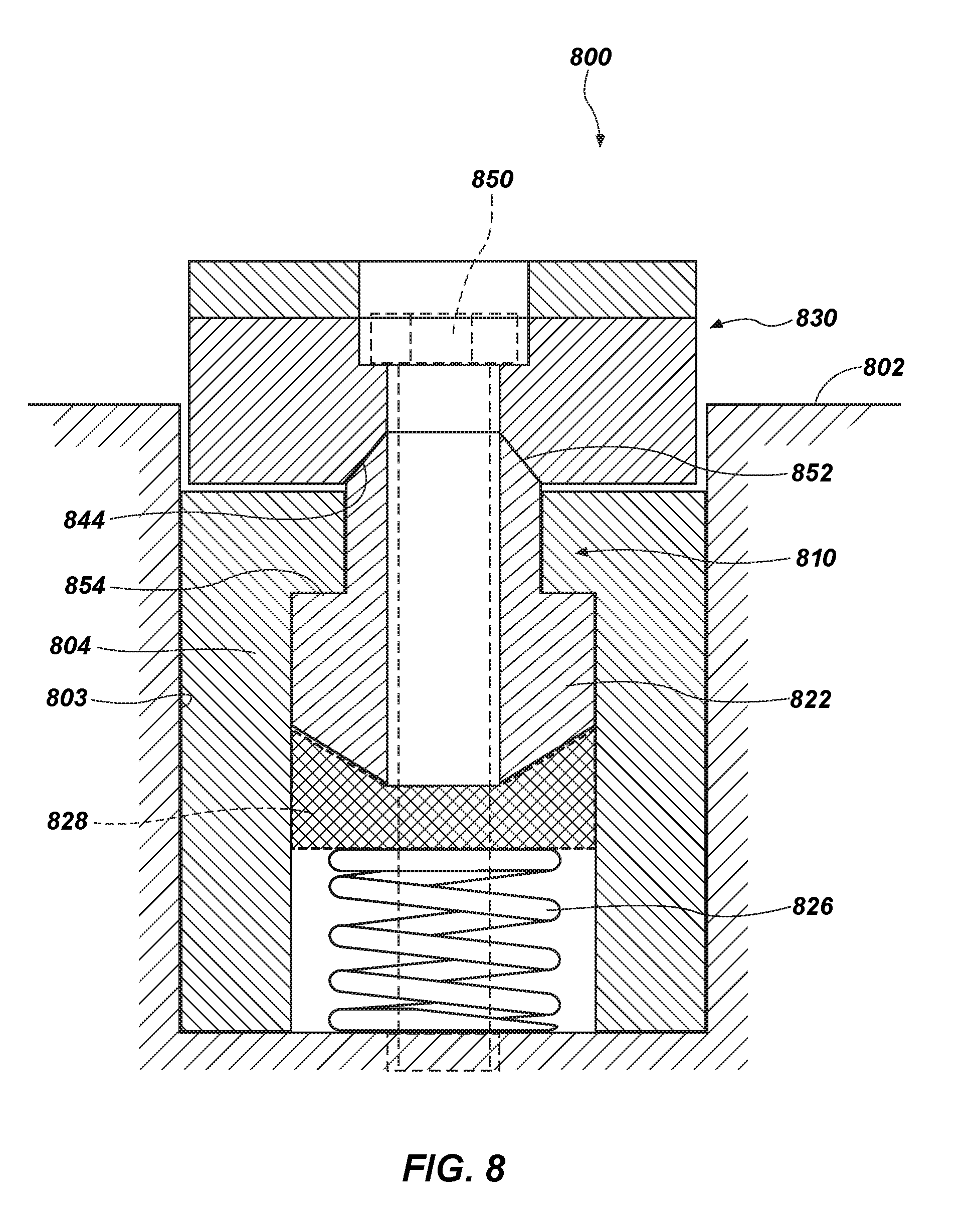
[0019] FIG. 8 is a simplified cross section showing a cutting element assembly according to another embodiment of this disclosure, mounted in a blade of an earth-boring tool, such as in a blade of the fixed-blade earth-boring rotary drill bit of FIG. 2.
DETAILED DESCRIPTION
[0020] The illustrations presented herein are not actual views of any particular cutting assembly, tool, or drill string, but are merely idealized representations employed to describe example embodiments of the present disclosure. The following description provides specific details of embodiments of the present disclosure in order to provide a thorough description thereof. However, a person of ordinary skill in the art will understand that the embodiments of the disclosure may be practiced without employing many such specific details. Indeed, the embodiments of the disclosure may be practiced in conjunction with conventional techniques employed in the industry. Only those process acts and structures necessary to understand the embodiments of the disclosure are described in detail below. Additional conventional acts and structures may be used. Also note, any drawings accompanying the application are for illustrative purposes only, and are thus not drawn to scale. Additionally, elements common between figures may have corresponding numerical designations.
[0021] As used herein, the terms "comprising," "including," "containing," "characterized by," and grammatical equivalents thereof are inclusive or open-ended terms that do not exclude additional, un-recited elements or method steps, but also include the more restrictive terms "consisting of," "consisting essentially of," and grammatical equivalents thereof.
[0022] As used herein, the term "may" with respect to a material, structure, feature, or method act indicates that such is contemplated for use in implementation of an embodiment of the disclosure, and such term is used in preference to the more restrictive term "is" so as to avoid any implication that other compatible materials, structures, features, and methods usable in combination therewith should or must be excluded.
[0023] As used herein, the term "configured" refers to a size, shape, material composition, and arrangement of one or more of at least one structure and at least one apparatus facilitating operation of one or more of the structure and the apparatus in a predetermined way.
[0024] As used herein, the singular forms following "a," "an," and "the" are intended to include the plural forms as well, unless the context clearly indicates otherwise.
[0025] As used herein, the term "and/or" includes any and all combinations of one or more of the associated listed items.
[0026] As used herein, spatially relative terms, such as "upward," "downward," "lower," "bottom," "above," "upper," "top," and the like, may be used for ease of description to describe one element's or feature's relationship to another element(s) or feature(s) as illustrated in the figures. Unless otherwise specified, the spatially relative terms are intended to encompass different orientations of the materials in addition to the orientation depicted in the figures.
[0027] As used herein, the term "substantially" in reference to a given parameter, property, or condition means and includes to a degree that one of ordinary skill in the art would understand that the given parameter, property, or condition is met with a degree of variance, such as within acceptable manufacturing tolerances. By way of example, depending on the particular parameter, property, or condition that is substantially met, the parameter, property, or condition may be at least 90.0% met, at least 95.0% met, at least 99.0% met, or even at least 99.9% met.
[0028] As used herein, the term "about" used in reference to a given parameter is inclusive of the stated value and has the meaning dictated by the context (e.g., it includes the degree of error associated with measurement of the given parameter).
[0029] As used herein, the term "hard material" means and includes any material having a Knoop hardness value of about 1,000 kg.sub.f/mm.sup.2 (9,807 MPa) or more. Hard materials include, for example, diamond, cubic boron nitride, boron carbide, tungsten carbide, etc.
[0030] As used herein, the term "intergranular bond" means and includes any direct atomic bond (e.g., covalent, metallic, etc.) between atoms in adjacent grains of material.
[0031] As used herein, the term "polycrystalline hard material" means and includes any material comprising a plurality of grains or crystals of the material that are bonded directly together by intergranular bonds. The crystal structures of the individual grains of polycrystalline hard material may be randomly oriented in space within the polycrystalline hard material.
[0032] As used herein, the term "earth-boring tool" means and includes any type of tool used for drilling during the formation or enlargement of a wellbore and includes, for example, rotary drill bits, percussion bits, core bits, eccentric bits, bi-center bits, reamers, mills, drag bits, roller-cone bits, hybrid bits, and other drilling bits and tools known in the art.
[0033] FIG. 1 is a schematic diagram of an example of a drilling system 100 using cutting element assemblies disclosed herein. FIG. 1 shows a wellbore 110 that may include an upper section 111 with a casing 112 installed therein and a lower section 114 that is being drilled with a drill string 118. The drill string 118 may include a tubular member 116 that carries a drilling assembly 130 at its bottom end. The tubular member 116 may be coiled tubing or may be formed by joining drill pipe sections. A drill bit 150 (also referred to as the "pilot bit") may be attached to the bottom end of the drilling assembly 130 for drilling a first, smaller diameter borehole 142 in a formation 119. A reamer 160 may be placed above or uphole of the drill bit 150 in the drill string 118 to enlarge the first, smaller diameter borehole 142 to a second, larger diameter borehole 120. The terms wellbore and borehole are used herein as synonyms.
[0034] The drill string 118 may extend to a rig 180 at the surface 167. The rig 180 shown is a land rig for ease of explanation. The apparatus and methods disclosed herein equally apply when an offshore rig is used for drilling underwater. A drive system 169 (e.g., a rotary table or a top drive) may rotate the drill string 118 and the drilling assembly 130, and thus the pilot bit 150 and reamer 160, to respectively form boreholes 142 and 120. The rig 180 may also include conventional devices, such as mechanisms to add additional sections to the tubular member 116 as the wellbore 110 is drilled. A surface control unit 190, which may be a computer-based unit, may be placed at the surface for receiving and processing downhole data transmitted by the drilling assembly 130 and for controlling the operations of various devices and sensors 170 in the drilling assembly 130. A drilling fluid from a source 179 thereof may be pumped under pressure through the tubular member 116, discharged through the pilot bit 150, and returned to the surface via the annular space (also referred to as the "annulus") between the drill string 118 and an inside wall of the wellbore 110.
[0035] During operation, when the drill string 118 is rotated, both the pilot bit 150 and the reamer 160 may rotate. The pilot bit 150 may drill the first, smaller diameter borehole 142, while simultaneously the reamer bit 160 may enlarge the first, smaller diameter borehole borehole 142 to a second, larger diameter borehole 120. The earth's subsurface formation 119 may contain rock strata made up of different rock structures that can vary from soft formations to very hard formations, and therefore the pilot bit 150 and/or the reamer 160 may be selected based on the formations expected to be encountered in a drilling operation.
[0036] FIG. 2 is a perspective view of a fixed-cutter earth-boring rotary drill bit 200 that may be used in conjunction with the drilling system 100 of FIG. 1. For example, the drill bit 200 may be the pilot bit 150 shown in FIG. 1. The drill bit 200 includes a bit body 202 that may be secured to a shank 204 having a threaded connection portion 206 (e.g., an American Petroleum Institute (API) threaded connection portion) for attaching the drill bit 200 to a drill string (e.g., drill string 118, shown in FIG. 1). In some embodiments, the bit body 202 may be secured to the shank 204 using an extension 208. In other embodiments, the bit body 202 may be secured directly to the shank 204.
[0037] The bit body 202 may include internal fluid passageways that extend between the face 203 of the bit body 202 and a longitudinal bore, extending through the shank 204, the extension 208, and partially through the bit body 202. Nozzle inserts 214 also may be provided at the face 203 of the bit body 202 within the internal fluid passageways. The bit body 202 may further include a plurality of blades 216 that are separated by junk slots 218. In some embodiments, the bit body 202 may include gage wear plugs 222 and wear knots 228. A plurality of cutting element assemblies 210 may be mounted on the face 203 of the bit body 202 in cutting element pockets 212 that are located along each of the blades 216. The cutting element assemblies 210 may include PDC cutting elements, or may include other cutting elements. For example, some or all of the cutting element assemblies 210 may be or include a cutting element assembly 300 including rotatable cutting elements, as described below and shown in FIGS. 3-7.
[0038] FIG. 3 is a simplified cross-sectional view showing a cutting element assembly 300 mounted in a blade 302 of an earth-boring tool. The blade 302 may be, for example, one of the blades 216 shown in FIG. 2. The cutting element assembly 300 may be one of the cutting element assemblies 210 shown in FIG. 2. In some embodiments, the blade 302 may be a body of a roller cone, a body of a reamer, or a body of any earth-boring tool or component that may employ a cutting element. Accordingly, the earth-boring tools of this disclosure are not limited to fixed-cutter rotary drill bits.
[0039] The cutting element assembly 300 may include a sleeve 304 secured to the blade 302. For example, the sleeve 304 may be brazed, welded, and/or threaded within a pocket 303 of the blade 302. In other embodiments, the sleeve 304 may be integrally formed with the blade 302, such that there is no physical interface between the sleeve 304 and the blade 302.
[0040] The sleeve 304 may have a generally cylindrical interior surface 306 defined by a sidewall 308. An inward protrusion 310 may extend from a top portion of the sidewall 308, the inward protrusion defining an inner surface coextensive with the generally cylindrical inner surface 306 of the sidewall 308. The sleeve 304 may also include a base 312, which may be integral with or coupled to a bottom portion of the sidewall 308 at an interface 314. By way of example, the base 312 may be welded, brazed, threaded, or press-fit to the sidewall 308 at the interface 314. A central hole 316 may extend at least partially (e.g., fully) through the base 312. An inner surface 318 of the central hole 316 may be threaded. In some embodiments, a hole 320 (shown in broken lines in FIG. 3) may be present in the blade 302 in a position to be aligned with the central hole 316 of the base 312 of the sleeve 304. The hole 320 in the blade 302 may be threaded.
[0041] A centering element 322 may be positioned partially within the sleeve 308 and retained therein by the inward protrusion 310 of the sleeve 304. As used herein, the term "centering element" means and includes structures including an angled upper surface, including structures having a substantially spherical, hemispherical, tapered, or ellipsoid shape, for example. The inner surface of the inward protrusion 310 may have a shape corresponding to an exterior surface the centering element 322, such as an arcuate inner surface corresponding to a ball-shaped centering element 322, for example. A bore 324 may generally centrally extend through the centering element 322. A top portion of the centering element 322 may protrude out of the sleeve 304 past the inward protrusion 310. The generally cylindrical interior surface 306 of the sidewall 308 may have a diameter that is at least as large as the largest diameter of the centering element 322, while the inward protrusion 310 may have a smallest inner diameter that is smaller than the largest diameter of the centering element 322. Thus, the inward protrusion 310 may retain a majority portion of the centering element 322 within the sleeve 304.
[0042] A biasing element 326 (e.g., a coil spring) may also be positioned within the sleeve 304 between the centering element 322 and the base 312 of the sleeve. The biasing element 326 may force the centering element 322 upward against the inward protrusion 310, but allow some movement of the centering element 322 downward upon application of a sufficient downward force on the centering element 322. Optionally, in some embodiments, a centering element support 328 may be positioned between the centering element 322 and the biasing element 326. If present, the centering element support 328 may include an upper surface corresponding to an exterior surface of the centering element 322.
[0043] A rotatable cutting element 330 may be positioned over and rotatably coupled to the sleeve 304 and centering element 322. The rotatable cutting element 330 may include a substrate 332 and a cutting table 334. The substrate 332 may include, for example, cobalt-cemented tungsten carbide or another carbide material. The cutting table 334 may include a hard material, such as a polycrystalline hard material, bonded to the substrate 332. In other embodiments, the rotatable cutting element 330 may be formed entirely of the polycrystalline hard material, or may include another material in addition to the polycrystalline hard material and the substrate 332. The cutting table 334 may include diamond (synthetic or natural), cubic boron nitride, or another hard material.
[0044] The cutting table 334 may be generally cylindrical, and may also include chamfers or other surface shapes and features as known to one of ordinary skill in the art. Alternatively, the cutting table 334 may also be shaped to be non-cylindrical. In some embodiments, as shown in FIG. 3, the rotatable cutting element 330 may include a generally central through-hole 336 extending through the cutting table 334 and substrate 332. The through-hole 336 may include a wide portion 338 and a narrow portion 340, defining a lip 342 at a transition between the wide portion 338 and the narrow portion 340. Centrally located on the substrate 332 on a side thereof opposite the cutting table 334 may be a centering surface 344. The centering surface 344 may be configured for bearing against the centering element 322. Thus, the centering surface 344 may have a shape and size (e.g., radius of curvature) complementary to an exterior surface of the centering element 322.
[0045] A bottom surface 346 of the rotatable cutting element 330 may extend radially outward from the centering surface 344. A top surface 348 of the sleeve 304 may extend radially outward from the inward protrusion 310. The bottom surface 346 of the rotatable cutting element 330 and the top surface 348 of the sleeve 304 may be positioned to oppose each other. Initially and absent sufficient external forces on the rotatable cutting element 330 to overcome a force imposed on the rotatable cutting element 330 by the biasing element 326 through the centering element 322, the bottom surface 346 of the rotatable cutting element 330 may be at least partially separated from the top surface 348 of the sleeve 304 by a gap. However, the gap may be removed by a downward force (e.g., an operating force between the rotatable cutting element 330 and a formation) sufficient to overcome the upward force from the biasing element 326. Thus, during use and operation, the bottom surface 346 of the rotatable cutting element 330 and the top surface 348 of the sleeve 304 may be bearing surfaces for rotation of the rotatable cutting element 330.
[0046] A fastener 350 (e.g., a fastener, a pin, a screw, etc.) may be positioned to extend at least partially through the through-hole 336 of the rotatable cutting element 330, the bore 324 of the centering element 322, the central hole 316 of the base 312 of the sleeve 308, and, if present, the hole 320 in the blade 302. The fastener 350 may be configured and positioned to couple the rotatable cutting element 330 to the sleeve 308 and centering element 322, while allowing the rotatable cutting element 330 to rotate about its central axis, relative to the sleeve 308 and blade 302. The fastener 350 may be secured to the base 312 of the sleeve 304, such as via threads in the central hole 316 of the base 312, and/or to the blade 302, such as via threads in the hole 320 of the blade 302. In some embodiments, the hole 320 of the blade 302 may be provided without threads as a clearance recess to receive an end of the fastener 350 as the fastener 350 extends through the central hole 316 of the base 312.
[0047] Absent external forces, the rotatable cutting element 330 may be forced upward by the biasing element 326 through the centering element 322, such that the head of the fastener 350 may abut against the lip 342 of the rotatable cutting element 330. During operation, if a sufficient downward force acts on the rotatable cutting element 330, the lip 342 may become spaced from the head of the fastener 350. The shaft of the fastener 350 have a diameter that is smaller than the narrow portion 340 of the through-hole 336, to allow for rotation of the rotatable cutting element 330 about the fastener 350. The centering element 322 may be configured to rotate together with the rotatable cutting element 330, or the rotatable cutting element 330 may rotate independently of the centering element 322. To facilitate rotation of the rotatable cutting element 330, a lubricant (e.g., oil, drilling fluid) may be provided between the rotatable cutting element 330 and the pocket 303 of the blade 302, between the bottom surface 346 of the substrate 332 of the rotatable cutting element 330 and the top surface 348 of the sleeve 304, between the fastener 350 and the narrow portion 340 of the through-hole 336, and/or between the centering surface 344 of the substrate 332 of the rotatable cutting element 330 and the centering element 322. After assembly and during operation, the centering surface 344 of the rotatable cutting element 330 may substantially continuously abut against the centering element 322, due to force applied by the biasing element 326.
[0048] In case the rotatable cutting element 330 becomes worn or broken, it may be replaced by simply removing the fastener 350 and coupling a new rotatable cutting element 330 to the cutting element assembly 300 by replacing the fastener 350 (or a new fastener 350). The replacement of the rotatable cutting element 330 may be accomplished without removing the sleeve 304 from the blade 302. For example, the weld or braze between the sleeve 304 and the blade 302 may remain intact while the rotatable cutting element 330 is replaced.
[0049] Accordingly, embodiments of this disclosure may enable simple, cost-effective replacement of the rotatable cutting element 330, while maintaining the integrity of brazes and/or welds that couple the cutting element assembly 300 to the blade 302. In addition, the centering element 322 may facilitate centering of the rotatable cutting element 330 relative to the sleeve 304, and may provide a bearing surface on which the rotatable cutting element 330 may rotate. Moreover, the biasing element 326 may be selected to provide an upward force on the rotatable cutting element 330 that is tailored to facilitate rotation of the rotatable cutting element 330 at a particular threshold downward force on the rotatable cutting element 330. For example, a relatively stronger biasing element 326 may be selected to reduce or eliminate rotation of the rotatable cutting element 330 at a relatively low force, due to increased force and friction between the lip 342 and the head of the fastener 350. Likewise, a relatively weaker biasing element 326 may be selected to facilitate rotation of the rotatable cutting element 330 even at relatively low forces, due to decreased force and friction between the lip 342 and the head of the fastener 350.
[0050] In some embodiments, an earth-boring tool including rotatable cutting elements may be formed by positioning the centering element 322 within the sleeve 304 and against the inward protrusion 310. The bore 324 through the centering element 322 may be generally aligned with a central axis of the sleeve 304. Optionally, the centering element support 328 may also be positioned within the sleeve 304 and against the centering element 322. The biasing element 326 may be placed against the centering element 322 (or against the centering element support 328, if present) and at least partially within the sleeve 304. The base 312 may be coupled (e.g., threaded, brazed, and/or welded) to the sidewall 308 of the sleeve 304, which may force the biasing element 326 to compress and to force the centering element 322 against the inward protrusion 310. The sleeve 304, assembled with the centering element 322, biasing element 326, and base 312, may be coupled to the blade 302 of an earth-boring tool, such as by brazing, welding, and/or threading the sleeve 304 within the pocket 303 of the blade 302. The rotatable cutting element 330 may be positioned over the sleeve 304 and centering element 322, and rotatably coupled thereto by passing the fastener 350 through the rotatable cutting element 330, through the centering element 322, and at least partially into the central hole 316 of the base 312 of the sleeve 304. The fastener 350 may be secured to the sleeve 304 using the central hole 316 and/or to the blade 302 using the hole 320 in the blade 302, as discussed above. The rotatable cutting element 330 may later be replaced by removing the fastener 350, removing the rotatable cutting element 330, positioning a new rotatable cutting element 330 in its place, and replacing the fastener 350 (or positioning a new fastener 350) as described above.
[0051] Additional embodiments of rotatable cutting elements and centering elements are illustrated in FIGS. 4 through 7. Referring to FIG. 4, a rotatable cutting element 400 according to another embodiment, for use in a cutting element assembly similar to that described with reference to FIG. 3, may include a substrate 402, a cutting table 404, a straight through-hole 406, and a centering surface 408. The rotatable cutting element 400 may be similar to the rotatable cutting element 330 described above with reference to FIG. 3, except the straight through-hole 406 may have a substantially uniform cross-sectional diameter. Accordingly, the straight through-hole 406 may lack a narrow portion, a wide portion, and a lip between a narrow portion and a wide portion. The rotatable cutting element 400 with the straight through-hole 406 may be rotatably coupled to remaining portions of a cutting element assembly by passing a fastener through the straight through-hole 406, with a head of the fastener resting on the cutting table 404.
[0052] Referring to FIG. 5, a rotatable cutting element 500 according to another embodiment, for use in a cutting element assembly similar to that described with reference to FIG. 3, may include a substrate 502, a cutting table 504, and a blind hole 506 extending into the substrate 502 from a centering surface 508. The rotatable cutting element 500 with the blind hole 506 may be rotatably coupled to remaining portions of a cutting element assembly by passing a fastener upward through at least a centering element, and optionally through a base of a sleeve (as described above in relation to FIG. 3) and into the blind hole 506. The fastener may be secured to the substrate 502 at the blind hole 506 via threads, a braze, and/or a weld. The fastener and rotatable cutting element 500 may be configured to rotate relative to the centering element and/or sleeve.
[0053] Referring to FIG. 6, a centering element 600 according to another embodiment, for use in a cutting element assembly similar to that described with reference to FIG. 3, may include a stepped bore 602 including a wide portion 604 and a narrow portion 606, with a lip 608 at a transition from the wide portion 604 to the narrow portion 606. The centering element 600 may be employed in embodiments in which a fastener may be positioned with its head in the wide portion 604 of the stepped bore 602 and its shaft extending through the narrow portion 606 to be coupled to a rotatable cutting element. In embodiments employing the centering element 600, the centering element 600 and a corresponding rotatable cutting element (e.g., rotatable cutting element 330, 400, or 500) may rotate relative to a sleeve and/or blade together, or the centering element 600 and corresponding rotatable cutting element may be rotatable relative to each other.
[0054] Referring to FIG. 7, a centering element 700 according to another embodiment, for use in a cutting element assembly similar to that described with reference to FIG. 3, may include a blind bore 702. The centering element 700 may be employed in embodiments in which a fastener may be positioned with its shaft extending at least partially through a corresponding rotatable cutting element (e.g., rotatable cutting element 330, 400, or 500) to be coupled to the centering element 700, such as via threads, a weld, or a braze within the blind bore 702. The centering element 700 may rotate together with the corresponding rotatable cutting element relative to a sleeve and/or blade, or the corresponding rotatable cutting element may rotate about the fastener independent from the centering element 700.
[0055] Referring to FIG. 8, a cutting element assembly 800 according to another embodiment may include a sleeve 804 configured for coupling to a blade 802 within a pocket 803 of the blade 802, a centering element 822 positioned at least partially within the sleeve 804, a biasing element 826 within the sleeve 804, a rotatable cutting element 830 coupled to the centering element 822 by a fastener 850, and, optionally, a centering element support 828 between the biasing element 826 and the centering element 822. The cutting element assembly 800 shown in FIG. 8 may be similar to the cutting element assembly 300 shown in FIG. 3, but the shape and configuration of the centering element 822 and corresponding structures of the sleeve 804, rotatable cutting element 830, and optional centering element support 828 may be different than those shown in FIG. 3.
[0056] For example, referring to FIG. 8, the centering element 822 may have a generally cylindrical lateral outer surface, with a tapered upper surface 852. The rotatable cutting element 830 may include a tapered centering surface 844 that is complementary to the tapered upper surface 852 of the centering element 822. An inward protrusion 810 of the sleeve 804 may have a complementary shape and size to a retention surface 854 along the generally cylindrical lateral outer surface of the centering element 822, such that the biasing element 826 may force the centering element 822 upward until the retention surface 854 abuts against the inward protrusion 810, absent counteracting external forces sufficient to overcome the force from the biasing element 826. Although the retention surface 854 is shown in FIG. 8 as extending radially outward normal to the generally cylindrical lateral outer surface of the centering element 822, in other embodiments the retention surface 854 may be angled upward or downward (from the perspective shown in FIG. 8). If the optional centering element support 828 is included, its upper surface may be complementary in shape to a lower surface of the centering element 822. Accordingly, it is contemplated that centering elements according to this disclosure may have various shapes and configurations.
[0057] Additional non-limiting example embodiments of the disclosure are described below.
Embodiment 1
[0058] A rotatable cutting element assembly for an earth-boring tool, comprising a sleeve comprising a sidewall and a protrusion extending inward from the sidewall; a centering element positioned at least partially within the sleeve and configured to abut against the protrusion; a biasing element configured to apply a force against the centering element toward the protrusion; and a rotatable cutting element coupled to the centering element and configured to rotate relative to the sleeve.
Embodiment 2
[0059] The rotatable cutting element assembly of Embodiment 1, wherein: the centering element comprises a bore extending at least partially through the centering element; and the rotatable cutting element comprises a hole extending at least partially through the rotatable cutting element along a central axis of the rotatable cutting element.
Embodiment 3
[0060] The rotatable cutting element assembly of Embodiment 2, further comprising a fastener coupling the rotatable cutting element to the centering element using the bore and the hole.
Embodiment 4
[0061] The rotatable cutting element assembly of Embodiment 2 or Embodiment 3, wherein the bore extends fully through the centering element and the hole extends fully through the rotatable cutting element.
Embodiment 5
[0062] The rotatable cutting element assembly of any of Embodiments 2 through 4, wherein the hole in the rotatable cutting element is a stepped through-hole comprising a first portion that is wider than a second portion, a lip defined at a transition from the first portion to the second portion.
Embodiment 6
[0063] The rotatable cutting element assembly of any of Embodiments 1 through 5, wherein: a portion of the centering element protrudes from the sleeve past the protrusion of the sleeve; and the rotatable cutting element comprises a centering surface complementary to an exterior surface of the protruding portion of the centering element.
Embodiment 7
[0064] The rotatable cutting element assembly of any of Embodiments 1 through 6, wherein, absent external forces, a gap is defined between a bottom surface of the rotatable cutting element and a top surface of the sleeve.
Embodiment 8
[0065] The rotatable cutting element assembly of any of Embodiments 1 through 7, wherein the rotatable cutting element is configured to rotate about its central axis relative to the sleeve.
Embodiment 9
[0066] The rotatable cutting element assembly of any of Embodiments 1 through 8, wherein the sleeve comprises a base, further comprising a fastener threaded to the base and extending through at least a portion of the rotatable cutting element and the centering element.
Embodiment 10
[0067] The rotatable cutting element assembly of any of embodiments 1 through 9, further comprising a centering element support positioned between the centering element and the biasing element.
Embodiment 11
[0068] An earth-boring tool, comprising: a tool body; and at least one rotatable cutting element assembly coupled to the tool body, the at least one rotatable cutting element assembly comprising: a sleeve fixedly coupled to the tool body; a centering element positioned at least partially within the sleeve; a rotatable cutting element coupled to the centering element and configured to rotate relative to the tool body; and a biasing element configured to apply a force against the centering element.
Embodiment 12
[0069] The earth-boring tool of Embodiment 11, wherein the sleeve comprises a sidewall and a protrusion extending inward from the sidewall, the protrusion sized and shaped to maintain the centering element at least partially within the sleeve.
Embodiment 13
[0070] The earth-boring tool of Embodiment 11 or Embodiment 12, wherein the sleeve is brazed to the tool body.
Embodiment 14
[0071] The earth-boring tool of any of Embodiments 11 through 13, wherein the tool body comprises a fixed blade, and the sleeve is positioned within a pocket in the fixed blade.
Embodiment 15
[0072] The earth-boring tool of any of Embodiments 11 through 14, further comprising a fastener coupling the rotatable cutting element to the centering element.
Embodiment 16
[0073] The earth-boring tool of Embodiment 15, wherein the fastener extends into a hole formed in the tool body.
Embodiment 17
[0074] A method of forming an earth-boring tool, the method comprising: positioning a centering element within a sleeve; positioning a biasing element within the sleeve and adjacent to the centering element; fixedly coupling the sleeve to a tool body within a pocket of the tool body; and coupling a rotatable cutting element to the centering element, the rotatable cutting element rotatable relative to the tool body.
Embodiment 18
[0075] The method of Embodiment 17, further comprising attaching a base of the sleeve to a sidewall of the sleeve after positioning the centering element and the biasing element within the sleeve to maintain the centering element and the biasing element within the sleeve.
Embodiment 19
[0076] The method of Embodiment 17 or Embodiment 18, wherein coupling the rotatable cutting element to the centering element comprises attaching the rotatable cutting element to a ball with a fastener.
Embodiment 20
[0077] The method of Embodiment 19, wherein the rotatable cutting element is rotatable about its central axis relative to the fastener and relative to the tool body.
[0078] While the present invention has been described herein with respect to certain illustrated embodiments, those of ordinary skill in the art will recognize and appreciate that it is not so limited. Rather, many additions, deletions, and modifications to the illustrated embodiments may be made without departing from the scope of the invention as claimed, including legal equivalents thereof. In addition, features from one embodiment may be combined with features of another embodiment while still being encompassed within the scope of the invention as contemplated by the inventors. Further, embodiments of the disclosure have utility with different and various tool types and configurations.
* * * * *
D00000
D00001
D00002
D00003
D00004
D00005
XML
uspto.report is an independent third-party trademark research tool that is not affiliated, endorsed, or sponsored by the United States Patent and Trademark Office (USPTO) or any other governmental organization. The information provided by uspto.report is based on publicly available data at the time of writing and is intended for informational purposes only.
While we strive to provide accurate and up-to-date information, we do not guarantee the accuracy, completeness, reliability, or suitability of the information displayed on this site. The use of this site is at your own risk. Any reliance you place on such information is therefore strictly at your own risk.
All official trademark data, including owner information, should be verified by visiting the official USPTO website at www.uspto.gov. This site is not intended to replace professional legal advice and should not be used as a substitute for consulting with a legal professional who is knowledgeable about trademark law.