Method And Apparatus For Manufacturing Porous Three-dimensional Articles
Hellestam; Calle ; et al.
U.S. patent application number 16/166805 was filed with the patent office on 2019-02-28 for method and apparatus for manufacturing porous three-dimensional articles. The applicant listed for this patent is ARCAM AB. Invention is credited to Isak Elfstroem, Calle Hellestam, Jenny Olsson.
| Application Number | 20190060996 16/166805 |
| Document ID | / |
| Family ID | 47520048 |
| Filed Date | 2019-02-28 |


| United States Patent Application | 20190060996 |
| Kind Code | A1 |
| Hellestam; Calle ; et al. | February 28, 2019 |
METHOD AND APPARATUS FOR MANUFACTURING POROUS THREE-DIMENSIONAL ARTICLES
Abstract
Disclosed is a method for manufacturing three-dimensional articles with porosity. A model is created of a porous structure, said creating step comprising the steps of: defining a three-dimensional space comprising a predetermined pattern of nodes, wherein said nodes are connected together in a predetermined manner with struts, moving each node in said three-dimensional space a randomized distance, which distance is less than a predetermined value and in a randomized direction, slicing said three-dimensional space into a predetermined number of two-dimensional layers with a predetermined thickness, slicing said three-dimensional article into two-dimensional layers with a predetermined thickness, applying one two-dimensional layer of said article on one two-dimensional layer of said porous structure resulting in a porous two-dimensional layer of said article, repeating said applying step for all two dimensional layers of said article, manufacturing the three-dimensional article with porosity according to the model by exposing fusible material to an energy source.
| Inventors: | Hellestam; Calle; (Goeteborg, SE) ; Olsson; Jenny; (Torslanda, SE) ; Elfstroem; Isak; (Kungsbacka, SE) | ||||||||||
| Applicant: |
|
||||||||||
|---|---|---|---|---|---|---|---|---|---|---|---|
| Family ID: | 47520048 | ||||||||||
| Appl. No.: | 16/166805 | ||||||||||
| Filed: | October 22, 2018 |
Related U.S. Patent Documents
| Application Number | Filing Date | Patent Number | ||
|---|---|---|---|---|
| 14350767 | Apr 9, 2014 | |||
| PCT/EP2012/076025 | Dec 18, 2012 | |||
| 16166805 | ||||
| 61580775 | Dec 28, 2011 | |||
| Current U.S. Class: | 1/1 |
| Current CPC Class: | B33Y 30/00 20141201; B29C 64/153 20170801; B29K 2105/04 20130101; B33Y 10/00 20141201; B22F 3/008 20130101; Y02P 10/25 20151101; B22F 3/11 20130101; B22F 3/1055 20130101; Y02P 10/295 20151101 |
| International Class: | B22F 3/00 20060101 B22F003/00; B29C 64/153 20060101 B29C064/153; B33Y 30/00 20060101 B33Y030/00 |
Claims
1. A computer program product comprising at least one non-transitory computer-readable storage medium having computer-readable program code portions embodied therein, the computer-readable program code portions comprising one or more executable portions configured for: creating a model of a non-porous three-dimensional article comprising a predetermined number of layers with a predetermined thickness; creating a model of a porous structure, said creating step comprising the steps of: defining a completely randomized three-dimensional space comprising a randomized arrangement of nodes, said randomized arrangement of nodes defined by the steps of: a. identifying a predetermined number of said nodes initially arranged randomly in the three-dimensional space of predetermined size; b. determining a maximum number of neighbor nodes to a specific node; c. skipping a number x of closest neighbors to said specific node where x is a random integer number being >0; d. connecting each of said maximum neighbor nodes, with the exception of the skipped nodes, to said specific node with a strut; and e. repeating steps a-d for each node in the three-dimensional space, wherein said randomized arrangement of nodes lacks periodicity, such that due to the lacking periodicity, a mechanical strength of a porous structure created therefrom is equal in all directions; slicing said completely randomized three-dimensional space into a predetermined number of layers with a predetermined thickness; applying one layer of said model of the non-porous three-dimensional article on one layer of said randomized three-dimensional space resulting in a model of a porous layer of said porous three-dimensional article; and repeating said applying step for all layers of said model of the non-porous three-dimensional article; and manufacturing the porous three-dimensional article by selectively exposing fusible material to an energy source, so that a layer of fused material corresponds to the model of the porous layer of said porous three-dimensional article.
2. The computer program product according to claim 1, wherein the manufacturing step comprises the one or more executable portions being configured for executing the sub-steps of: distributing a layer of powder material on a build platform; and adapting a thickness of the provided powder material layer to the predetermined thickness of the layer of the porous three-dimensional article.
3. The computer program product according to claim 2, wherein said powder material is made of metal.
4. The computer program product according to claim 1, wherein said energy source is an electron beam source.
5. The computer program product according to claim 1, wherein the randomized arrangement comprises at least a first strut passing through a node and having a continuous derivative to at least a second strut passing through said node.
6. The computer program product according to claim 1, wherein the energy source comprises a laser.
7. The computer program product according to claim 1, wherein the step of creating the model of the porous structure is executed subsequent to the step of creating the model of the non-porous three-dimensional article.
8. The computer program product according to claim 1, wherein said nodes are connected together in the randomized arrangement using struts.
9. The computer program product according to claim 1, wherein said randomized arrangement is randomized in every direction of the completely randomized three-dimensional space.
10. The computer program product according to claim 1, wherein said porous three-dimensional article lacks periodicity.
Description
CROSS REFERENCE TO RELATED APPLICATIONS
[0001] This application is a continuation application of and claims priority to and the benefit of U.S. Nonprovisional application Ser. No. 14/350,767, filed Dec. 18, 2012, which application is a national stage application, filed under 35 U.S.C. .sctn. 371, of International Application No. PCT/EP2012/076025, filed Dec. 18, 2012, which application further claims priority to U.S. Provisional Application No. 61/580,775, filed Dec. 28, 2011, the contents of all of which as are hereby incorporated by reference in their entirety.
BACKGROUND
Related Field
[0002] The present invention relates to a method and an apparatus for manufacturing a three-dimensional article with porosity.
Description of Related Art
[0003] Additive manufacturing is a method for forming three-dimensional articles through successive fusion of chosen parts of powder layers applied to a worktable.
[0004] Such an apparatus may comprise a work table on which the three-dimensional article is to be formed, a powder dispenser, arranged to lay down a thin layer of powder on the work table for the formation of a powder bed, an energy beam source for delivering energy to the powder whereby fusion of the powder takes place, elements for control of the energy given off by the energy beam source over the powder bed for the formation of a cross section of the three-dimensional article through fusion of parts of the powder bed, and a controlling computer, in which information is stored concerning consecutive cross sections of the three-dimensional article. A three-dimensional article is formed through consecutive fusions of consecutively formed cross sections of powder layers, successively laid down by the powder dispenser.
[0005] Three-dimensional network structures may be used in body implant articles such as bone replacements. In recent years artificial bone implants may have a solid core with a surface layer having a network structure. The network structure improves the bone/tissue in-growth capability and thereby strengthens the connection between the human bone and the artificial bone implant. The material used in the network structures may for instance be Titanium, which is a well proven material to be compatible with the human body tissue. Titanium is a relatively light and strong material. An implant may efficiently aggregate to the human body if the network structure is as human like as possible.
[0006] One way of enhancing the effectiveness of an orthopedic implant may be to randomize the porous structure of an implant so it better simulates trabecular structures in which it is implanted. One way of doing so is disclosed in WO 2011/060311 relating to a controlled randomized porous structures and methods for making the same. In the document it is disclosed a method for randomizing the network structure in order to meet the above mentioned needs. WO 2011/060311 discloses a method for seamlessly joining randomized units with improved porosity without sacrificing the strength of the final implant article.
[0007] One problem with the solution is that the manufacturing process is relatively CPU and memory consuming. Another problem with the solution is that there is some degree of periodicity in the porosity of the final article which may cause mechanical strength limitations.
BRIEF SUMMARY
[0008] Having this background, an object of the invention is to provide a method for an additive manufacturing process for manufacturing three dimensional articles with improved randomized porosity while minimizing the CPU and memory usage. The above mentioned object is achieved by the features in the claims provided herein.
[0009] In one aspect of the invention, it is provided a computer program product comprising at least one non-transitory computer-readable storage medium having computer-readable program code portions embodied therein, the computer-readable program code portions comprising one or more executable portions configured for: creating a model of a non-porous three-dimensional article comprising a predetermined number of layers with a predetermined thickness; and creating a model of a porous structure, said creating step comprising the steps of: defining a completely randomized three-dimensional space comprising a randomized arrangement of nodes, said randomized arrangement of nodes defined by the steps of: a. identifying a predetermined number of said nodes initially arranged randomly in the three-dimensional space of predetermined size; b. determining a maximum number of neighbor nodes to a specific node; c. skipping a number x of closest neighbors to said specific node where x is a random integer number being .gtoreq.0; d. connecting each of said maximum neighbor nodes, with the exception of the skipped nodes, to said specific node with a strut; and e. repeating steps a-d for each node in the three-dimensional space, wherein said randomized arrangement of nodes lacks periodicity, such that due to the lacking periodicity, a mechanical strength of a porous structure created therefrom is equal in all directions; slicing said completely randomized three-dimensional space into a predetermined number of layers with a predetermined thickness; applying one layer of said model of the non-porous three-dimensional article on one layer of said randomized three-dimensional space resulting in a model of a porous layer of said porous three-dimensional article; and repeating said applying step for all layers of said model of the non-porous three-dimensional article. The one or more executable portions are further configured for manufacturing the porous three-dimensional article by selectively exposing fusible material to an energy source, so that a layer of fused material corresponds to the model of the porous layer of said porous three-dimensional article.
[0010] In another exemplary aspect of the invention it is provided a method for manufacturing a porous three-dimensional article. The method comprising the steps of creating a model of a non-porous three-dimensional article comprising a predetermined number of two-dimensional layers with a predetermined thickness, creating a model of a porous structure comprising the steps of: defining a three-dimensional space comprising a randomized pattern of nodes, wherein the nodes are connected together in a predetermined manner with struts, slicing the three-dimensional space into a predetermined number of two-dimensional layers with a predetermined thickness, applying one two-dimensional layer of the model of non-porous three-dimensional article on one two-dimensional layer of the porous structure resulting in a porous two-dimensional layer of the article, repeating the applying step for all non-porous two-dimensional layers of the article, manufacturing the porous three-dimensional article by exposing fusible material to an energy source, so that a layer of fused material is corresponding to a porous two-dimensional layer of the article.
[0011] An advantage of the present invention is that a final porous three-dimensional article can be manufactured which has a porous structure which is randomized in every direction, i.e., the porosity lacks periodicity meaning that the mechanical strength of the porosity is equal in all directions.
[0012] In another example embodiment the randomized pattern is defined by moving a predetermined number of nodes in a regular pattern of tetrahedrons, cubes or dodecahedrons a randomized distance, which distance is less than a predetermined value and in a randomized direction.
[0013] In an example embodiment the predetermined number of nodes is all nodes.
[0014] In still another example embodiment the randomized pattern is defined by the steps of: a. providing a predetermined number of nodes randomly in a 3-dimensional space of predetermined size, b. determining a maximum number of neighbor nodes to a specific node, c. skipping a number x of closest neighbors to the specific node where x is a random integer number being d. connecting each of the maximum neighbor nodes to the specific node with a strut, repeating step a-d for each node in the 3-D space.
[0015] In yet another example embodiment the randomized pattern is defined by the steps of: a. providing randomly a predetermined number of nodes in the three-dimensional space, b. providing the nodes in a Delauney-triangulation giving a predetermined number of Delauney-tetrahedrons, c. providing a Voronoi diagram for each Delauny-tetrahedron connecting a centre of a circumsphere of the Delauny-tetrahedron with the centers of circumspheres for all neighbors of the Delauny-tetrahedron.
[0016] An advantage with these embodiments is that the randomized patterns are relatively quickly to produce with a relatively small amount of computer power.
[0017] In another example embodiment of the present invention the manufacturing step comprising the steps of: a. providing a layer of powder material on a build platform, b. adapting the thickness of the powder material layer to the thickness of the predetermined thickness of the two-dimensional layer of the article.
[0018] An advantage with this embodiment is that the model and manufacturing process are connected to each other resulting in a more precisely manufactured three-dimensional articles. In an example embodiment there may not be an exact correspondence between the thickness of the model layer and the thickness of the powder layer. There might be a scaling factor between the model layer and powder layer depending inter alia on the dimension of the powder particles and/or the type of powder used.
[0019] In another aspect of the present invention it is provided an apparatus for manufacturing a three-dimensional article with porosity comprising: means for creating a model of a non-porous three-dimensional article comprising a predetermined number of two-dimensional layers with a predetermined thickness, means for creating a model of a porous structure comprising the steps of: defining a three-dimensional space comprising a randomized pattern of nodes, wherein the nodes are connected together in a predetermined manner with struts, slicing the three-dimensional space into a predetermined number of two-dimensional layers with a predetermined thickness, applying one two-dimensional layer of the model of non-porous three-dimensional article on one two-dimensional layer of the porous structure resulting in a porous two-dimensional layer of the article, repeating the applying step for all non-porous two-dimensional layers of the article, means for manufacturing the porous three-dimensional article by exposing fusible material to an energy source, so that a layer of fused material is corresponding to a porous two-dimensional layer of the article.
[0020] An advantage of the present inventive apparatus is that a final porous three-dimensional article can be manufactured which has a porous structure which is randomized in every direction, i.e., the porosity lacks periodicity meaning that the mechanical strength of the porosity is equal in all directions.
[0021] Further advantages and advantageous features of the invention are disclosed in the following description and in the claims provided herein.
BRIEF DESCRIPTION OF THE SEVERAL VIEWS OF THE DRAWINGS
[0022] Having thus described the invention in general terms, reference will now be made to the accompanying drawings, which are not necessarily drawn to scale, and wherein:
[0023] FIG. 1 shows, in a schematic view, an example embodiment of a device for producing a three dimensional product, in which device the inventive method can be applied,
[0024] FIG. 2A depicts a regular 2-dimensional network,
[0025] FIG. 2B depicts a randomized 2-dimensional network,
[0026] FIG. 2C depicts a modified randomized 2-dimensional network,
[0027] FIG. 3 depicts a regular 3-dimensional network,
[0028] FIG. 4 depicts a single cube inside a regular 3-dimensional network and a displacement vector R,
[0029] FIG. 5 depicts a randomized 3-dimensional network,
[0030] FIG. 6 depicts a Boolean operation of a 2-dimensional article structure on a 2-dimensional randomized network structure, and
[0031] FIGS. 7A-7C depict a slice taken out of a random 3-dimensional structure.
DETAILED DESCRIPTION OF VARIOUS EMBODIMENTS
[0032] Various embodiments of the present invention will now be described more fully hereinafter with reference to the accompanying drawings, in which some, but not all embodiments of the invention are shown. Indeed, embodiments of the invention may be embodied in many different forms and should not be construed as limited to the embodiments set forth herein. Rather, these embodiments are provided so that this disclosure will satisfy applicable legal requirements. Unless otherwise defined, all technical and scientific terms used herein have the same meaning as commonly known and understood by one of ordinary skill in the art to which the invention relates. The term "or" is used herein in both the alternative and conjunctive sense, unless otherwise indicated. Like numbers refer to like elements throughout.
[0033] Still further, to facilitate the understanding of this invention, a number of terms are defined below. Terms defined herein have meanings as commonly understood by a person of ordinary skill in the areas relevant to the present invention. Terms such as "a", "an" and "the" are not intended to refer to only a singular entity, but include the general class of which a specific example may be used for illustration. The terminology herein is used to describe specific embodiments of the invention, but their usage does not delimit the invention, except as outlined in the claims.
[0034] The term "three-dimensional structures" and the like as used herein refer generally to intended or actually fabricated three-dimensional configurations (e.g. of structural material or materials) that are intended to be used for a particular purpose. Such structures, etc. may, for example, be designed with the aid of a three-dimensional CAD system.
[0035] The term "electron beam" as used herein in various embodiments refers to any charged particle beam. The source of a charged particle beam can include an electron gun, a linear accelerator and so on.
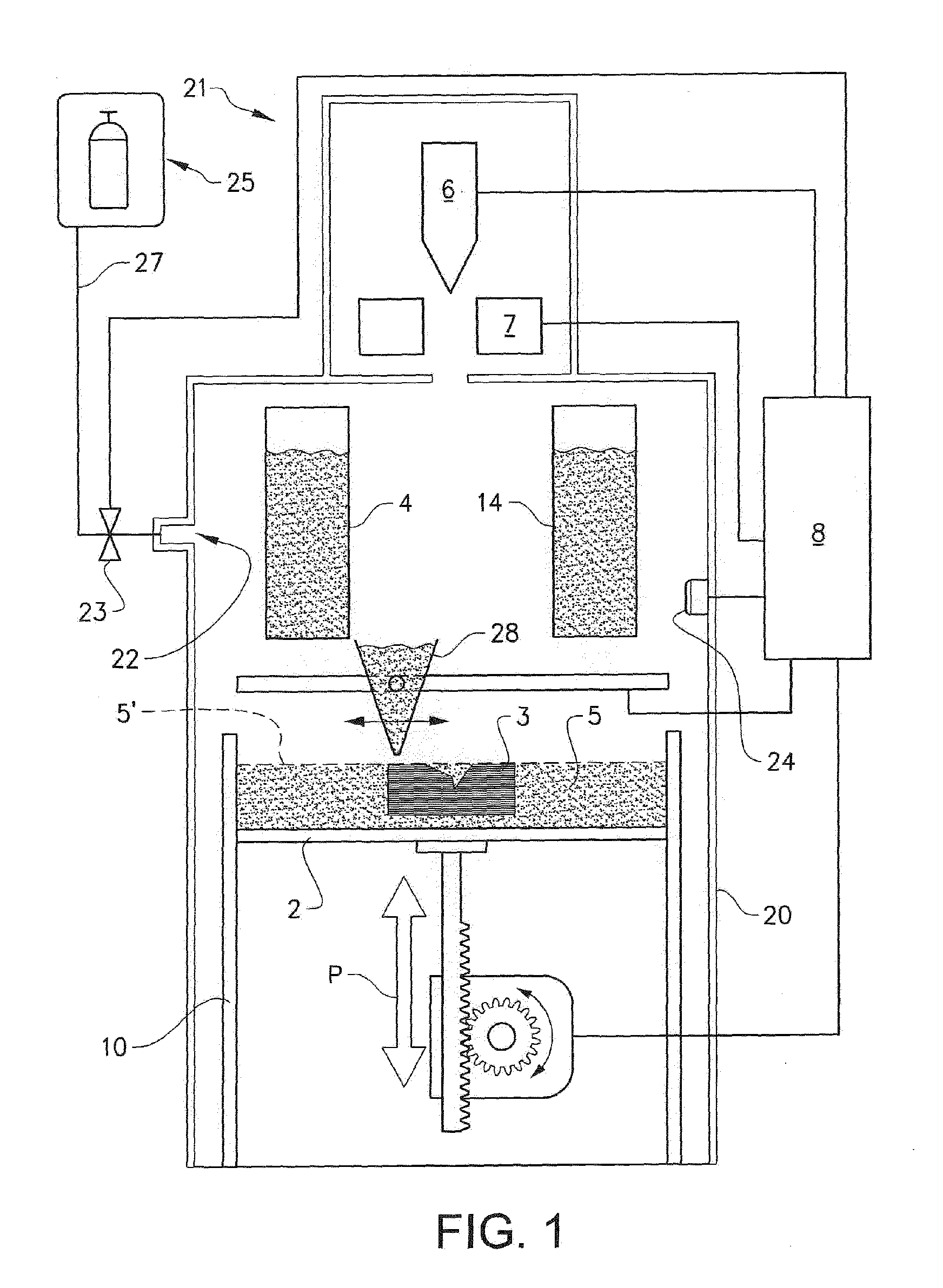
[0036] FIG. 1 depicts an embodiment of a freeform fabrication or additive manufacturing apparatus 21 in which the inventive method according to the present invention may be implemented.
[0037] The apparatus 21 comprising an electron beam gun 6; deflection coils 7; two powder hoppers 4, 14; a build platform 2; a build tank 10; a powder distributor 28; a powder bed 5; and a vacuum chamber 20.
[0038] The vacuum chamber 20 is capable of maintaining a vacuum environment by means of a vacuum system, which system may comprise a turbomolecular pump, a scroll pump, an ion pump and one or more valves which are well known to a skilled person in the art and therefore need no further explanation in this context. The vacuum system is controlled by a control unit 8.
[0039] The electron beam gun 6 is generating an electron beam which is used for melting or fusing together powder material provided on the build platform 2. At least a portion of the electron beam gun 6may be provided in the vacuum chamber 20. The control unit 8 may be used for controlling and managing the electron beam emitted from the electron beam gun 6. At least one focusing coil (not shown), at least one deflection coil 7 and an electron beam power supply (not shown) may be electrically connected to the control unit 8. In an example embodiment of the invention the electron beam gun 6 generates a focusable electron beam with an accelerating voltage of about 15-60 kV and with a beam power in the range of 3-10 Kw. The pressure in the vacuum chamber may be 10.sup.-3 mBar or lower when building the three-dimensional article by fusing the powder layer by layer with the energy beam.
[0040] The powder hoppers 4, 14 comprise the powder material to be provided on the build platform 2 in the build tank 10. The powder material may for instance be pure metals or metal alloys such as titanium, titanium alloys, aluminum, aluminum alloys, stainless steel, Co--Cr--W alloy, etc.
[0041] The powder distributor 28 is arranged to lay down a thin layer of the powder material on the build platform 2. During a work cycle the build platform 2 will be lowered successively in relation to the ray gun after each added layer of powder material. In order to make this movement possible, the build platform 2 is in one embodiment of the invention arranged movably in vertical direction, i.e., in the direction indicated by arrow P. This means that the build platform 2starts in an initial position, in which a first powder material layer of necessary thickness has been laid down. Means for lowering the build platform 2 may for instance be through a servo engine equipped with a gear, adjusting screws etc.
[0042] An energy beam may be directed over the build platform 2 causing the first powder layer to fuse in selected locations to form a first cross section of the three-dimensional article. The energy beam may be an electron beam or a particle beam. The beam is directed over the build platform 2 from instructions given by the control unit 8. In the control unit 8 instructions for how to control the beam gun for each layer of the three-dimensional article is stored.
[0043] After a first layer is finished, i.e., the fusion of powder material for making a first layer of the three-dimensional article, a second powder layer is provided on the build platform 2. The second powder layer is preferably distributed according to the same manner as the previous layer. However, there might be alternative methods in the same additive manufacturing machine for distributing powder onto the work table. For instance, a first layer may be provided by means of a first powder distributor 28, a second layer may be provided by another powder distributor. The design of the powder distributor is automatically changed according to instructions from the control unit 8. A powder distributor 28 in the form of a single rake system, i.e., where one rake is catching powder fallen down from both a left powder hopper 4 and a right powder hopper 14, the rake as such can change design.
[0044] After having distributed the second powder layer on the build platform 2, the energy beam is directed over the work table causing the second powder layer to fuse in selected locations to form a second cross section of the three-dimensional article. Fused portions in the second layer may be bonded to fused portions of the first layer. The fused portions in the first and second layer may be melted together by melting not only the powder in the uppermost layer but also remelting at least a fraction of a thickness of a layer directly below the uppermost layer.
[0045] In the case where an electron beam is used, it is necessary to consider the charge distribution that is created in the powder as the electrons hit the powder bed 5. The invention is, at least partly, based on the realization that the charge distribution density depends on the following parameters: beam current, electron velocity (which is given by the accelerating voltage), beam scanning velocity, powder material and electrical conductivity of the powder, i.e. mainly the electrical conductivity between the powder grains. The latter is in turn a function of several parameters, such as temperature, degree of sintering and powder grain size/size distribution.
[0046] Thus, for a given powder, i.e. a powder of a certain material with a certain grain size distribution, and a given accelerating voltage, it is possible, by varying the beam current (and thus the beam power) and the beam scanning velocity, to affect the charge distribution.
[0047] By varying these parameters in a controlled way, the electrical conductivity of the powder can gradually be increased by increasing the temperature of the powder. A powder that has a high temperature obtains a considerably higher conductivity which results in a lower density of the charge distribution since the charges quickly can diffuse over a large region. This effect is enhanced if the powder is allowed to be slightly sintered during the pre-heating process. When the conductivity has become sufficiently high, the powder can be fused together, i.e. melted or fully sintered, with predetermined values of the beam current and beam scanning velocity.
[0048] In a first embodiment of a method for manufacturing a porous three-dimensional article, a model is created of a non-porous three-dimensional article comprising a predetermined number of two-dimensional layers with a predetermined thickness. This non-porous model may for instance be made in a computer aided design (CAD) tool. The two-dimensional layers in the three-dimensional article may be made by slicing the three-dimensional article by a slicing tool, for instance Magics or Infinity Slicer. The non-porous three dimensional article has an outer boundary which is the same as an outer boundary of the porous final three-dimensional article, i.e., the only difference between the porous article to be manufactured and the non-porous three dimensional article lies in the porosity. It is relatively easy to make a three-dimensional design of an article which is solid in a CAD program. However, it is more difficult to make the same three-dimensional article with a randomized porosity in the same CAD program.
[0049] In a next step a model is created of a porous structure. The modelling comprising a first step of defining a three-dimensional space comprising a randomized pattern of nodes, wherein the nodes are connected together in a predetermined manner with struts.
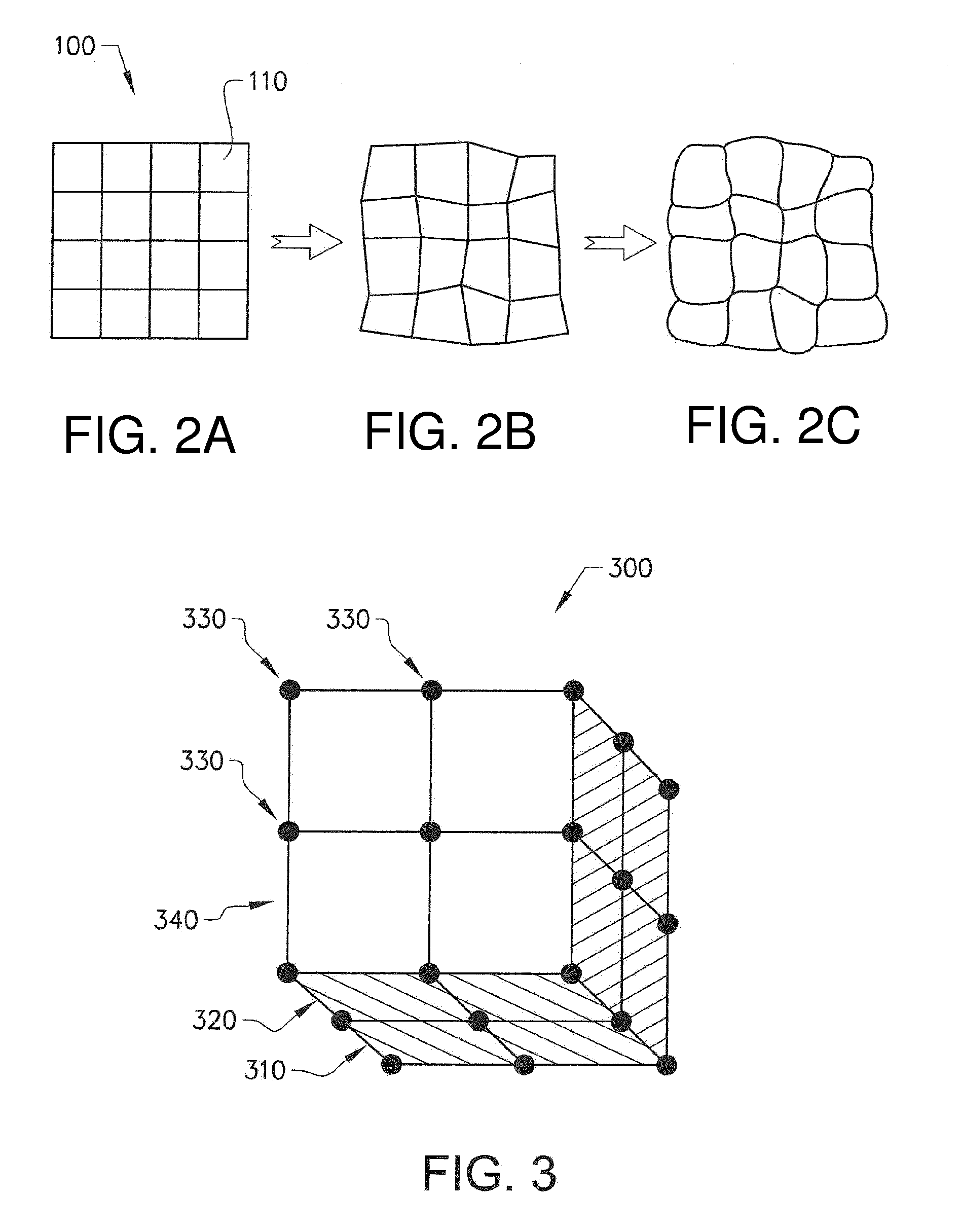
[0050] In a first example embodiment the three-dimensional space is defined by providing a regular three-dimensional pattern of nodes. The regular pattern of nodes may for instance be made of tetrahedrons, cubes or dodecahedrons, where the nodes are provided in corners and connected together in a predetermined way by struts to form regular three-dimensional structures. A distance between two nodes in the regular pattern of nodes is predetermined and can be chosen arbitrarily by an operator. FIG. 2A depicts a regular 2-dimensional square shaped network structure 100 comprising a 4.times.4 matrix of inner squares 110. FIG. 3 depicts a regular 3-dimensional cubic-shaped network structure 300comprising two layers 310, 320 of 2.times.2 matrixes of cubes. A matrix comprises a predetermined number of nodes 330 connected together in a predetermined way with a predetermined number of struts 340.
[0051] The network structure in FIG. 3 may be used as a starting point in the inventive method according to the present invention, in which an improved 3-dimensional article with porosity is to be created which is less CPU and memory consuming compared to the prior art methods.
[0052] Each and every node 330 is thereafter moved a randomized distance, which distance is less than a predetermined value and in a randomized direction. This will destroy the regularity of the original structure. In FIG. 4 the randomized distance in the randomized direction is denoted by R, where R.ltoreq.the predetermined value. The smaller the R is the smaller the destruction of the regularity of the structure will be. FIG. 2B depicts a 2-dimensional illustration of how the square original pattern may look like after moving each node the predetermined distance R in the randomized direction. FIG. 5 depicts a 3-dimensional illustration of how the cubic original pattern may look like after moving each node the predetermined distance R in the randomized direction. From the regular three dimensional structure has a completely randomized three-dimensional space been made without periodicity, which means that the randomization will look the same irrespective in which direction you will look into the three-dimensional randomized space. The hollowness, i.e., degree of empty space in the randomized space is determined by the number of nodes in the three-dimensional space, which in turn determine the number of tetrahedrons, cubes or dodecahedrons which will be stacked in the three-dimensional space. The randomization is determined by moving each node in the randomized direction but a predetermined distance R from its original position.
[0053] In a second example embodiment the three-dimensional space is defined by firstly providing a predetermined number of nodes randomly in a 3-dimensional space of a predetermined size.
[0054] Secondly a maximum number of neighbor nodes to a specific node is determined. This maximum number may be any positive integer between 1-.infin..
[0055] Thirdly a number x of closest neighbors to the specific node is skipped. X may be a random positive integer number being .gtoreq.0. Being skipped should here be interpreted as ignoring those x nodes which is/are closest to a given node.
[0056] Fourthly, each of the maximum neighbor nodes, except those nodes that might have been skipped, are connected to the specific node with a strut. Step a-d is repeated for each node in the 3-dimensional space.
[0057] In a third example embodiment the three-dimensional space is defined by firstly providing a predetermined number of nodes randomly in a 3-dimensional space of a predetermined size.
[0058] Secondly the nodes are provided in a Delauney-triangulation giving a predetermined number of Delauney-tetrahedrons. In an example embodiment the tetrahedrons are provided with smallest angles connecting the nodes, i.e., the first derivative of two struts connected together via a node is continuous.
[0059] Thirdly a Voronoi diagram is provided by for each Delauny-tetrahedron connecting the centre of the circumsphere of the Delanuney-tetrahedron with the centres of the circumspheres for all the neighbors of the Delauney-tetrahedron. The method of constructing a randomized network according to this principle is well known in the art and could be studied in for instance "Randomized incremental construction of Delaunay and Voronoi diagrams" by Leonidas J. Guibas, Donald E. Knuth and Micha Sharir.
[0060] In a second step the three-dimensional space is sliced into a predetermined number of two-dimensional layers with a predetermined thickness. The two dimensional layers could be sliced at an arbitrarily plane in the three-dimensional space. The number of two-dimensional planes building up the three-dimensional space is depending on the thickness of the two dimensional planes, the smaller the thickness of the planes the larger the number of planes it takes to build the complete three-dimensional space. FIG. 7A-7C illustrate this operation. In FIG. 7A it is depicted a three-dimensional space 700 comprising a randomized pattern of nodes connected in a predetermined way by struts 720. A two-dimensional plane 730 is grey-shaded in FIG. 7A. The two-dimensional plane has a predetermined thickness 740. In FIG. 7B the 2-dimensional plane 730 is illustrated separately from three-dimensional structure 700. In FIG. 7C it is illustrated a top view of the 2-dimensional plane which is illustrated from a side view in FIG. 7B. From FIGS. 7B and 7C it is illustrated an example 2-dimensional layer in which structures to be fused in the fusion process for forming the final 3-dimensional porous article.
[0061] In a third step one two-dimensional layer of the model of non-porous three-dimensional article is applied on one two-dimensional layer of the porous structure resulting in a porous two-dimensional layer of the article. An example embodiment of this is illustrated in FIG. 6. The porous two-dimensional layer is denoted 610. The model of the non porous two-dimensional layer is denoted 620.
[0062] The meaning of applying one two-dimensional layer of the model of non-porous three-dimensional article on one two-dimensional layer of the porous structure resulting in a porous two-dimensional layer of the article is to use a Boolean operation resulting in deletion of the porous structure outside the model of the non porous two-dimensional layer 620 and a creation of a porous structure inside the model of the non porous two-dimensional layer 620, i.e., the two-dimensional layer of the model of non-porous three-dimensional article has become a porous two-dimensional layer of the three-dimensional article denoted by 630in FIG. 6. The porous structure of the two-dimensional layer of the three-dimensional article is randomized. There is no repeatability of the randomized porous structure within the two-dimensional layer. Since a complete 3-dimensional space comprising a randomized pattern of nodes has been sliced into a predetermined number of two-dimensional layers with a predetermined thickness, there is no repeatability in the porous structure in the three-dimensional article to be produced. End points of lines may end on the outer surface of the three-dimensional article by using this method for creating a porous three-dimensional article, i.e., the porous structure of the final three-dimensional article may have an outer surface which corresponds very well with the outer surface of the model of the three-dimensional article.
[0063] In a fourth step the applying step is repeated for all two-dimensional layers of the article in order to create a complete porous 3-dimensional model of the article to be manufactured.
[0064] The porous three-dimensional article is manufactured by exposing fusible material to an energy source, so that a layer of fused material is corresponding to a porous two-dimensional layer of the article.
[0065] In another example embodiment a layer of powder material is provided on a build platform 2. The thickness of the powder material layer is adapted to the thickness of the predetermined thickness of the two-dimensional layer of the article. When deciding upon the thickness of the two-dimensional layers in the model, the thickness is corresponding to the thickness of the actual powder layer out of which the final three-dimensional article is to be made of.
[0066] The powder material may be made of metal for instance titanium, titanium alloys, Co--Cr alloys, nickel based superalloys, aluminium, aluminium alloys, etc.
[0067] The energy source may be an electron beam source, a laser source or a particle beam source.
[0068] A first derivative of at least one connection between two struts may be continuous. This is illustrated in a 2-dimensional case in FIG. 2C. This operation is optional and is used for smoothening the edges of the network structure to become more human-like.
[0069] In an example embodiment of the present invention an approximated Voronoi diagram may be used instead of the above mentioned Voronoi diagram.
[0070] In an example embodiment of the present invention a randomized pattern of point may be generated inside a volume of the porous three-dimensional object to be manufactured. This may be useful if the outer shape of the manufactured three-dimensional article need not to be identical with the model of the porous three-dimensional article. Since the randomized pattern is generated inside the volume of the three-dimensional object, it is highly likely that the outer surface in the actual manufactured article is lying inside the model of the porous three-dimensional article. The reason for this is that the very few of the randomized pattern of points may be provided exactly on the boarder of the three-dimensional article.
[0071] In an example embodiment the struts which may connect the points may be a volume element, an area element or a linear element. An area element may be flat and the linear element may be a one dimensional line.
[0072] In the fusion process such lines or points are melted as lines or points or as a 2-dimensional figure around the point or line, e.g., like small circles or ovals.
[0073] In an example embodiment a linear element may be inclined with an angle a with respect to a slicing surface, where 15.degree..ltoreq..alpha..ltoreq.165.degree.. In an example embodiment a linear element may be inclined with an angle a with respect to a slicing surface, where 10.degree..ltoreq..alpha..ltoreq.170.degree.. If a line which may connect two points lying in two different and adjacent layers is horizontal or almost horizontal, such a line may not connect the two points in the two layers after the slicing procedure and/or the manufacturing procedure.
[0074] In still another example embodiment a maximum and minimum value of the angle a may be dependent on the thickness of the slicing layer.
[0075] In an example embodiment of the present invention it is provided a method for manufacturing a porous three-dimensional article comprising the steps of: creating a model of a non-porous three-dimensional article comprising a predetermined number of two-dimensional layers with a predetermined thickness, creating a model of a porous structure comprising the steps of: defining a three-dimensional space, larger or equal to the non-porous three-dimensional space, comprising a randomized pattern of nodes, wherein the nodes are connected together in a predetermined manner with struts. Slicing the three-dimensional space into a predetermined number of two-dimensional layers with a predetermined thickness, and if necessary applying one two-dimensional layer of the model of non-porous three-dimensional article on one two-dimensional layer of the porous structure resulting in a porous two-dimensional layer of the article. Repeating the applying step for all non-porous two-dimensional layers of the article, manufacturing the porous three-dimensional article by exposing fusible material to an energy source, so that a layer of fused material is corresponding to a porous two-dimensional layer of the article.
[0076] In still another example embodiment of the present invention the struts may either be described by volume, area or line elements or by any combination of these elements.
[0077] In still another example embodiment of the present invention the porous two-dimensional layers of the article may be described by either the 2D polygon data created from slicing the volume elements or of 2D line data created from slicing the area elements or of 2D point data created from slicing line elements or by any combination of these three sets of data.
[0078] In yet another example embodiment of the present invention the 2D line data and 2D point data in the porous two-dimensional layers of the article may be expanded to a predetermined 2D polygon data located at a predetermined position relative to the 2D line data or to the 2D point data.
[0079] The invention is not limited to the above-described embodiments and many modifications are possible within the scope of the following claims. Such modifications may, for example, involve using a different source of ray gun than the exemplified electron beam such as laser beam. Other materials than metallic powder may be used such as powder of polymers or powder of ceramics.
[0080] The invention is not limited to the above-described embodiments and many modifications are possible within the scope of the following claims.
* * * * *
D00000
D00001
D00002
D00003
D00004
XML
uspto.report is an independent third-party trademark research tool that is not affiliated, endorsed, or sponsored by the United States Patent and Trademark Office (USPTO) or any other governmental organization. The information provided by uspto.report is based on publicly available data at the time of writing and is intended for informational purposes only.
While we strive to provide accurate and up-to-date information, we do not guarantee the accuracy, completeness, reliability, or suitability of the information displayed on this site. The use of this site is at your own risk. Any reliance you place on such information is therefore strictly at your own risk.
All official trademark data, including owner information, should be verified by visiting the official USPTO website at www.uspto.gov. This site is not intended to replace professional legal advice and should not be used as a substitute for consulting with a legal professional who is knowledgeable about trademark law.