Thermostatic Apparatus and Analytical Apparatus Including the Same
Morisaki; Atsuki ; et al.
U.S. patent application number 16/106935 was filed with the patent office on 2019-02-28 for thermostatic apparatus and analytical apparatus including the same. This patent application is currently assigned to Hitachi High-Tech Science Corporation. The applicant listed for this patent is Hitachi High-Tech Science Corporation. Invention is credited to Masahito Ito, Atsuki Morisaki, Koji Yamamoto.
| Application Number | 20190060908 16/106935 |
| Document ID | / |
| Family ID | 65321305 |
| Filed Date | 2019-02-28 |


View All Diagrams
| United States Patent Application | 20190060908 |
| Kind Code | A1 |
| Morisaki; Atsuki ; et al. | February 28, 2019 |
Thermostatic Apparatus and Analytical Apparatus Including the Same
Abstract
A thermostatic apparatus thermostatically holds a sample container holding a sample. The thermostatic apparatus includes a sample rack which accommodates and holds a plurality of the sample containers and is attachable to and detachable from the thermostatic apparatus; and a heat conduction member which is controlled to a constant temperature and transfers heat to the sample container, in which an opening portion is formed in the sample rack, and when the sample rack is mounted on the thermostatic apparatus, a contact portion forming one part of the heat conduction member directly contacts the sample container by passing through the opening portion, or directly contacts the sample container protruding from the opening portion.
| Inventors: | Morisaki; Atsuki; (Tokyo, JP) ; Yamamoto; Koji; (Tokyo, JP) ; Ito; Masahito; (Tokyo, JP) | ||||||||||
| Applicant: |
|
||||||||||
|---|---|---|---|---|---|---|---|---|---|---|---|
| Assignee: | Hitachi High-Tech Science
Corporation Tokyo JP |
||||||||||
| Family ID: | 65321305 | ||||||||||
| Appl. No.: | 16/106935 | ||||||||||
| Filed: | August 21, 2018 |
| Current U.S. Class: | 1/1 |
| Current CPC Class: | G01N 1/30 20130101; B01L 2300/0858 20130101; G01N 2035/00356 20130101; G01N 35/00 20130101; G01N 35/00584 20130101; B01L 2300/1805 20130101; B01L 2300/041 20130101; B01L 2200/02 20130101; B01L 7/00 20130101; B01L 2400/0475 20130101 |
| International Class: | B01L 7/00 20060101 B01L007/00 |
Foreign Application Data
| Date | Code | Application Number |
|---|---|---|
| Aug 25, 2017 | JP | 2017-161961 |
Claims
1. A thermostatic apparatus configured to thermostatically hold a sample container, the sample container being configured to hold a sample, the thermostatic apparatus comprising: a sample rack configured to accommodate and hold a plurality of the sample containers, the sample rack being attachable to and detachable from the thermostatic apparatus, the sample rack comprising an opening portion; and a heat conduction member configured to be controlled to a constant temperature and to transfer heat to the sample container, wherein the heat conduction member comprises a contact portion configured to directly contact the sample container when the sample rack is mounted on the thermostatic apparatus, the contact portion directly contacting the sample container through the opening portion or directly contacting the sample container that protrudes from the opening portion.
2. The thermostatic apparatus according to claim 1, wherein the opening portion is formed in a bottom surface of the sample rack, and wherein the contact portion directly contacts a bottom surface of the sample container.
3. The thermostatic apparatus according to claim 1, wherein the heat conduction member has an inner bottom surface that is located further downward than the sample rack, and wherein the inner bottom surface of the heat conduction member forms a flow path, the flow path descending in one direction and configured to discharge condensation water generated during cooling of the sample container to the outside.
4. The thermostatic apparatus according to claim 1, wherein the heat conduction member further comprises a groove extending in a first direction, and wherein an inner bottom surface of the groove forms a flow path, the flow path descending from a first end of the groove toward a second end of the groove and being configured to discharge condensation water generated during cooling of the sample container to the outside through the second end.
5. The thermostatic apparatus according to claim 4, wherein the first end of the groove is not communicated with a first side surface of the sample rack, and the second end of the groove is communicated with a second side surface of the sample rack.
6. The thermostatic apparatus according to claim 4, wherein the sample rack comprises a stopper extending in the first direction at a lower side of the opening portion, and wherein the stopper is accommodated in the groove when the sample rack is attached to the heat conduction member.
7. The thermostatic apparatus according to claim 5, wherein a depth of the groove at the second end is greater than a projection height of the stopper from a back surface of the sample rack.
8. The thermostatic apparatus according to claim 1, wherein the sample rack is attachable to and detachable from the thermostatic apparatus in a first direction, and wherein the heat conduction member further comprises a groove extending in the first direction.
9. The thermostatic apparatus according to claim 8, wherein the sample rack comprises a stopper extending in the first direction at a lower side of the opening portion, and wherein the stopper is accommodated in the groove when the sample rack is mounted on the heat conduction member.
10. The thermostatic apparatus according to claim 1, wherein the opening portion comprises: a first opening opened on a front surface of the sample rack and configured to accommodate and hold the sample container; and a second opening extending in a first direction and opened on a side surface of the sample rack, the second opening being communicated with the first opening.
11. The thermostatic apparatus according to claim 10, wherein a plurality of the second openings are disposed on the side surface of the sample rack along a second direction that is substantially perpendicular to the first direction.
12. The thermostatic apparatus according to claim 1, wherein the sample rack is attachable to and detachable from the heat conduction member in a first direction, and wherein at least one of the sample rack and the heat conduction member further comprises a plurality of openings opened on a side surface thereof along a second direction, the second direction being substantially perpendicular to the first direction.
13. An analytical apparatus comprising: the thermostatic apparatus according to claim 1.
14. The analytical apparatus according to claim 13, further comprising: a mobile phase container accommodating a mobile phase; an auto-sampler; a pump configured to feed the mobile phase from the mobile phase container to the auto-sampler; a separation column; a column oven configured to accommodate the separation column; a detector; a waste liquid container; and a computer, wherein the thermostatic apparatus is attached to the auto-sampler.
Description
[0001] This application claims priority from Japanese Patent Application No. 2017-161961 filed on Aug. 25, 2017, the entire subject-matter of which is incorporated herein by reference.
TECHNICAL FIELD
[0002] The disclosure relates to a thermostatic apparatus and an analytical apparatus including the same.
BACKGROUND ART
[0003] In a liquid chromatography apparatus, a plurality of sample containers for holding samples are accommodated in a sample rack, each sample rack is mounted to an auto-sampler, and the samples in the sample containers are sucked by a suction needle of the auto-sampler and are introduced into the liquid chromatography apparatus so as to perform an analysis.
[0004] Here, in order to prevent decomposition of the samples, volatilization of solvents, in which the samples are dissolved, or the like, the sample containers may be cooled. There has been developed a technology for cooling a sample container (sample) by making a cooling part contact a bottom surface of a sample rack which is formed of a metal excellent in heat conduction (refer to WO 2014/155674 A1).
[0005] In a case where the cooling part is brought into contact with the bottom surface of the sample rack, cooling is performed by transferring (taking) heat from the sample rack to the cooling portion mainly by heat conduction.
[0006] However, since surfaces of the sample rack and the cooling part are not completely plane surfaces and have fine unevenness, instead, an air layer exists between the two surfaces, and heat conduction is inhibited. In addition, since the sample rack is generally large to accommodate a large number of sample containers, the heat capacity thereof is also large, and therefore it takes time to cool the sample rack. Further, since an upper surface and a side surface of the sample rack are generally exposed to the outside, the sample rack is warmed up by outside air at these parts, so that cooling efficiency decreases.
[0007] Meanwhile, in order to shorten cooling time of the sample rack, it is preferable to improve cooling capability of the cooling part, but a size and power consumption of the apparatus are increased.
[0008] In addition, condensation water may be generated on surfaces of the sample containers when the sample containers are cooled. However, it is difficult to discharge the condensation water from the sample rack, so that moisture from the condensation water may affect analytical accuracy. Therefore, the related-art technology of WO 2014/155674 A1 is provided with a device, which is separated from the cooling part, and which dehumidifies air of measured atmosphere. However, it increases the cost.
SUMMARY
[0009] Illustrative aspects of the disclosure provide a thermostatic apparatus, which can thermostatically hold the sample container while suppressing increase in size and power consumption of the apparatus, and which can discharge the condensation water during cooling easily, and provide an analytical apparatus including the thermostatic apparatus.
[0010] According to one illustrative aspect of the disclosure, there may be provided a thermostatic apparatus configured to thermostatically hold a sample container, the sample container being configured to hold a sample, the thermostatic apparatus comprising: a sample rack configured to accommodate and hold a plurality of the sample containers, the sample rack being attachable to and detachable from the thermostatic apparatus, the sample rack comprising an opening portion; and a heat conduction member configured to be controlled to a constant temperature and to transfer heat to the sample container, wherein the heat conduction member comprises a contact portion configured to directly contact the sample container when the sample rack is mounted on the thermostatic apparatus, the contact portion directly contacting the sample container through the opening portion or directly contacting the sample container that protrudes from the opening portion.
[0011] According to the thermostatic apparatus, when the sample rack is mounted on the thermostatic apparatus, the contact portion directly contacts the sample containers via the opening portion or directly contacts the sample containers protruding from the opening portion. Therefore, heat can be effectively transferred to (or taken from) the sample containers, and it becomes possible to thermostatically hold the sample containers rapidly while suppressing increase in size and power consumption of the apparatus, compared with a case where the heat conduction member is brought into contact with the sample rack and heat is transferred to (or taken from) the sample containers indirectly.
[0012] In addition, since the opening portion is formed in the sample rack, even if condensation water is generated on the surfaces of the sample containers when the sample containers are cooled, the condensation water is easily discharged through the opening portion.
[0013] In the thermostatic apparatus of the disclosure, the opening portion may be formed in a bottom surface of the sample rack, and the contact portion may directly contact a bottom surface of the sample container.
[0014] According to the thermostatic apparatus, since the contact portion directly contacts the bottom surface of the sample container, heat can be more effectively transferred to (or taken from) the sample container.
[0015] In the thermostatic apparatus of the disclosure, the heat conduction member may have an inner bottom surface that is located further downward than the sample rack, and the inner bottom surface of the heat conduction member may form a flow path, the flow path descending in one direction and configured to discharge condensation water generated during cooling of the sample container to the outside.
[0016] According to the thermostatic apparatus, the condensation water generated during cooling of the sample containers falls from the opening portion to the bottom surface of the heat conduction member, and flows along the inclination so as to be discharged to the outside, so that the condensation water can be discharged more rapidly to the outside.
[0017] In the thermostatic apparatus of the disclosure, the heat conduction member may further comprise a groove extending in a first direction, and an inner bottom surface of the groove may form a flow path, the flow path descending from a first end of the groove toward a second end of the groove and being configured to discharge condensation water generated during cooling of the sample container to the outside through the second end.
[0018] In the thermostatic apparatus of the disclosure, the first end of the groove may not be communicated with a first side surface of the sample rack, and the second end of the groove may be communicated with a second side surface of the sample rack.
[0019] In the thermostatic apparatus of the disclosure, the sample rack may comprise a stopper extending in the first direction at a lower side of the opening portion, and the stopper may be accommodated in the groove when the sample rack is attached to the heat conduction member.
[0020] In the thermostatic apparatus of the disclosure, a depth of the groove at the second end may be greater than a projection height of the stopper from a back surface of the sample rack.
[0021] In the thermostatic apparatus of the disclosure, the sample rack may be attachable to and detachable from the thermostatic apparatus in a first direction, and the heat conduction member may further comprise a groove extending in the first direction.
[0022] In the thermostatic apparatus of the disclosure, the sample rack may comprise a stopper extending in the first direction at a lower side of the opening portion, and the stopper may be accommodated in the groove when the sample rack is mounted on the heat conduction member.
[0023] In the thermostatic apparatus of the disclosure, the opening portion may comprise: a first opening opened on a front surface of the sample rack and configured to accommodate and hold the sample container; and a second opening extending in a first direction and opened on a side surface of the sample rack, the second opening being communicated with the first opening.
[0024] In the thermostatic apparatus of the disclosure, a plurality of the second openings may be disposed on the side surface of the sample rack along a second direction that is substantially perpendicular to the first direction.
[0025] In the thermostatic apparatus of the disclosure, the sample rack may be attachable to and detachable from the heat conduction member in a first direction, and at least one of the sample rack and the heat conduction member may further comprise a plurality of openings opened on a side surface thereof along a second direction, the second direction being substantially perpendicular to the first direction.
[0026] The disclosure may provide an analytical apparatus including the above-described thermostatic apparatus.
[0027] The analytical apparatus of the disclosure may further comprise: a mobile phase container accommodating a mobile phase; an auto-sampler; a pump configured to feed the mobile phase from the mobile phase container to the auto-sampler; a separation column; a column oven configured to accommodate the separation column; a detector; a waste liquid container; and a computer, wherein the thermostatic apparatus is attached to the auto-sampler.
[0028] According to the disclosure, it is possible to suppress the increase in size and power consumption of the thermostatic apparatus and to thermostatically hold the sample container, and the condensation water can be easily discharged during cooling.
BRIEF DESCRIPTION OF DRAWINGS
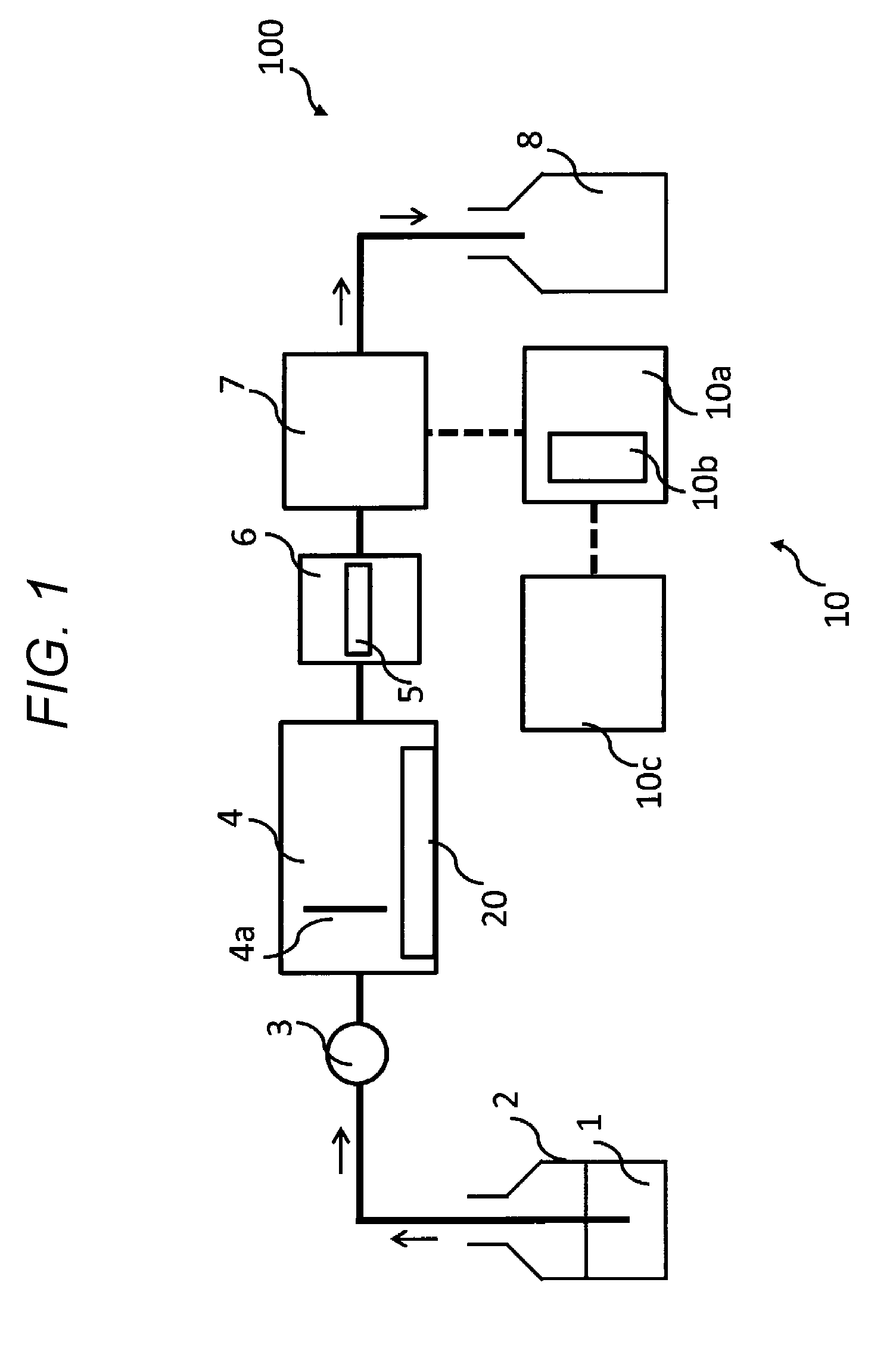
[0029] FIG. 1 is a diagram showing a configuration of a thermostatic apparatus and an analytical apparatus including the same according to an embodiment of the disclosure;
[0030] FIG. 2 is a view showing a configuration of the thermostatic apparatus;
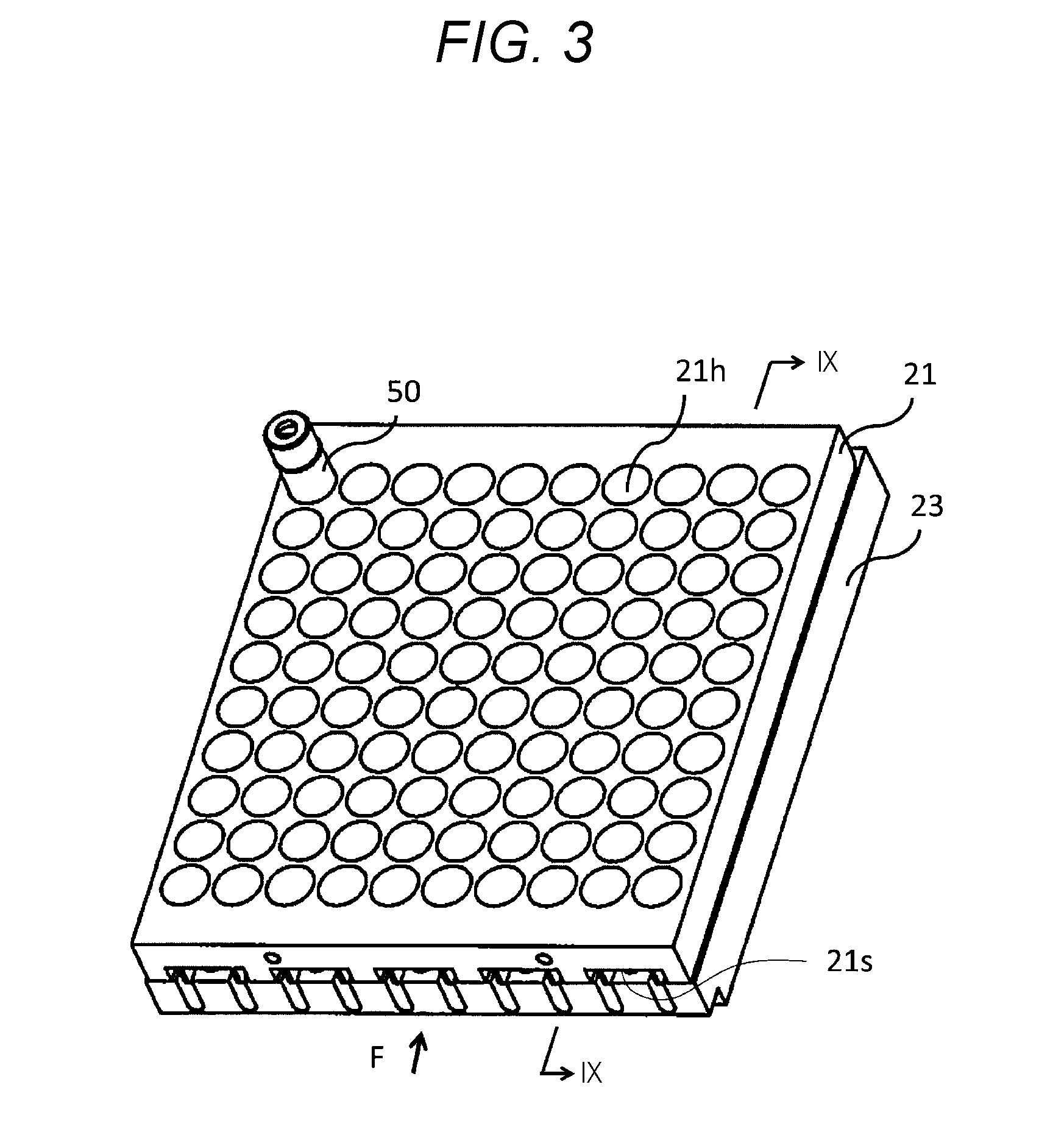
[0031] FIG. 3 is an enlarged perspective view of the thermostatic apparatus;
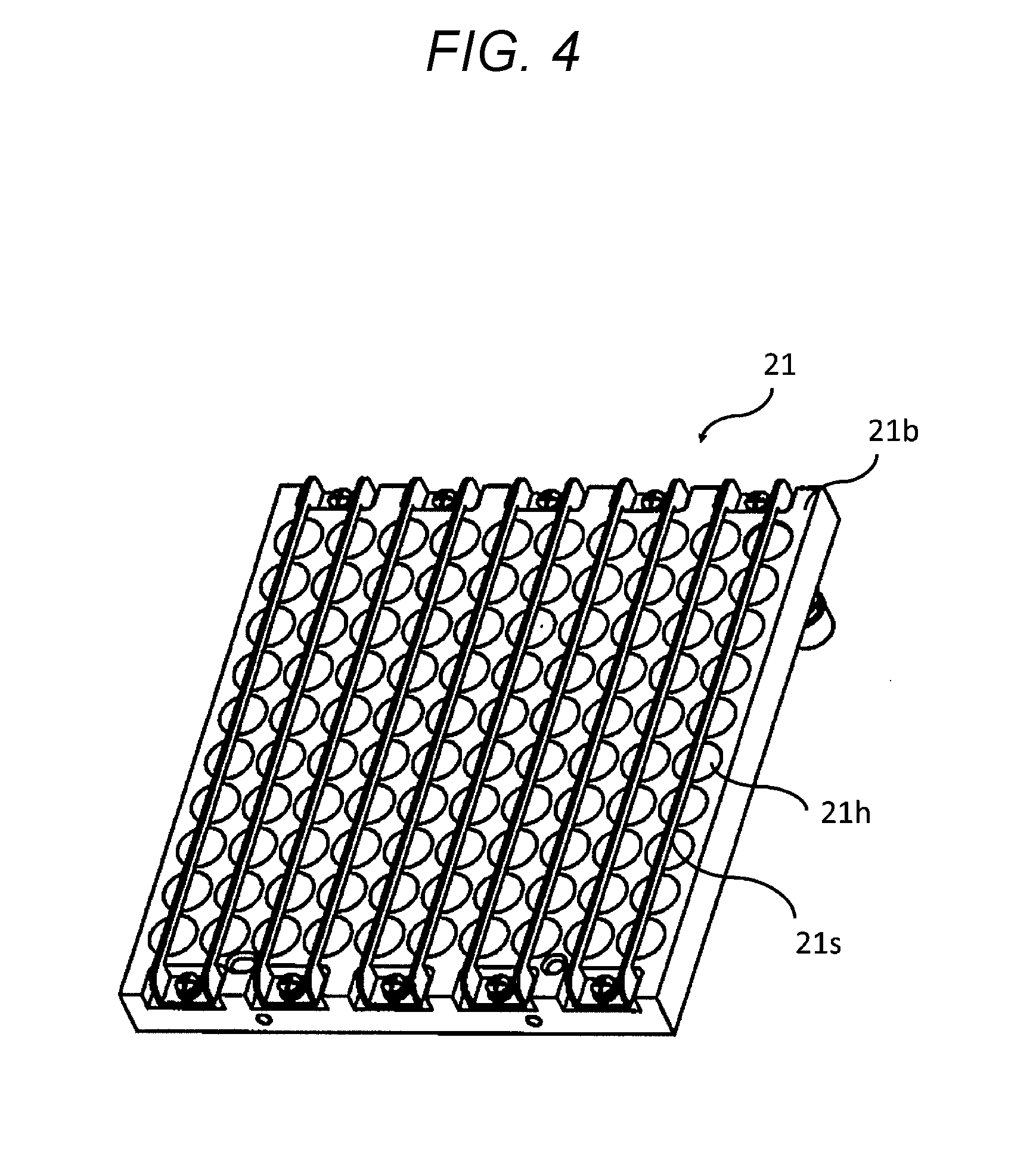
[0032] FIG. 4 is a perspective view of a back surface of a sample rack;
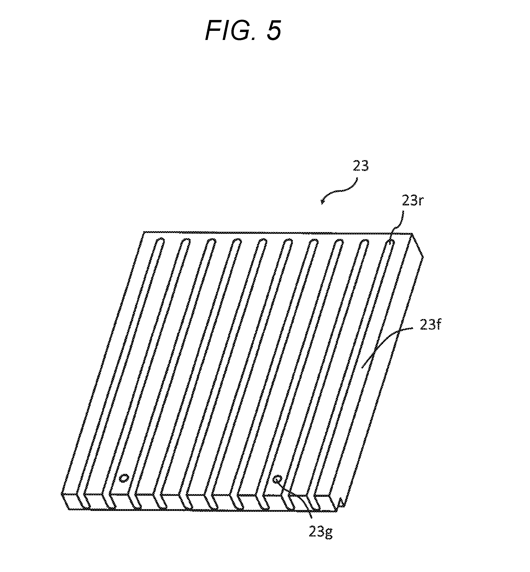
[0033] FIG. 5 is a perspective view of a heat conduction member;
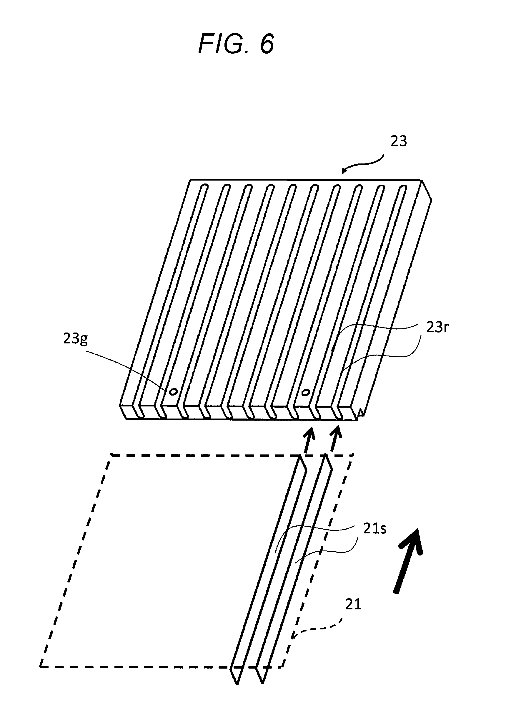
[0034] FIG. 6 is a view showing a state where the sample rack is slid in a horizontal direction to be mounted to the heat conduction member;
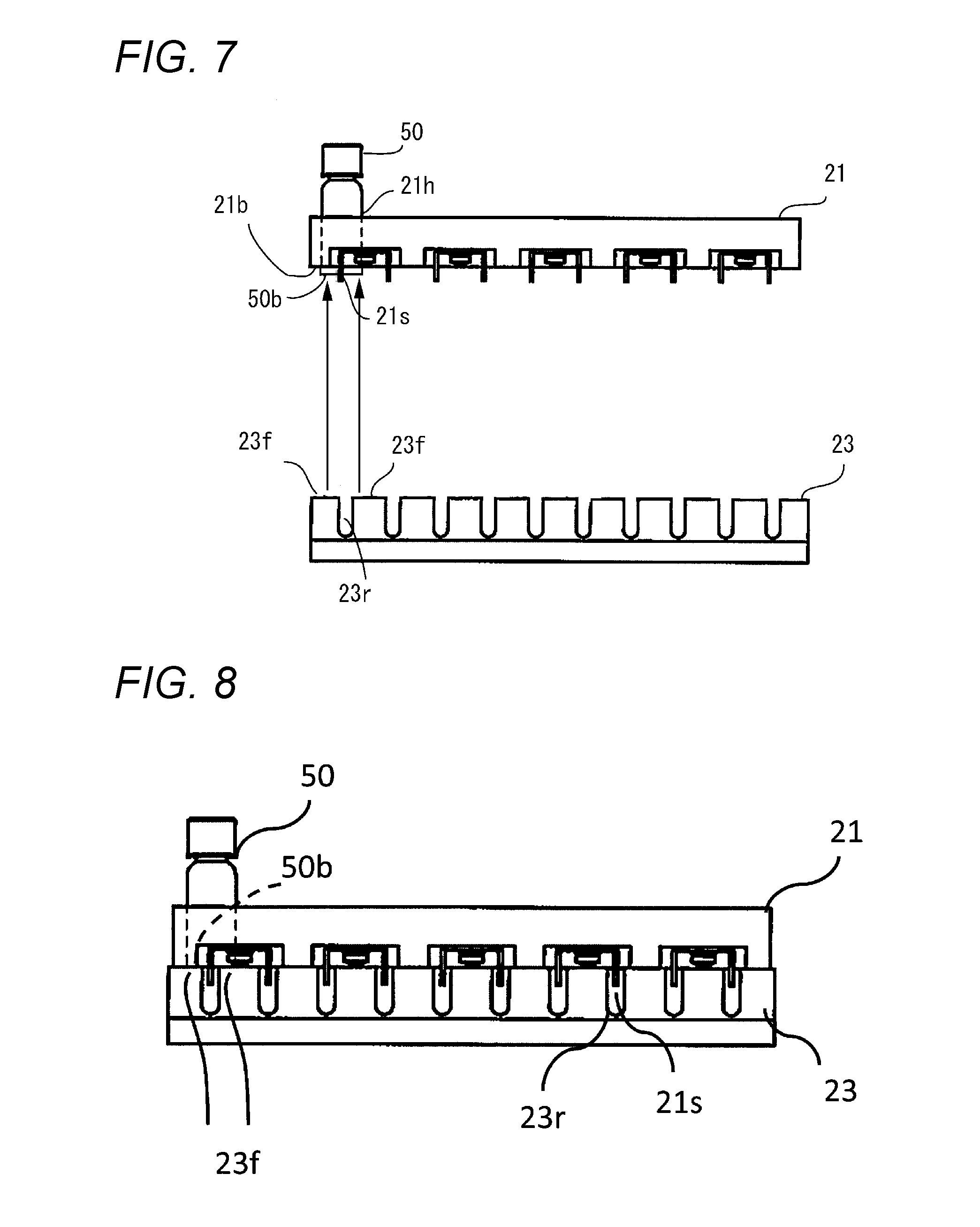
[0035] FIG. 7 is a view showing a state where a bottom surface of a sample container protrudes further downward than the sample rack;
[0036] FIG. 8 is a view showing a state where the heat conduction member directly contacts the sample container when the sample rack is mounted on the heat conduction member;
[0037] FIG. 9 is a cross sectional view taken along a line IX-IX in FIG. 3;
[0038] FIG. 10 is a perspective view of a sample rack according to a modification of the disclosure;
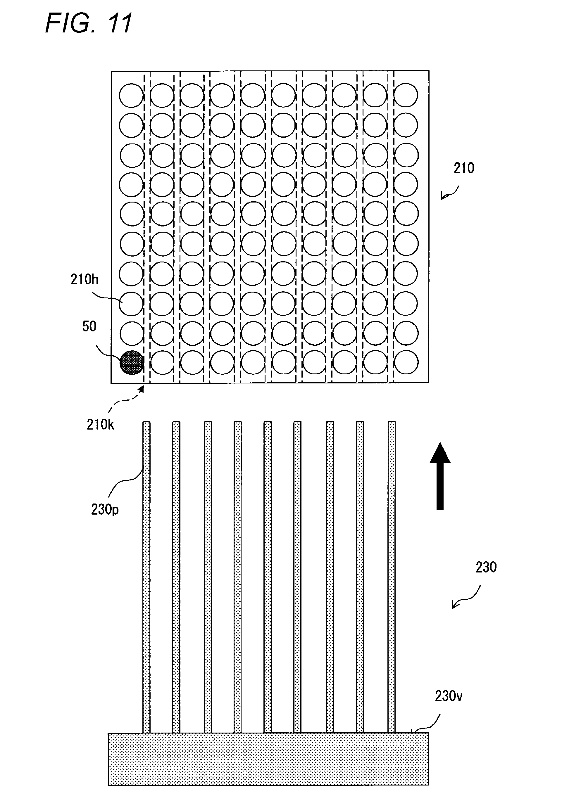
[0039] FIG. 11 is a plan view of the thermostatic apparatus including the sample rack in FIG. 10;
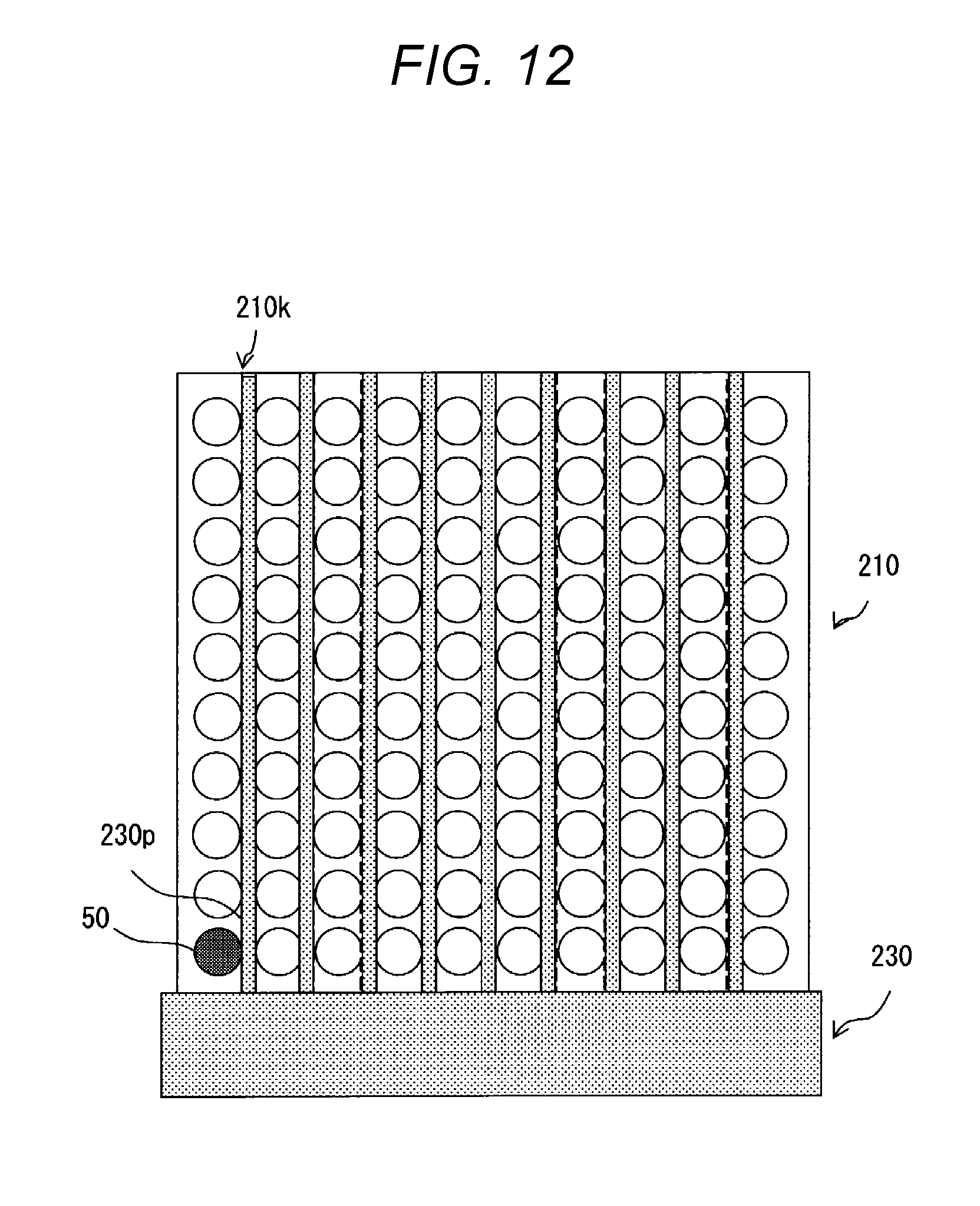
[0040] FIG. 12 is a view showing a state where the sample rack in FIG. 11 is mounted on the heat conduction member;
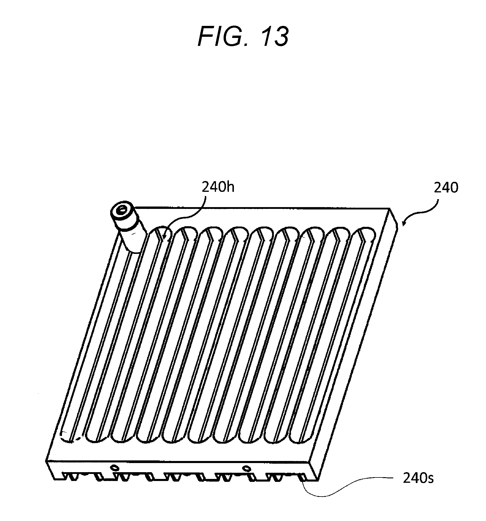
[0041] FIG. 13 is a perspective view of a sample rack according to another modification of the disclosure; and
[0042] FIG. 14 is a perspective view of a sample rack according to still another modification of the disclosure.
DETAILED DESCRIPTION
[0043] Hereinafter, embodiments of the disclosure will be described with reference to the drawings.
[0044] FIG. 1 is a view showing a configuration of a liquid chromatography apparatus (analytical apparatus) 100 according to an embodiment of the disclosure, FIG. 2 is a view showing a configuration of a thermostatic apparatus 20, and FIG. 3 is an enlarged perspective view of the thermostatic apparatus 20.
[0045] The liquid chromatography apparatus 100 includes a mobile phase container 2 accommodating a mobile phase 1 (solvent), an auto-sampler 4, a pump 3 for feeding the mobile phase 1 from the mobile phase container 2 to the auto-sampler 4, the thermostatic apparatus 20 attached to the auto-sampler 4, a separation column 5, a column oven 6 for accommodating the separation column 5, a detector 7, a waste liquid container 8, a computer 10 or the like. The computer 10 includes a processing unit (CPU) 10a, a data holding unit 10b including a hard disk or the like, and a display unit 10c.
[0046] A suction needle (syringe) 4a is provided at the auto-sampler 4. The suction needle 4a sucks a sample from a sample container 50 (see FIG. 2) that is arranged at the thermostatic apparatus 20 and feeds the sample into the separation column 5 together with the mobile phase 1. The sample fed into the separation column 5 is detected by the detector 7, and a detection signal (chromatogram) is analyzed and displayed or the like by the computer 10.
[0047] As shown in FIGS. 2 and 3, the thermostatic apparatus 20 includes a sample rack 21 which accommodates a plurality of sample containers 50 and is attachable to/detachable from the auto-sampler 4, a heat conduction member 23 which is attached to the auto-sampler 4 and a thermostatic unit 25 which controls the heat conduction member 23 to a constant temperature.
[0048] In the present embodiment, the thermostatic unit 25 includes a cooling member such as a Peltier element, a fan for cooling a heating generation portion of the Peltier element, a control circuit or the like. A cooling surface of the Peltier element thermally contacts a lower surface of the heat conduction member 23, and heat of the heat conduction member 23 is taken, so that cooling is performed at a constant temperature (for example, 4.degree. C.).
[0049] The sample container 50 includes a cylindrical glass bottle and a lid. The sample rack 21 has a substantially box shape. The sample rack 31 is provided with a plurality of through holes 21h having a diameter slightly larger than that of each sample container 50 and being opened upward and downward, and the sample containers 50 are inserted into each through hole 21h from above. Incidentally, a plurality of stoppers 21s (see FIG. 4) for preventing the sample containers 50 from falling off are provided at a lower side of the through holes 21h.
[0050] The through hole 21h is one example of an opening portion.
[0051] As shown in FIG. 4, the stopper 21s is a strip-shaped member which is separated from a back surface 21b of the sample rack 21 and overlaps the through hole 21h when viewed from a vertical direction. In the present embodiment, the stopper 21s is arranged to extend in one direction of the sample rack 21 and to overlap centers of each row of the through holes 21h along the above-described one direction. Further, as shown in FIG. 7 which is to be described later, a bottom surface of the sample container 50 which falls to a lower side of the through hole 21h is supported by the stopper 21s, and therefore the bottom surface of the sample container 50 is exposed.
[0052] Incidentally, the stopper 21s is formed by bending a stainless plate cut out in a rectangle shape into a U shape such that sides in a longitudinal direction are parallel, and the stopper 21s is attached by fastening both ends in the longitudinal direction of the stopper 21s onto the back surface 21b of the sample rack 21 with screws. Further, the stopper 21s is separated from the back surface 21b of the sample rack 21 and protrudes further than the back surface 21b.
[0053] Further, the sample rack 21 is mounted on the heat conduction member 23 while being slid in the horizontal direction (see arrow from front to back in FIG. 2 and arrow F in FIG. 3), and the heat conduction member 23 and the sample rack 21 are brought into thermal contact with each other.
[0054] For this reason, the heat conduction member 23 and the sample rack 21 are formed of aluminum with excellent heat conduction.
[0055] Incidentally, when sucking the sample from the sample container 50 with the suction needle (syringe) 4a, a syringe switching valve 4b and an injection switching valve 4c are switched appropriately.
[0056] On the other hand, as shown in FIG. 5, a plurality of grooves 23r extending in one direction and positioning holes 23g are provided on an upper surface 23f of the heat conduction member 23. The extending direction of the groove 23r and the number thereof are the same with the stopper 21s.
[0057] Therefore, as shown in FIG. 6, when the sample rack 21 is mounted on the heat conduction member 23 while being slid in the horizontal direction, each stopper 21s is accommodated in respective groove 23r. Further, after the sample rack 21 is mounted, the sample rack 21 and the heat conduction member 23 are positioned by inserting positioning pins (not shown) of the sample rack 21 into the positioning holes 23g.
[0058] Next, a contact state between the heat conduction member 23 and the sample container 50, which is a characterizing part of the disclosure, will be described with reference to FIGS. 7 to 9.
[0059] As shown in FIG. 7, when the sample container 50 is inserted into the through hole 21h of the sample rack 21, a bottom surface 50b of the sample container 50 which falls to a lower side of the through hole 21h is supported by an upper surface of the stopper 21s. Further, the bottom surface 50b of the sample container 50 protrudes slightly further downward than the back surface 21b of the sample rack 21.
[0060] At this time, at the mounting position of the sample rack 21, the groove 23r of the heat conduction member 23 faces the stopper 21s, and adjacent upper surfaces 23f on both sides of the groove 23r face the bottom surface 50b of the sample container 50 (see arrow in the FIG. 7).
[0061] Therefore, when the sample rack 21 is mounted on the heat conduction member 23 while being slid in the horizontal direction as shown in FIG. 6, each stopper 21s is accommodated in respective groove 23r as shown in FIG. 8, and the adjacent upper surfaces 23f on both sides of the groove 23r directly contact the bottom surface 50b while slightly pushing up the bottom surface 50b of the sample container 50.
[0062] Thus, compared with a case where the heat conduction member 23 contacts the sample rack 21 and the heat is indirectly transferred to (or taken from) the sample container 50, the heat can be effectively transferred to (or taken from) the sample container 50, and it becomes possible to thermostatically hold the sample container 50 quickly while suppressing the increase in size and energy consumption of the apparatus.
[0063] In the sample rack 21, each through hole 21h is formed for respective sample container 50. Thus, even if condensation water is generated on a surface of the sample container 50 when the sample container 50 is cooled, the condensation water is easy to be discharged through the through hole 21h. As a result, it is possible to suppress the influence of moisture from the condensation water on analysis accuracy.
[0064] Incidentally, the upper surface 23f of the heat conduction member 23 is one example of a contact portion.
[0065] As shown in FIG. 9, in the present embodiment, a bottom surface 23c of each groove 23r of the heat conduction member 23 is located further downward than the sample rack 21 and descends in one direction (e.g., extending direction of each stopper 21s, toward right in FIG. 9). Therefore, the condensation water generated during the cooling of the sample container 50 drops from the though hole 21h to the bottom surface 23c, flows along the inclination thereof toward the right side in FIG. 9 and is discharged to the outside. That is, the bottom surface 23c forms a discharge flow path of the condensation water.
[0066] Thus, the condensation water can be discharged to the outside more quickly.
[0067] The disclosure is not limited to the above-described embodiment, and it goes without saying that it extends to various modifications and equivalents included in the spirit and scope of the disclosure.
[0068] For example, as shown in FIG. 10, it may be configured to form a plurality of slits 210k extending in one direction (from front to back in FIG. 10) in a side surface of a sample rack 210 and insert protruding portions 230p of a heat conduction member 230 shown in FIG. 11 into the slits 210k, and thus the sample container 50 may be held thermostatically.
[0069] Specifically, as shown in FIG. 11, the slit 210k is separated from through holes 210h (same as the through holes 21h in FIG. 3) for accommodating each sample container 50. The slit 210k penetrates through the sample rack 210 between the through holes 210h which are adjacent in a direction perpendicular to the above-described one direction so as to form rectangular through holes extending in the above-described one direction. The slit 210k is in communication with the through hole 210h, and a part of side walls of the through holes 210h are opened and is connected to the slit 210k. In FIG. 11, nine slits 210k in total are provided.
[0070] On the other hand, nine protruding portions 230p of the heat conduction member 230 are provided in a comb tooth shape to face each slit 210k, and a base portion of the protruding portions 230p is connected to a base 230v integrally. Further, the base 230v thermally contacts a thermostatic unit (not shown) and is held thermostatically, so that the heat of the thermostatic unit is transferred to each slit 210k.
[0071] Further, as shown in FIG. 12, when each protruding portion 230p is inserted into respective slit 210k while being slid in the horizontal direction, each protruding portion 230p directly contacts a side wall of sample container 50 with passing through the through hole 210h that is in communication with each slit 210k.
[0072] In this way, compared with a case where the heat conduction member 230 contacts with the sample rack 210 and heat is indirectly transferred to (or taken from) the sample container 50, the heat can be effectively transferred to (taken from) the sample container 50. Further, the condensation water is easy to be discharged from the slit 210k.
[0073] Incidentally, the slit 210k and the through hole 210h are one example of the opening portion, and the protruding portion 230p is one example of the contact portion.
[0074] As described above, the case of the sample rack 21 in FIGS. 3 and 4 is an aspect in which the bottom surface of the sample container 50 protrudes from the opening portion (the through hole 21h) and the contact portion (the upper surface 23f) directly contacts the protruding portion.
[0075] On the other hand, the case of the sample rack 210 in FIGS. 10 and 11 is an aspect in which the sample container 50 does not protrude from the opening portion (the slit 210k and the through hole 210h), and the contact portion (protruding portion 230p) directly contacts the sample container 50 through the opening portion (with entering into the opening portion).
[0076] Incidentally, for example, a case where the opening portion (the through hole 21h) and the bottom surface of the sample container 50 in the sample rack 21 are aligned with each other, is regarded as the aspect in which the contact portion (the upper surface 23f) directly contacts the bottom surface of the sample container 50 through the opening portion.
[0077] Further, the "opening portion" may not be formed for each sample container 50. For example, as shown in FIG. 13, a plurality of oval-shaped (e.g., rounded rectangular-shaped) through holes 240h extending in one direction of a sample rack 240 may be provided, and a plurality of the sample containers 50 may be accommodated and held along the longitudinal direction of one through hole 240h by configuring the through hole 240h such that a short diameter thereof is slightly larger than a diameter of the sample container 50 and a long diameter thereof is slightly larger than the multiple of the diameter of the sample container 50.
[0078] Incidentally, stoppers 240s which are the same as the stoppers 21s in FIG. 4 are attached to the sample rack 240 to hold the bottom surfaces of the sample containers 50.
[0079] Similarly, for example, as shown in FIG. 14, only an outer periphery of a sample rack 250 remains in a frame shape and one large rectangular through hole 250h (the opening portion) is provided inside this outer periphery; further, a plurality of wires 250w are arranged in a grid pattern with intervals in the vertical and horizontal directions on the through hole 250h, so that each sample container 50 may be accommodated right in each grid. Thus, a plurality of sample containers 50 can be accommodated and held by being supported by the wires 250w in one through hole 250h.
[0080] Incidentally, stoppers 250s which are the same as the stoppers 21s in FIG. 4 are attached to the sample rack 250 to hold the bottom surfaces of the sample containers 50.
[0081] The sample rack "holding the sample container" means that the sample container accommodated in the sample rack does not fall off and the sample rack can be moved together with the sample container. For example, in the case of FIG. 4, the opening portion 21h and the stopper 21s have the function of "holding the sample container".
[0082] The heat conduction member and the sample rack may be formed of a metal with excellent heat conduction or a resin, in addition to aluminum.
[0083] Further, the thermostatic apparatus is not limited to an apparatus which cools a sample container to a constant temperature, and may also heat the sample container to a constant temperature (for example, 37.degree. C.). Incidentally, the thermostatic unit of the thermostatic apparatus may include a heating member such as a heater in addition to a cooling member such as a Peltier element, and may include both the cooling member and the heating member.
[0084] The analytical system including the thermostatic apparatus is not limited to a liquid chromatography apparatus.
* * * * *
D00001
D00002
D00003
D00004
D00005
D00006
D00007
D00008
D00009
D00010
D00011
D00012
XML
uspto.report is an independent third-party trademark research tool that is not affiliated, endorsed, or sponsored by the United States Patent and Trademark Office (USPTO) or any other governmental organization. The information provided by uspto.report is based on publicly available data at the time of writing and is intended for informational purposes only.
While we strive to provide accurate and up-to-date information, we do not guarantee the accuracy, completeness, reliability, or suitability of the information displayed on this site. The use of this site is at your own risk. Any reliance you place on such information is therefore strictly at your own risk.
All official trademark data, including owner information, should be verified by visiting the official USPTO website at www.uspto.gov. This site is not intended to replace professional legal advice and should not be used as a substitute for consulting with a legal professional who is knowledgeable about trademark law.