Trampoline
Chang; Jung-Ching ; et al.
U.S. patent application number 15/686742 was filed with the patent office on 2019-02-28 for trampoline. The applicant listed for this patent is Jung-Ching Chang, Stephen O'Brien. Invention is credited to Jung-Ching Chang, Stephen O'Brien.
| Application Number | 20190060692 15/686742 |
| Document ID | / |
| Family ID | 65434695 |
| Filed Date | 2019-02-28 |


| United States Patent Application | 20190060692 |
| Kind Code | A1 |
| Chang; Jung-Ching ; et al. | February 28, 2019 |
Trampoline
Abstract
A trampoline is disclosed having a zipper, one half of which is attached to the outer portion of the jumping surface, the other half attached to the lower portion of the protective netting, so that the jumping surface and protective netting can be connected in a continuous fashion. The zipper is an open type zipper design, and preferably begins and ends in a position in proximity to a pole from which the protective netting is suspended. A second zipper is disclosed in the protective netting to allow for an open position and a closed position, such that when in the closed position, the second zipper tab is in proximity to the first zipper tab when closed, so that the two can be tethered together to discourage the zippers from becoming unzipped.
| Inventors: | Chang; Jung-Ching; (Allen, TX) ; O'Brien; Stephen; (Sudbury, GB) | ||||||||||
| Applicant: |
|
||||||||||
|---|---|---|---|---|---|---|---|---|---|---|---|
| Family ID: | 65434695 | ||||||||||
| Appl. No.: | 15/686742 | ||||||||||
| Filed: | August 25, 2017 |
| Current U.S. Class: | 1/1 |
| Current CPC Class: | A63B 2071/0072 20130101; A44B 19/30 20130101; A63B 71/022 20130101; A63B 5/11 20130101 |
| International Class: | A63B 5/11 20060101 A63B005/11; A63B 71/02 20060101 A63B071/02; A44B 19/30 20060101 A44B019/30 |
Claims
1. A trampoline assembly having an improved connection between a trampoline's jumping surface and protective netting enclosure comprising: a first zipper having a first half zipper attached to the outer portion of the jumping surface and a second half zipper attached to the lower portion of the protective netting, whereby the first half zipper and second half zipper can be connected to each other.
2. A trampoline assembly having an improved connection between a trampoline's jumping surface and protective netting enclosure as claimed in claim 1 wherein the first zipper is an open type zipper design.
3. A trampoline assembly having an improved connection between a trampoline's jumping surface and protective netting enclosure as claimed in claim 1 wherein the first zipper begins and ends in a position in proximity to a pole from which the protective netting is suspended.
4. A trampoline assembly as claimed in claim 1 further comprising: a second zipper opening in the protective netting to allow for an open position and a closed position, such that when in the closed position, the second zipper tab is in proximity to the first zipper tab when closed.
5. A trampoline assembly as claimed in claim 1 further comprising: a tether connecting the tab of the first zipper to the tab of the second zipper.
Description
BACKGROUND OF THE INVENTION
Field of the Invention
[0001] The present invention refers in general to the field of trampolines, and more particularly, to a trampoline having an improved connection between a trampoline's jumping surface and protective netting enclosure.
Description of Related Art
[0002] Trampolines generally include a jumping surface stretched and secured to a rigid frame, often by springs, though other implementations may be employed. Typically, the jumping surface includes rings, often triangular-shaped or D-shaped, secured by webbing and sewn onto the circumferential edge portion of the jumping mat. One end of a spring is attached to the ring and the other end is attached to the frame. Protective netting encompasses the trampoline to prevent users from jumping or falling off when jumping on the trampoline.
[0003] Traditionally, the netting has been secured to the trampoline by employing the rings. Specifically, the lower edge portion of the netting is often manufactured with holes or separations in the material to allow for a rope, often made of polypropylene. The rope is woven between the rings and the netting holes, thus attaching the netting to the jumping surface. As a user jumps on the trampoline, however, the space between the protective netting and the jumping surface separates and a gap is created. Depending upon the location of any gaps, the springs may be accessed by the user while jumping, thereby creating potential for injury. There also exists the danger that a user can get hands, feet, or even their head stuck in this gap and injury may result.
[0004] An alternate method of securing the jumping surface to the protective netting enclosure includes webbing attached to the outer portion of the jumping surface. The webbing often has holes and can be secured to the mesh protective netting enclosure by weaving a cord or string through the netting and web holes. This method likewise leaves gaps that can cause injury.
BRIEF SUMMARY OF THE INVENTION
[0005] It is an object of the present invention to provide an improved way to attach protective netting to a trampoline jumping mat.
[0006] It is a related object of the present invention to provide an improved trampoline that reduces injuries that can occur from the protective netting-to-jumping surface attachment.
[0007] Another object of the present invention is to more securely protect a user while jumping on a trampoline.
[0008] In accordance with a preferred embodiment of the present invention, a trampoline assembly having an improved connection between a trampoline's jumping surface and protective netting enclosure comprises a first zipper having a first half zipper attached to the outer portion of the jumping surface and a second half zipper attached to the lower portion of the protective netting, whereby the first half zipper and second half zipper can be connected to each other.
[0009] Other objects and advantages will become apparent from the following descriptions, taken in connection with the accompanying drawings, wherein, by way of illustration and example, embodiments of the present invention are disclosed.
BRIEF DESCRIPTION OF THE FIGURES
[0010] The novel features believed to be characteristic of the invention are set forth in the appended claims and claims yet to be filed. However, the invention itself, as well as a preferred mode of use and further objectives and advantages thereof, will best be understood by reference to the following detailed description when read in conjunction with the accompanying Figures wherein:
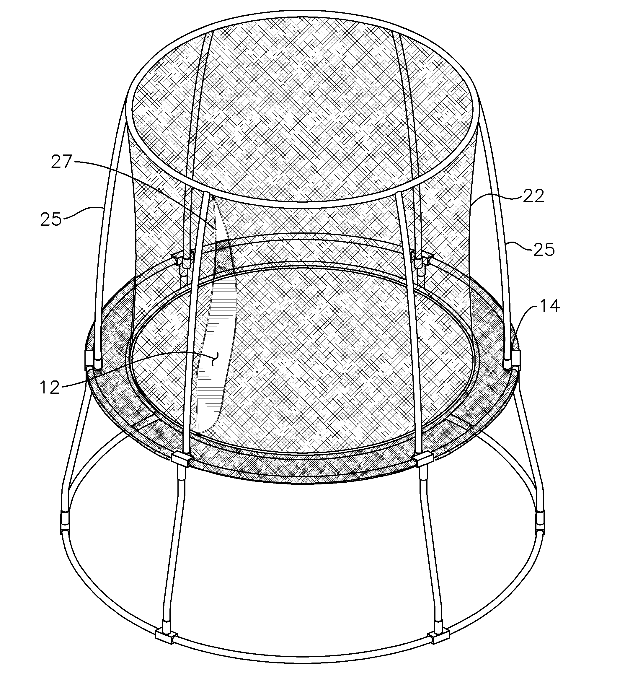
[0011] FIG. 1 is a perspective view of a trampoline with the connections between a trampoline's jumping surface and the protective netting enclosure in accordance with a preferred embodiment of the present invention and also having a door opening in the protective netting;
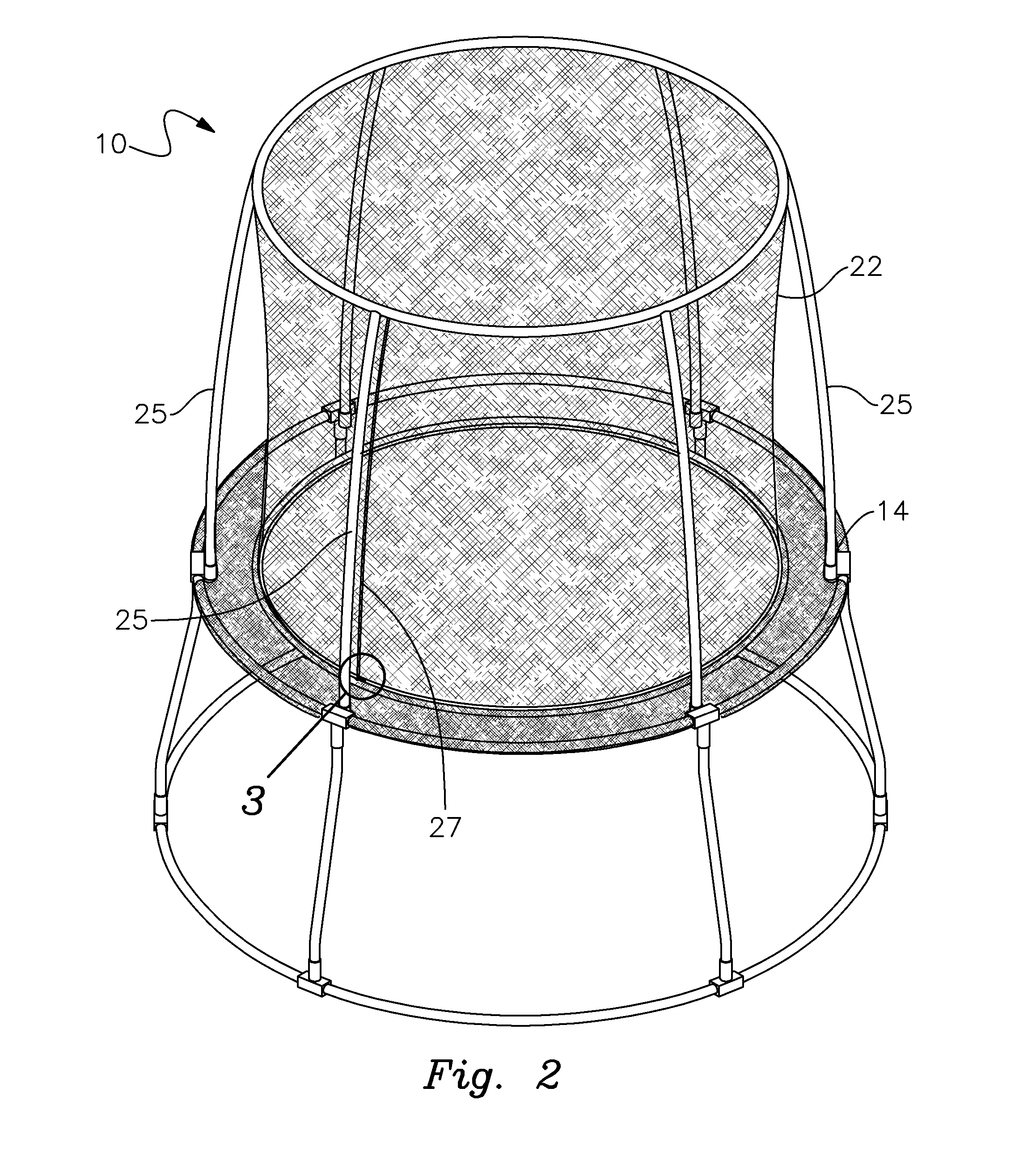
[0012] FIG. 2 is a perspective view of a trampoline as in FIG. 1 showing the door in the closed position;
[0013] FIG. 3 is a close-up view circled section 3 of FIG. 2; and
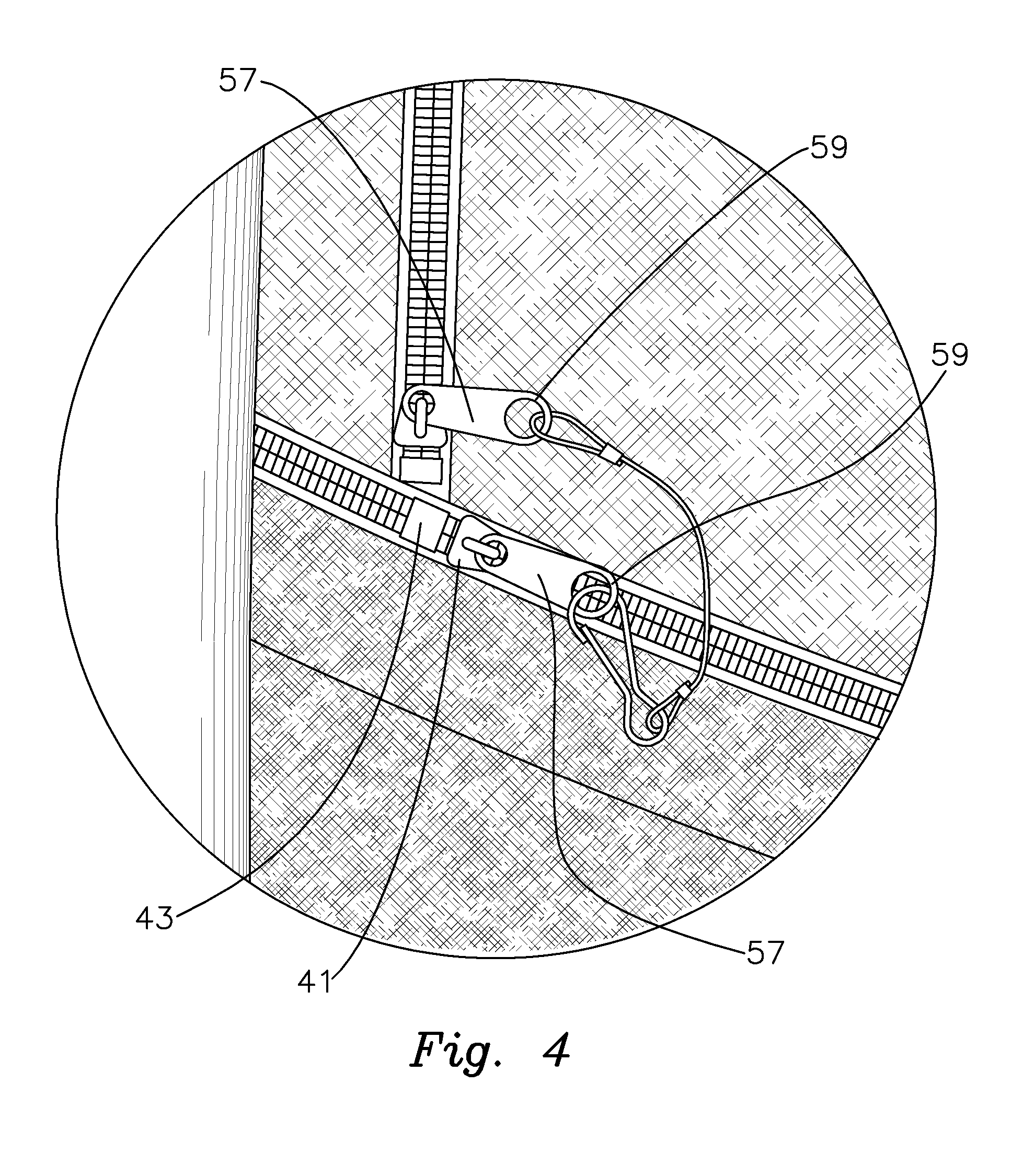
[0014] FIG. 4 is a view as in FIG. 3 showing the zipper tabs tethered together
DETAILED DESCRIPTION OF THE PREFERRED EMBODIMENTS
[0015] Detailed descriptions of the preferred embodiments are provided herein. It is to be understood, however, that the present invention may be embodied in various forms. Various aspects of the invention may be inverted, or changed in reference to specific part shape and detail, part location, or part composition. Therefore, specific details disclosed herein are not to be interpreted as limiting, but rather as a basis for the claims and as a representative basis for teaching one skilled in the art to employ the present invention in virtually any appropriately detailed system, structure or manner.
[0016] Turning first to FIGS. 1 and 2, there is shown trampoline 10 having a jumping surface 12. Trampoline jumping surface 12 is attached to rigid frame 14 by springs that are shown covered for protection. A protective mesh netting enclosure 22, is shown suspended from upright poles 25. Trampoline 10 in the illustrated embodiment is shown having separation 27 in protective netting enclosure 22 to allow a user access to jumping surface 12.
[0017] As shown at least in FIGS. 1 and 3, the connection between trampoline jumping surface 22 and trampoline protective netting enclosure 22 is by way of zipper 31. The illustrated embodiment, zipper 31 is of the open type configuration. Accordingly, first half 33 of zipper 31 includes a tape portion that is attached to trampoline mat 22. In the illustrated embodiment, first half 33 of zipper 31 is sewn to jumping surface 12. The mating, second half 35 of zipper 31 is attached to the bottom portion of trampoline protective netting enclosure 22. For purposes of the present invention, it does not matter which half of open zipper 31 is attached to trampoline jumping surface 12 and which is attached to trampoline protective netting enclosure 22, as long as the halves are matting, such that one half has the traditional box, and the other half has the traditional pin to be inserted into the box. Alternately, zipper 31 may be of a design having two pins. Regardless of zipper design, it is important that first half 33 of zipper 31 attached to trampoline jumping surface 12 and second half 35 of zipper 31 attached to protective netting enclosure 22 mate in the traditional zipper configuration.
[0018] In the preferred embodiment, zipper 31 is of a box and pin type design. Once the pin is inserted though zipper body 41 and into box 43, the two haves may be connected by pulling zipper tab 45 along the length of the two halves, ending close to the starting position. In this way, trampoline jumping surface 12 and protective netting enclosure 22 are connected. Further, in the preferred embodiment, zipper 31 is of the double sided design with a pull tabs on each side of zipper body 41, so that trampoline jumping surface 12 and trampoline protective netting enclosure 22 are connected along the length of their respective ends.
[0019] Also shown in FIGS. 1 and 2, is protective netting enclosure opening 27. Opening 27 is a separation in protective netting enclosure 22 so that a user my pass through from one side of protective netting enclosure 22 to the other side. In the illustrated embodiment, opening is shown as a vertical opening. Opening 27 is opened and closed by way of second or door zipper 51. In the illustrated embodiment, door zipper 51 has one half attached to one side of opening 27 and the other half attached to the other side of opening 27. Preferably, door zipper 51 is of the closed zipper design. Door zipper 51 is connect one half 53 to the other half 5 when door zipper 51 is in the down position, and generally disconnected throughout most of the length when door zipper 51 is in the upper position, as is shown in FIGS. 3 and 4. Door opening may be expanded by unzipping door zipper 51 and partially unzipping 31.
[0020] In the preferred embodiment, the terminal, closed position of zipper 31 and door zipper 51 are in proximity to each other. In this manner, the tabs of zipper 31 and door zipper 51 are also in close proximity when the two zippers are in the connected position through the length of each zipper. As illustrated in FIG. 4, holes 59 of tabs 57 of the two zippers 31, 51 may then be tethered together so that a person in the inside of protective netting enclosure 22 will not easily be able to unzip either zipper 31, or door zipper 51.
[0021] While the invention has been described in connection with preferred embodiments, it is not intended to limit the scope of the invention to the particular forms set forth, but on the contrary, it is intended to cover such alternatives, modifications, and equivalents as may be included within the spirit and scope of the invention as defined by the appended claims, and claims that may issue.
* * * * *
D00000
D00001
D00002
D00003
D00004
XML
uspto.report is an independent third-party trademark research tool that is not affiliated, endorsed, or sponsored by the United States Patent and Trademark Office (USPTO) or any other governmental organization. The information provided by uspto.report is based on publicly available data at the time of writing and is intended for informational purposes only.
While we strive to provide accurate and up-to-date information, we do not guarantee the accuracy, completeness, reliability, or suitability of the information displayed on this site. The use of this site is at your own risk. Any reliance you place on such information is therefore strictly at your own risk.
All official trademark data, including owner information, should be verified by visiting the official USPTO website at www.uspto.gov. This site is not intended to replace professional legal advice and should not be used as a substitute for consulting with a legal professional who is knowledgeable about trademark law.