Anvil Assembly With Snap Backup Ring
Penna; Christopher ; et al.
U.S. patent application number 16/171498 was filed with the patent office on 2019-02-28 for anvil assembly with snap backup ring. The applicant listed for this patent is Covidien LP. Invention is credited to Steven Joyce, Christopher Penna, Anthony Sgroi, JR..
| Application Number | 20190059902 16/171498 |
| Document ID | / |
| Family ID | 56345029 |
| Filed Date | 2019-02-28 |


View All Diagrams
| United States Patent Application | 20190059902 |
| Kind Code | A1 |
| Penna; Christopher ; et al. | February 28, 2019 |
ANVIL ASSEMBLY WITH SNAP BACKUP RING
Abstract
An anvil assembly is provided. The anvil assembly includes center rod assembly, a head assembly pivotal relative to the center rod assembly between an operative position and a tilted position, and a mechanism for selectively maintaining the head assembly in the operative position.
| Inventors: | Penna; Christopher; (Guilford, CT) ; Sgroi, JR.; Anthony; (Wallingford, CT) ; Joyce; Steven; (Wallingford, CT) | ||||||||||
| Applicant: |
|
||||||||||
|---|---|---|---|---|---|---|---|---|---|---|---|
| Family ID: | 56345029 | ||||||||||
| Appl. No.: | 16/171498 | ||||||||||
| Filed: | October 26, 2018 |
Related U.S. Patent Documents
| Application Number | Filing Date | Patent Number | ||
|---|---|---|---|---|
| 14790105 | Jul 2, 2015 | 10111668 | ||
| 16171498 | ||||
| Current U.S. Class: | 1/1 |
| Current CPC Class: | A61B 2017/07257 20130101; A61B 17/072 20130101; A61B 17/115 20130101; A61B 17/1155 20130101 |
| International Class: | A61B 17/115 20060101 A61B017/115; A61B 17/072 20060101 A61B017/072 |
Claims
1. (canceled)
2. An anvil assembly comprising: a center rod assembly; and a head assembly pivotally supported on the center rod assembly between an operative position and a tilted position, the head assembly including: a housing; a post extending from the housing and defining a first groove; and a backup member operably supported about the post, wherein the backup member is movable from a first position in which a portion of the backup member is positioned to prevent pivotal movement of the head assembly from the operative position to the tilted position, to a second position in which the backup member is positioned to permit pivotal movement of the head assembly from the operative position to a tilted position, the backup member including at least one locking feature receivable within the first groove of the post to maintain the backup member in the second position.
3. The anvil assembly according to claim 2, wherein the post further defines a second annular groove, the at least one locking feature being received within the second groove to maintain the backup member in the first position.
4. The anvil assembly according to claim 2, wherein the center rod assembly includes a center rod having at least one tab, wherein the at least one tab engages the backup member when the backup member is in the first position to maintain the head assembly in the operative position.
5. The anvil assembly according to claim 4, wherein movement of the backup member from the first position to the second position disengages the backup member from the at least one tab to permit the head assembly to move to the tilted position.
6. The anvil assembly according to claim 2, wherein the at least one locking feature is configured to prevent movement of the backup member from the first position to the second position until a predetermined force is applied to the backup member.
7. The anvil assembly according to claim 6, wherein the at least one locking feature is configured to flex radially outward when the predetermined force is applied to the backup member.
8. The anvil assembly according to claim 2, wherein the at least one locking feature includes a ridge configured for receipt within the second groove when the backup member is in the first position and within the first groove when the backup member is in the second position.
9. An anvil assembly comprising: a center rod assembly including a center rod having at least one tab; and a head assembly pivotally supported on the center rod assembly between an operative position and a tilted position, the head assembly including: a housing; a post extending proximally from the housing; and a backup member operably supported about the post, wherein the backup member is movable from a first position in which a portion of the backup member is positioned to prevent pivotal movement of the head assembly from the operative position to the tilted position, to a second position in which the backup member is positioned to permit pivotal movement of the head assembly from an operative position to the tilted position, the backup member including at least one detent configured to engage a proximal surface of the post to maintain the backup member in the first position, wherein the at least one tab engages the backup member when the backup member is in the first position to maintain the head assembly in the operative position.
10. The anvil assembly according to claim 9, wherein the post defines at least a first cutout for receiving the at least first detent when the backup member is in the second position.
11. The anvil assembly according to claim 9, wherein movement of the backup member from the first position to the second position disengages the backup member from the at least one tab to permit the head assembly to move to the tilted position.
12. The anvil assembly according to claim 9, wherein the at least one tab engages the at least first detent.
13. The anvil assembly according to claim 9, wherein the at least first detent is configured to prevent movement of the backup member from the first position to the second position until a predetermined force is applied to the backup member.
Description
CROSS-REFERENCE TO RELATED APPLICATIONS
[0001] The present application is a Continuation Application which claims that benefit of and priority to U.S. patent application Ser. No. 14/790,105, filed on Jul. 2, 2015, the entire content of which is incorporated herein by reference.
BACKGROUND
Technical Field
[0002] The present disclosure relates generally to an anvil assembly having a tiltable head which is suitable for use with a circular anastomosis stapler. More specifically, the present disclosure relates a tiltable anvil assembly having an improved retaining mechanism.
Background of Related Art
[0003] Circular anastomosis staplers which include an anvil assembly having a tiltable anvil head are known in the art. An example of such circular anastomosis stapler and tiltable anvil assembly are disclosed in commonly owned U.S. Pat. No. 7,364,060 ("the '060 patent"). A further example of a tiltable anvil assembly is disclosed in commonly owned U.S. Pat. No. 8,540,132 ("the '132 patent"). The content of each of the '060 patent and the '132 patent are incorporated herein by reference in their entirety. The anvil assembly described in the '132 patent includes a backup member located within the anvil assembly positioned to prevent tilting of the anvil head of the anvil assembly prior to firing of the stapler, e.g., in a proximal position. Upon firing of the stapler, a knife blade of the stapler engages and moves the backup member to a position, e.g., a distal position, which allows the anvil head to tilt upon retraction of the knife blade. If the backup member sticks to the knife blade upon retraction of the knife blade and/or is otherwise not retained in the distal position, the backup member may return to the proximal position, thereby preventing the anvil head from tilting.
[0004] In order to maintain the backup member in the proximal position where it prevents tilting of the anvil head prior to firing, the anvil assembly described in the '132 patent includes a retainer member positioned distal of the backup member. The retainer member includes a plurality of deformable tabs which prevent distal movement of the backup member until a predetermined force sufficient to deform the tabs is applied to the backup member, i.e., through engagement with the knife blade during staple formation. A residual proximal force is produced during deformation of the deformable tabs. This force acts on the backup member which may cause the backup member to move proximally towards its original position. As described in the '132 patent, the tilting operation of the anvil assembly relies on the distal positioning of the backup member following the firing of the stapler. Any proximal force that acts on the backup member may cause the backup member to return to the original proximal position, thereby preventing tilting of the anvil assembly.
[0005] Therefore, it would be beneficial to provide an anvil assembly with a mechanism or feature for retaining the backup member in the proximal position prior to firing of the stapling assembly, that allows the backup member to move to the distal position during firing of the stapling assembly, and that retains the backup member in the distal position after firing of the stapling assembly such that the anvil assembly may tilt.
SUMMARY
[0006] Accordingly, an anvil assembly is provided. The anvil assembly includes a center rod assembly and a head assembly pivotally supported on the center rod assembly between an operative position and a tilted position. The head assembly includes a housing, a post extending proximally from the housing and defining a proximal annular groove, and a backup member operably supported about the post, wherein the backup member is movable from a first position in which a portion of the backup member is positioned to prevent pivotal movement of the head assembly from the operative position to the tilted position, to a second position in which the backup member is positioned to permit pivotal movement of the head assembly from the operative position to a tilted position. The backup member includes a first locking feature and a second locking feature receivable within the proximal annular groove of the post to maintain the backup member in the first position.
[0007] In embodiments, the post further defines a distal annular groove, the first and second locking features being received within the distal annular groove to maintain the backup member in the second position. The center rod assembly may include a center rod having at least one tab. The at least one tab may engage the backup member when the backup member is in the first position to maintain the head assembly in the operative position. Movement of the backup member from the first position to the second position may disengage the backup member from the at least one tab to permit the head assembly to move to the tilted position.
[0008] The first and second locking features may be configured to prevent movement of the backup member from the first position to the second position until a predetermined force has been applied to the backup member. The first and second locking features may be configured to flex radially outward when the predetermined force is applied to the backup member. The first and second locking features may each include a ridge configured for receipt within the proximal annular groove when the backup member is in the first position and within the distal annular groove when the backup member is in the second position.
[0009] In embodiments, an anvil assembly in accordance with the present disclosure includes a center rod assembly, and a head assembly pivotally supported on the center rod assembly between an operative position and a tilted position. The head assembly includes a housing, a post extending proximally from the housing, and a backup member operably supported about the post, wherein the backup member is movable from a first position in which a portion of the backup member is positioned to prevent pivotal movement of the head assembly from the operative position to the tilted position, to a second position in which the backup member is positioned to permit pivotal movement of the head assembly from a operative position to the tilted position. The backup member includes a first detent and a second detent configured to engage a proximal surface of the post to maintain the backup member in the first position.
[0010] In embodiments, the post defines first and second cutouts for receiving the respective first and second detents when the backup member is in the second position. The center rod assembly may include a center rod having at least one tab, wherein the at least one tab engages the backup member when the backup member is in the first position to maintain the head assembly in the operative position. Movement of the backup member from the first position to the second position may disengage the backup member from the at least one tab to permit the head assembly to move to the tilted position. The at least one tab may engage one of the first and second detents. The first and second detents may be configured to prevent movement of the backup member from the first position to the second position until a predetermined force has been applied to the backup member.
BRIEF DESCRIPTION OF THE DRAWINGS
[0011] Various embodiments of the presently disclosed anvil assembly are disclosed herein with reference to the drawings wherein:
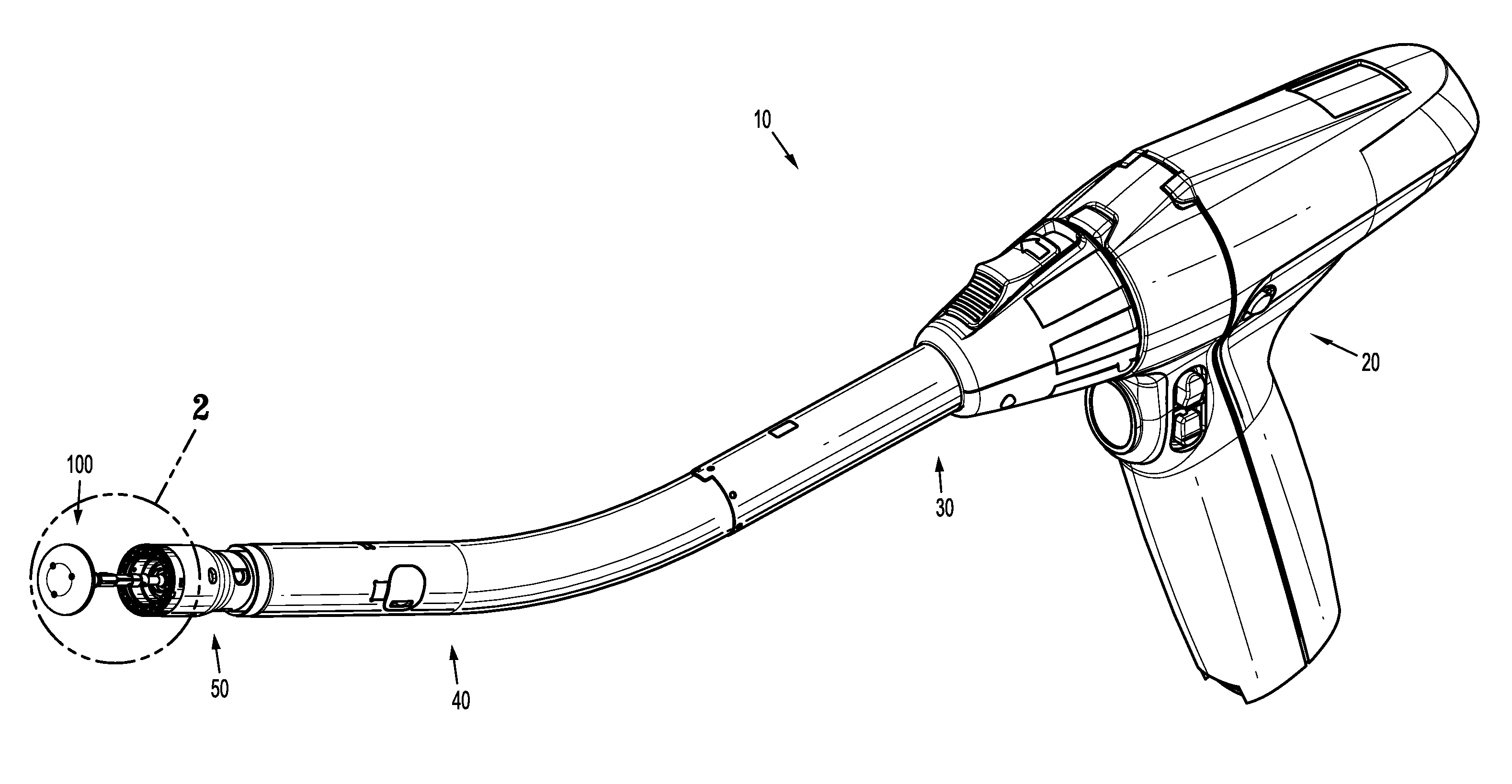
[0012] FIG. 1 is a perspective side view of a surgical stapling device including an embodiment of an anvil assembly according to the present disclosure;
[0013] FIG. 2 is enlarged view of the indicated area of detail shown in FIG. 1;
[0014] FIG. 3 is a cross-sectional side view taken along line 3-3 shown in FIG. 2, illustrating the anvil assembly approximated against a loading unit;
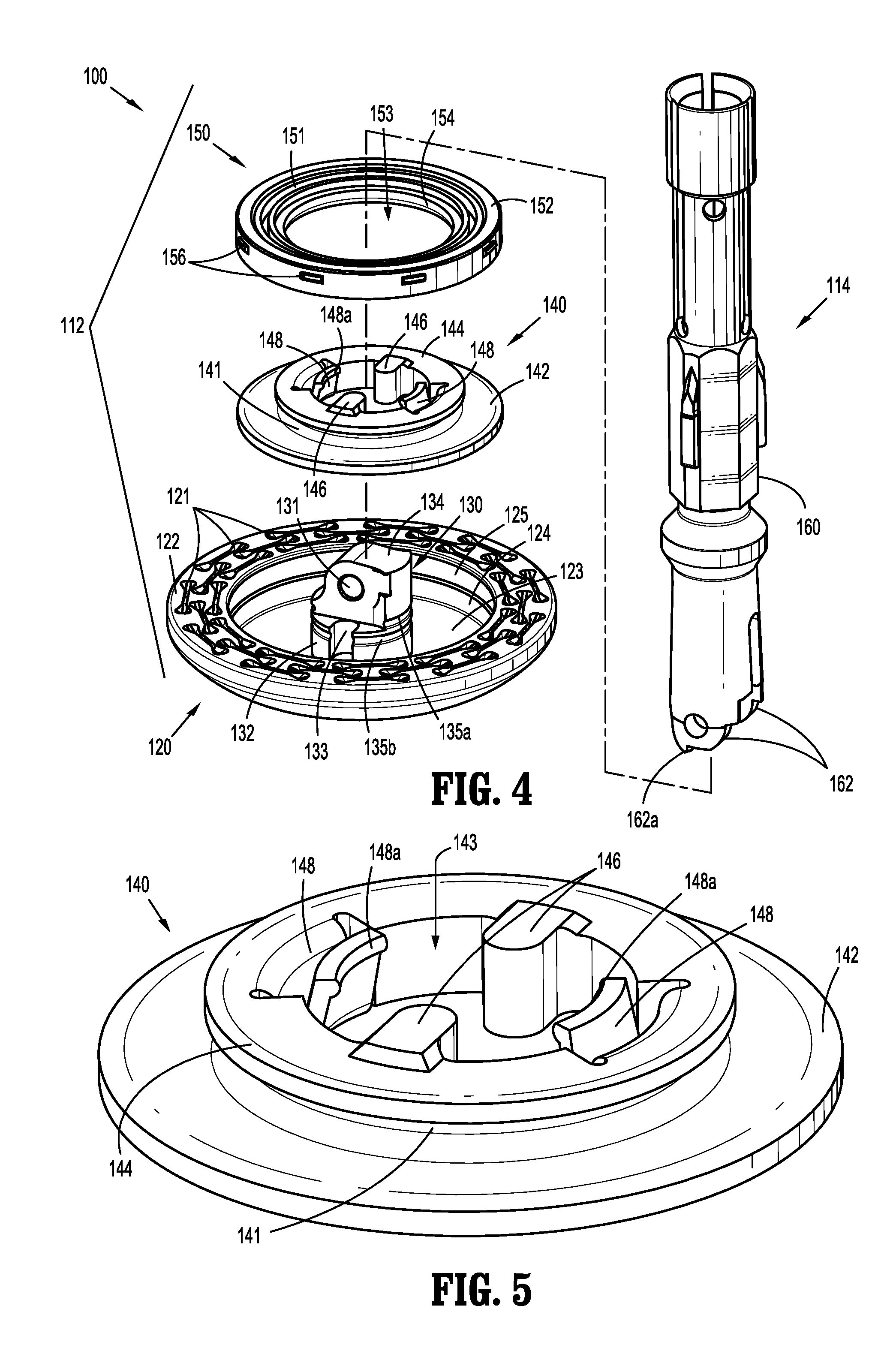
[0015] FIG. 4 is a perspective side view of the anvil assembly shown in FIG. 1 with the parts separated;
[0016] FIG. 5 is a perspective side view of a backup member of the anvil assembly shown in FIG. 4;
[0017] FIG. 6 is a perspective side view of the anvil assembly shown in FIG. 4;
[0018] FIG. 7 is an enlarged view of the indicated area of detail shown in FIG. 6;
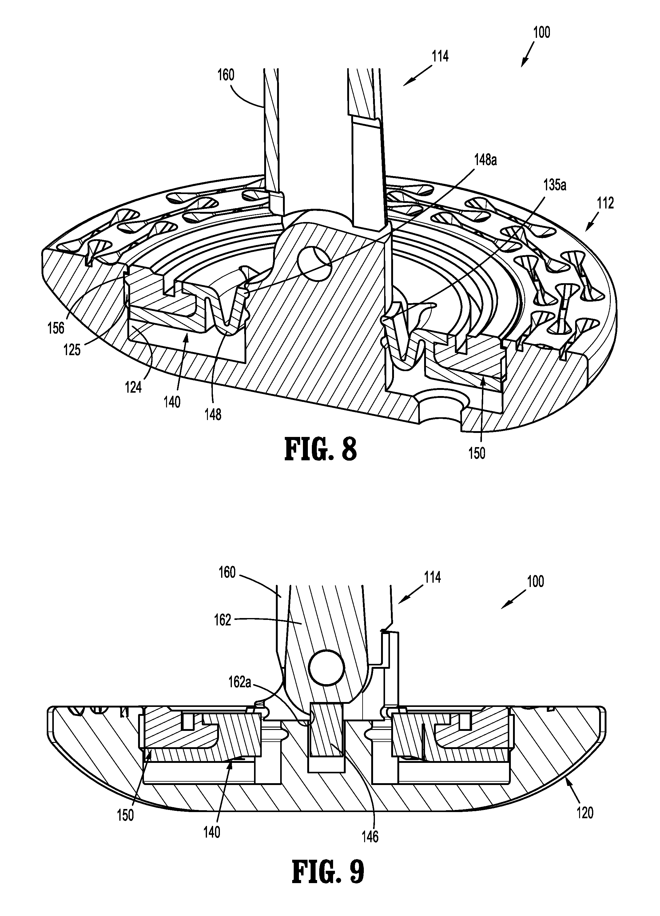
[0019] FIG. 8 is a cross-sectional perspective view taken along line 8-8 shown in FIG. 7;
[0020] FIG. 9 is a cross-sectional side view taken along line 9-9 shown in FIG. 7;
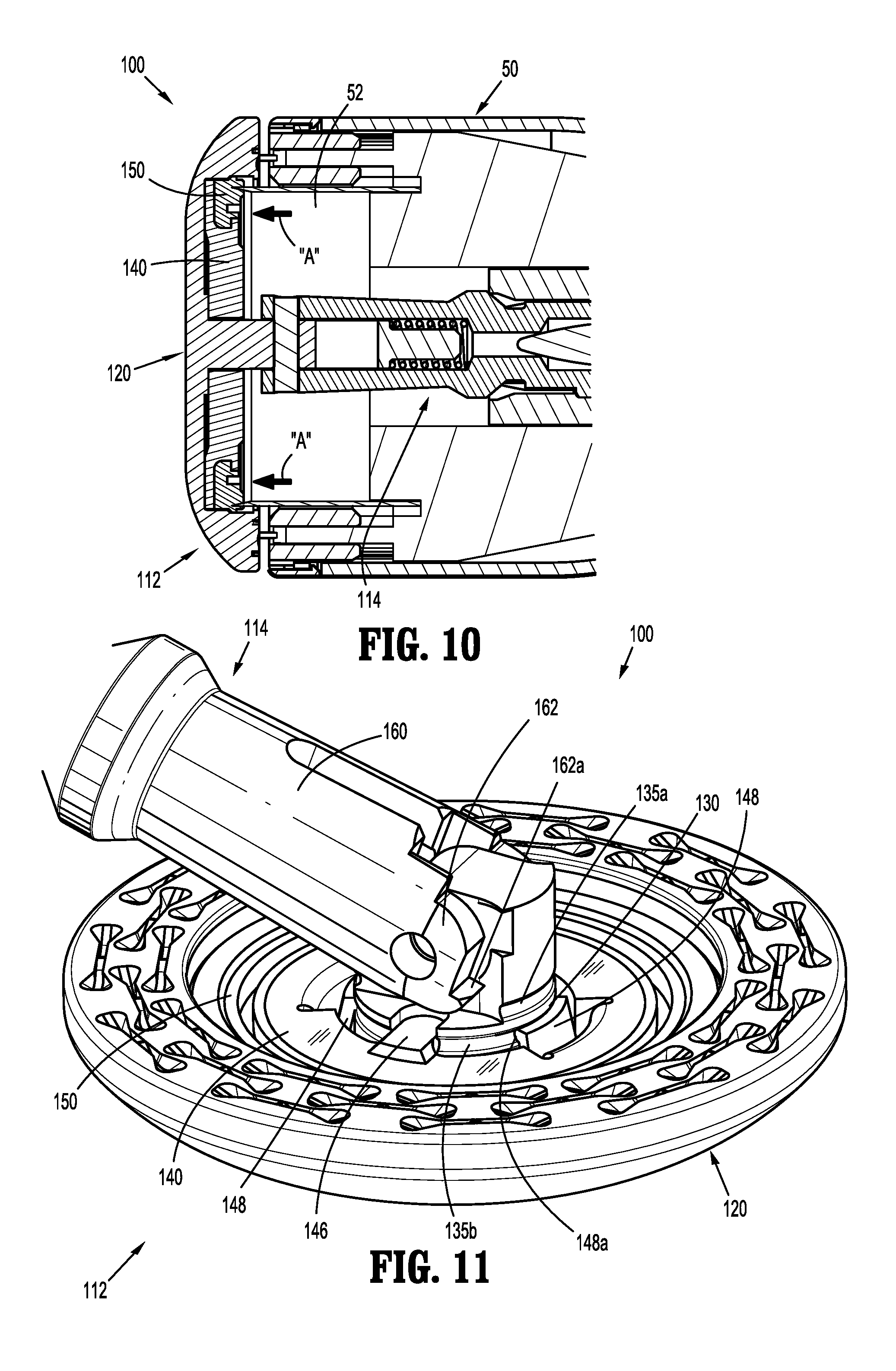
[0021] FIG. 10 is a cross-sectional side view taken along line 3-3 shown in FIG. 2, during a tissue cutting stroke;
[0022] FIG. 11 is a perspective top view of a head assembly of the anvil assembly shown in FIG. 4 subsequent to firing of the surgical stapling device show in FIG. 1;
[0023] FIG. 12 is a cross-sectional perspective view taken along line 8-8 shown in FIG. 7 subsequent to tilting of the head assembly;
[0024] FIG. 13 is a cross-sectional side view taken along line 9-9 shown in FIG. 7, subsequent to tilting of the head assembly;
[0025] FIG. 14 is a perspective view of another embodiment of an anvil assembly according to the present disclosure;
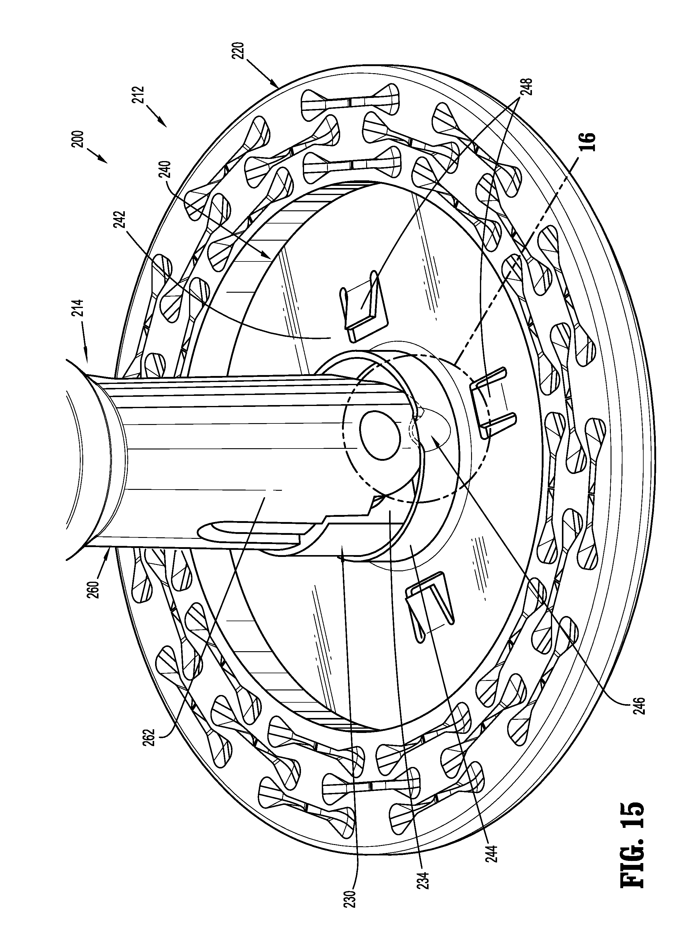
[0026] FIG. 15 is an enlarged perspective view a head assembly of the anvil assembly shown in FIG. 14 with a cutting ring removed and a backup member in a proximal position;
[0027] FIG. 16 is an enlarged view of the indicated area of detail shown in FIG. 15;
[0028] FIG. 17 is an enlarged perspective view of the head assembly of the anvil assembly shown in FIG. 14 with the backup member in a distal position; and
[0029] FIG. 18 is a perspective side view of the anvil assembly shown in FIG. 14 with the head assembly in a tilted position and the backup member and the cutting ring removed.
DETAILED DESCRIPTION OF EMBODIMENTS
[0030] Embodiments of the presently disclosed anvil assembly will now be described in detail with reference to the drawings in which like reference numerals designate identical or corresponding elements in each of the several views. As is common in the art, the term "proximal" refers to that part or component closer to the user or operator, i.e. surgeon or clinician, while the term "distal" refers to that part or component further away from the user.
[0031] Referring initially to FIGS. 1-3, an anvil assembly according to an embodiment of the present disclosure, shown generally as anvil assembly 100, is secured to a surgical stapling device 10. The surgical stapling device 10 includes a powered handle 20, an adapter assembly 30, an extension assembly 40, and a loading unit 50. Although shown and described with reference to anvil assembly 100 and surgical stapling device 10, the aspects of the present disclosure may be modified for use with anvil assemblies having alternative configurations, with manual surgical stapling devices having various configurations, and with powered surgical stapling devices having alternative configurations. For a detailed description of an exemplary surgical stapling device, please refer to commonly owned U.S. Pat. No. 9,023,014 ("the '014 patent) and U.S. Pat. Appl. Publ. No. 2012/0253329 ("the '329 application"), the contents of which are incorporated by reference herein in their entirety.
[0032] Referring to FIGS. 2-4, briefly, the anvil assembly 100 includes a head assembly 112 pivotally secured to a center rod assembly 114. The head assembly 112 includes a housing 120, a post 130, a backup member 140, and a cutting ring 150. The center rod assembly 114 includes a center rod 160 and a biasing mechanism 170 (FIG. 3) operably received within a distal bore 161 (FIG. 3) of the center rod 160. The biasing mechanism 170 facilitates moving of the head assembly 112 relative to the center rod 160 between at least an operative position (FIG. 6) and a tilted position (FIG. 11). The biasing mechanism 170 includes a plunger member 172 (FIG. 3) and a biasing member, e.g., a compression spring 174 (FIG. 3). For a detailed description of an exemplary center rod assembly 114, please refer to the '132 patent, the contents of which were previously incorporated by reference herein.
[0033] With continued reference to FIGS. 3 and 4, the housing 120 of the head assembly 112 of the anvil assembly 100 defines a plurality of staple forming pockets 121 on a proximal facing surface 122 thereof. Alternatively, the head assembly 112 may include an anvil plate (not shown), defining a plurality of staple forming pockets (not shown), supported on the proximal facing surface 122 of the housing 120. The housing 120 further defines a cavity 123 between an inner wall 124 and the post 130 for operably receiving the backup member 140 and the cutting ring 150. As will be described in further detail below, the inner wall 124 of the housing 120 defines an annular groove 125 for receiving a plurality of tabs 156 of the cutting ring 150.
[0034] As shown, the post 130 of the head assembly 112 is monolithically formed with and centrally positioned within the housing 120. Alternately, the housing 120 and the post 130 are formed separately and fastened together using a known fastening technique, e.g., adhesive, welding, friction fit, etc. The post 130 includes a substantially cylindrical body 132 having a projection 134, and defining opposed cutouts 133 and proximal and distal annular grooves 135a, 135b. The projection 134 of the post 130 defines a throughbore 131 and is configured to operably engage the center rod 160 of the center rod assembly 114. More particularly, the projection 134 of post 130 is received between extensions 162 of the center rod 160 of the center rod assembly 114 and is pivotally secured to the center rod 160 by a pivot pin 162 received through the throughbore 131.
[0035] With additional reference to FIG. 5, the backup member 140 of the head assembly 112 includes an annular body 142 and an annular flange 144 extending from the annular body 142. The backup member 140 defines an annular groove 141 disposed between the annular body 142 and the annular flange 144, and a central opening 143 extending through the annular body 142 and the annular flange 144. The backup member 140 is operably receivable within the cavity 123 of the housing 120 of the head assembly 112 about the post 130. The backup member 140 includes opposed protrusions 146 extending within the central opening 143 and receivable within the opposed cutouts 133 of the post 130 when the backup member 140 is received within the cavity 123 of the housing 120. As will be described in further detail below, when the backup member 140 is in a proximal position (FIG. 3), the opposed protrusions 146 engage tabs 162a formed on the extensions 162 of the center rod 160 of the center rod assembly 114 to maintain the head assembly 112 in an operative position (FIG. 3).
[0036] With particular reference still to FIG. 5, the backup member 140 further includes opposed locking features 148 that frictionally engage the post 130 when the backup member 140 is received within the cavity 121 of the housing 120 and about the post 130. More particularly, each of the opposed locking features 148 forms a resilient member that includes a ridge 148a selectively receivable within the proximal and distal annular grooves 135a, 135b of the post 130. When the ridges 148a of the opposed locking features 148 of the backup member 140 are received within the proximal annular groove 135a of the post 130, the opposed locking features 148 operate to maintain the backup member 140 in the proximal position (FIG. 3). Although shown including two locking features 148, it is envisioned that the backup member 140 may include three (3) or more locking features 148.
[0037] When a predetermined force is applied to the backup member 140 in the distal direction, the opposed locking features 148 of the backup member 140 are configured to flex radially outwardly as the backup member 140 moves in a distal direction. The radial outward flexion of the ridges 148a of the opposed locking features 148 retract the ridges 148a from within the proximal annular groove 135a, thereby permitting continued distal movement of the backup member 140. The distal annular groove 135b of the post 130 is positioned such that when the backup member 140 is moved to the distal position (FIG. 13), the ridges 148a of the opposed locking features 148 align with and are subsequently received within the distal annular groove 135b because of the resilient nature of the opposed locking features 148.
[0038] With continued reference to FIGS. 3 and 4, the cutting ring 150 of the head assembly 112 of the anvil assembly 100 includes an annular body 152 and defines an annular groove 151 and a central opening 153. The cutting ring 150 is secured about the annular flange 144 of the backup member 140 and includes an inwardly extending lip 154 that is received within the annular groove 143 of the backup member 140 for securing the cutting ring 150 to the backup member 140. As noted above, a plurality of tabs 156 extend outwardly from the annular body 152 of the cutting ring 150. The plurality of tabs 156 are received within the annular groove 125 formed in the inner wall 124 of the housing 120 when the cutting ring 150 is received within the cavity 123 of the housing 120. The plurality of tabs 156 maintains the backup member 140 and the cutting ring 150 within the housing 120 of the head assembly 112.
[0039] Although the cutting ring 150 is shown and described as being formed as an independent component that is secured to the backup member 140 by placing the cutting ring 150 around the annular flange 144 of the backup member 140 and receiving the lip 154 of the cutting ring 150 within the annular groove 143 of the backup member 140, it is envisioned that the backup member 140 and the cutting ring 150 may be integrally formed, or formed as a one piece or monolithic structure.
[0040] With reference now to FIGS. 6-9, the anvil assembly 100 is shown with the head assembly 112 in the operative position. In the operative position, the backup member 140 and the cutting ring 150 are in the proximal position. When the backup member 140 and the cutting ring 150 are in the proximal position, the ridges 148a of the opposed locking features 148 of the backup member 140 are received within the proximal annular groove 135a of the post 130 to maintain the backup member 140 and the cutting ring 150 in the proximal position. Additionally, the plurality of tabs 156 (FIG. 8) of the cutting ring 150 are received within the annular groove 125 formed in the inner surface 124 of the housing 120 to maintain the backup member 140 and the cutting ring 150 within the cavity 123 of the housing 120.
[0041] As noted above, the head assembly 112 of the anvil assembly 100 is maintained in the operative position by the backup member 140 when the backup member 140 is in the proximal position. In particular, the opposed protrusions 146 of the backup member 140 engage the tabs 162a extending from the extension 162 of the center rod 160 of the center rod assembly 114 to prevent the head assembly 112 from pivoting to the tilted position (FIG. 11) relative to the center rod 160.
[0042] With reference now to FIG. 10, during actuation of surgical stapling device 10, subsequent to the stapling of tissue in a two stroke stapling device, or concurrently with the stapling of tissue in a single stroke device, the knife 52 of the loading unit 50 is advanced into contact with the cutting ring 150 of the head assembly 112 of the anvil assembly 100. Since the cutting ring 150 is secured to the backup member 140, the force applied to the cutting ring 150 is transferred to the backup member 150. As noted above, when the predetermined force is applied to the backup member 140, the opposed locking features 148 of the backup member 140 flex radially outwardly to retract the ridges 148a of the opposed locking features 148 from within the proximal annular groove 135a of the post 130 to allow the backup member 140 to move relative to the post 130.
[0043] Turning now to FIGS. 11-13, the anvil assembly 100 is shown with the backup member 140 and the cutting ring 150 in the distal position. As the backup member 140 moves to the distal position, the opposed protrusions 144 of the backup member 140 disengage from the tabs 162a formed on the extensions 162 of the center rod 160 of the center rod assembly 114 to permit the head assembly 112 to pivot relative to the center rod assembly 114. As noted above, when the backup member 140 is in the distal position, the ridges 148a of the opposed locking features 148 align with and are received within the distal annular groove 135b of the post 130 to lock the backup member 140 in the distal position.
[0044] It is noted that the anvil head assembly 100 will not immediately tilt or pivot to the tilted position upon firing of the surgical stapling device 10 because, upon firing, the head assembly 100 is in an approximated position, i.e., the head assembly 100 is in close alignment with the loading unit 50 of the surgical stapling device 10 (FIG. 10). As such, the head assembly 100 is prevented from tilting until the head assembly 112 is moved away from the loading unit 50.
[0045] With reference to FIGS. 14-18, another embodiment of an anvil assembly according to the present disclosure is shown generally as anvil assembly 200. The anvil assembly 200 is substantially similar to the anvil assembly 100 described hereinabove and will only be described in detail as relates to the differences therebetween.
[0046] The anvil assembly 200 includes a head assembly 212 and a center rod assembly 214. The head assembly 212 includes a housing 220, a post 230, a backup member 240, and a cutting ring 250. The center rod assembly includes a center rod 260 and a biasing assembly 270 (FIG. 18). The housing 220 is substantially similar to housing 120 and will not be described any further herein.
[0047] The post 230 of the head assembly 212 is centrally disposed within the housing 220 and includes a substantially cylindrical body 232. A projection 234 extends proximally from the cylindrical body 232 and is pivotally secured to extensions 262 of the center rod 260. The cylindrical body 232 of the post 230 defines opposed cutouts 233. As will be described in further detail below, the opposed cutouts 233 facilitate securing the backup member 240 in a distal position (FIG. 17).
[0048] The backup member 240 includes a substantially planar body 242 and an annular flange 244 extending proximally from the planar body 242. The annular flange 244 is receivable about the post 230 and includes opposed detents 246 formed on a proximal end of the annular flange 244. The opposed detents 246 operate to maintain the backup member 240 in the proximal position prior to actuation of the surgical stapler 10 (FIG. 1) and in the distal position subsequent to actuation of the surgical stapler 10. The opposed detents 246 further operate to maintain the head assembly 212 in the operative position when the backup member 240 is in the proximal position. Although shown including two detents 246, it is envisioned that the backup member 140 may include three (3) or more detents 246.
[0049] The backup member 240 includes a plurality of tangs 248 for securing the cutting ring 250 to the backup member 240. Although shown including a plurality of tangs 248, it is envisioned that the cutting ring 250 may be secured to the backup member 240 in any suitable manner. The cutting ring 250 is substantially similar to the cutting ring 150 described hereinabove and will not be described in further detail herein.
[0050] With reference to FIGS. 14-16, when the backup member 240 is in the proximal position, a distal portion 246b of the opposed detents 246 engages a top surface 232a (FIG. 16) of the cylindrical body 232 of the post 230 to maintain the backup member 240 in the proximal position. When the backup member 240 is in the proximal position, the opposed detents 246 are aligned with the tabs 262a formed on the extension 262 of the center rod 260 of the center rod assembly 214 to maintain the head assembly 212 in the operative position.
[0051] When a predetermined force is applied to the backup member 240, e.g., by knife 52 (FIG. 10) during actuation of the surgical stapler 10, the opposed detents 246 flex radially outwardly as the backup member 240 moves distally about the cylindrical body 232 of the post 230 to permit movement of the backup member 240 to the distal position. The post 230 may include a longitudinal slot (not shown) for receiving the detents 246 and facilitating distal movement of the backup member 240 from the proximal position to the distal position.
[0052] When the backup member 240 is in the distal position, the opposed detents 246 of the backup member 240 are received within the opposed cutout 233 of the post 230 to secure the backup member 240 in the distal position. More particularly, a proximal surface 246a of the opposed detents 246 engages the cylindrical body 232 of the post 230 when the detents 246 are received in the cutouts 233 of the post 230 to maintain the backup member 240 in the distal position.
[0053] Persons skilled in the art will understand that the devices and methods specifically described herein and illustrated in the accompanying drawings are non-limiting exemplary embodiments. It is envisioned that the elements and features illustrated or described in connection with one exemplary embodiment may be combined with the elements and features of another without departing from the scope of the present disclosure. As well, one skilled in the art will appreciate further features and advantages of the disclosure based on the above-described embodiments. Accordingly, the disclosure is not to be limited by what has been particularly shown and described, except as indicated by the appended claims.
* * * * *
D00000
D00001
D00002
D00003
D00004
D00005
D00006
D00007
D00008
D00009
D00010
D00011
XML
uspto.report is an independent third-party trademark research tool that is not affiliated, endorsed, or sponsored by the United States Patent and Trademark Office (USPTO) or any other governmental organization. The information provided by uspto.report is based on publicly available data at the time of writing and is intended for informational purposes only.
While we strive to provide accurate and up-to-date information, we do not guarantee the accuracy, completeness, reliability, or suitability of the information displayed on this site. The use of this site is at your own risk. Any reliance you place on such information is therefore strictly at your own risk.
All official trademark data, including owner information, should be verified by visiting the official USPTO website at www.uspto.gov. This site is not intended to replace professional legal advice and should not be used as a substitute for consulting with a legal professional who is knowledgeable about trademark law.