Slide Fastener
Minato; Tsuyoshi ; et al.
U.S. patent application number 15/683089 was filed with the patent office on 2019-02-28 for slide fastener. The applicant listed for this patent is YKK Corporation. Invention is credited to Yusuke Hosokawa, Tsuyoshi Minato, Suguru Ogura, Mingsi Wang.
| Application Number | 20190059524 15/683089 |
| Document ID | / |
| Family ID | 65434523 |
| Filed Date | 2019-02-28 |


View All Diagrams
| United States Patent Application | 20190059524 |
| Kind Code | A1 |
| Minato; Tsuyoshi ; et al. | February 28, 2019 |
SLIDE FASTENER
Abstract
A fastening device includes a first tape portion and a first fastening portion joined thereto, the first fastening portion defining a first side surface and a second side surface opposite thereto, the first fastening portion including a plurality of fastening elements extending from the first side surface, the plurality of fastening elements arranged lengthwise along a lengthwise direction of the fastening device, each adjacent pair of fastening elements offset by a pitch distance and defining a fastening gap therebetween, each of the plurality of fastening elements including an engagement portion extending in a direction parallel to the lengthwise direction, each of the plurality of fastening elements being asymmetric about a protrusional centerline of the fastening element, the fastening device being a first fastening device configured to be joined to a second fastening device comprising a second fastening portion having the same geometry as the first fastening portion.
| Inventors: | Minato; Tsuyoshi; (Macon, GA) ; Ogura; Suguru; (Macon, GA) ; Wang; Mingsi; (Macon, GA) ; Hosokawa; Yusuke; (Kurobe, JP) | ||||||||||
| Applicant: |
|
||||||||||
|---|---|---|---|---|---|---|---|---|---|---|---|
| Family ID: | 65434523 | ||||||||||
| Appl. No.: | 15/683089 | ||||||||||
| Filed: | August 22, 2017 |
| Current U.S. Class: | 1/1 |
| Current CPC Class: | A44B 18/0073 20130101; A44B 19/32 20130101; A44B 19/10 20130101; A44B 19/26 20130101; A44B 18/0007 20130101 |
| International Class: | A44B 18/00 20060101 A44B018/00; A44B 19/10 20060101 A44B019/10; A44B 19/26 20060101 A44B019/26; A44B 19/32 20060101 A44B019/32 |
Claims
1. A fastening system comprising: a first fastening device comprising a first fastening portion and a first tape portion joined to the first fastening portion, the first fastening portion comprising a base defining a first side surface and a second side surface opposite from the first side surface, the first fastening portion comprising a plurality of fastening elements extending from the first side surface of the base of the first fastening portion, the plurality of fastening elements arranged lengthwise along a lengthwise direction of the first fastening device, each adjacent pair of fastening elements offset by a pitch distance and defining a fastening gap therebetween to define a plurality of fastening gaps of the first fastening portion, each of the plurality of fastening elements comprising an engagement portion extending in a direction parallel to the lengthwise direction of the first fastening device, the second side surface of the first fastening portion defining a plurality of relief grooves, the plurality of relief grooves substantially aligned in the lengthwise direction of the first fastening device with a fastening element of the first fastening portion of the first fastening device; and a second fastening device comprising a second fastening portion and a second tape portion joined to the second fastening portion, the second fastening portion comprising a base defining a first side surface and a second side surface opposite from the first side surface, the second fastening portion comprising a plurality of fastening elements extending from the first side surface of the base of the second fastening portion, the plurality of fastening elements arranged lengthwise along a lengthwise direction of the second fastening device, each adjacent pair of fastening elements offset by the pitch distance and defining a fastening gap therebetween to define a plurality of fastening gaps of the second fastening portion, each of the plurality of fastening elements comprising an engagement portion extending in a direction parallel to the lengthwise direction of the second fastening device, the second side surface of the second fastening portion defining a plurality of relief grooves, the plurality of relief grooves substantially aligned in the lengthwise direction of the second fastening device with a fastening element of the second fastening portion of the second fastening device; wherein the second fastening portion of the second fastening device is configured to fasten to the first fastening portion of the first fastening device when the first side surface of the second fastening portion is facing the first side surface of the first fastening portion, each of the plurality of fastening gaps of the first fastening portion sized to lockably receive a one of the plurality of fastening elements of the second fastening portion and each of the plurality of fastening gaps of the second fastening portion sized to lockably receive a one of the plurality of fastening elements of the first fastening portion.
2. The system of claim 1, wherein the first tape portion and the plurality of fastening elements of the first fastening device are formed monolithically with each other and the second tape portion and the plurality of fastening elements of the second fastening device are formed monolithically with each other.
3. The system of claim 1, wherein the plurality of fastening elements of the first fastening device define a first row of fastening elements substantially aligned in the lengthwise direction of the first fastening device and the plurality of fastening elements of the second fastening device define a first row of fastening elements substantially aligned in the lengthwise direction of the second fastening device; the first fastening device further comprising a second row of fastening elements substantially aligned in the lengthwise direction of the first fastening device and positioned parallel to the first row of fastening elements of the first fastening device and the second fastening device further comprising a second row of fastening elements substantially aligned in the lengthwise direction of the second fastening device and positioned parallel to the first row of fastening elements of the second fastening device.
4. The system of claim 3, wherein each of the plurality of fastening elements in the second row of fastening elements of each of the first fastening device and the second fastening device comprises an engagement portion extending in a direction parallel to the lengthwise direction of the respective fastening device and opposite to the direction in which the engagement portions of the plurality of fastening elements in the first row of fastening elements of the respective fastening device extend.
5. The system of claim 1, wherein each of the plurality of fastening elements is asymmetric about a protrusional centerline of the fastening element.
6. The system of claim 1, wherein the first tape portion and the second tape portion are substantially coplanar.
7. The system of claim 1, wherein a wall of the first fastening device extending between a first row of fastening elements and a second row of fastening elements comprises a seal configured to create a watertight seal against the second fastening device during assembly of the second fastening device with the first fastening device.
8. The system of claim 1, further comprising a slider simultaneously coupled to both the first fastening device and the second fastening device and configured to selectively engage and disengage the second fastening device from the first fastening device.
9. A fastening device comprising: a first tape portion; and a first fastening portion joined to the first tape portion, the first fastening portion defining a first side surface and a second side surface opposite from the first side surface, the first fastening portion comprising a plurality of fastening elements extending from the first side surface, the plurality of fastening elements arranged lengthwise along a lengthwise direction of the fastening device, each adjacent pair of fastening elements offset by a pitch distance and defining a fastening gap therebetween, each of the plurality of fastening elements comprising an engagement portion extending in a direction parallel to the lengthwise direction of the fastening device, each of the plurality of fastening elements being asymmetric about a protrusional centerline of the fastening element, the fastening device being a first fastening device, the first fastening device configured to be joined to a second fastening device comprising a second fastening portion having the same geometry as the first fastening portion of the first fastening device.
10. The first fastening device of claim 9, wherein the first fastening portion is monolithically formed with the first tape portion.
11. The first fastening device of claim 9, wherein the plurality of fastening elements define a first row of fastening elements substantially aligned in the lengthwise direction of the first fastening device; the first fastening device further comprising a second row of fastening elements substantially aligned in the lengthwise direction of the first fastening device and positioned parallel to the first row of fastening elements of the first fastening device.
12. The first fastening device of claim 11, wherein the first row of fastening elements and the second row of fastening elements define a lateral gap distance between the first row of fastening elements and the second row of fastening elements.
13. The first fastening device of claim 11, wherein laterally adjacent fastening elements of the first fastening portion are symmetric about a point positioned halfway between the laterally adjacent fastening elements when viewing the first side surface of the first fastening device.
14. The first fastening device of claim 11, further comprising a wall extending from the first side between the first row of fastening elements and the second row of fastening elements.
15. The first fastening device of claim 14, wherein the wall is segmented.
16. The first fastening device of claim 11, further comprising a third row of fastening elements and a fourth row of fastening elements, the third row of fastening elements substantially aligned in the lengthwise direction of the first fastening device and positioned adjacent to and offset from the first row of fastening elements of the first fastening device in a direction extending away from the second row of fastening elements, the fourth row of fastening elements substantially aligned in the lengthwise direction of the first fastening device and positioned adjacent to and offset from the second row of fastening elements of the first fastening device in a direction extending away from the first row of fastening elements.
17. The first fastening device of claim 9, wherein the second side surface of the first fastening portion defines a plurality of relief grooves.
18. A fastening device comprising: a first tape portion; and a first fastening portion joined to the first tape portion, the first fastening portion defining a first side surface and a second side surface opposite from the first side surface, the first fastening portion comprising a plurality of fastening elements extending from the first side surface, the plurality of fastening elements arranged lengthwise along a lengthwise direction of the fastening device, each adjacent pair of fastening elements offset by a pitch distance and defining a fastening gap therebetween, each of the plurality of fastening elements comprising an engagement portion extending in a direction parallel to the lengthwise direction of the fastening device, the fastening device being a first fastening device, the first fastening device configured to be joined to a second fastening device comprising a second fastening portion having the same geometry as the first fastening portion of the first fastening device.
19. The first fastening device of claim 18, wherein each of the plurality of fastening elements is asymmetric about a protrusional centerline of the fastening element.
20. The first fastening device of claim 18, wherein the second side surface of the first fastening portion defines a plurality of relief grooves.
Description
TECHNICAL FIELD
Field of Use
[0001] This disclosure relates to fastening systems. More specifically, this disclosure relates to a fastening system for joining two fastening devices such as a pair of slide fasteners to each other.
Related Art
[0002] Fasteners are commonly used to join two panels of material, such as two panels of a piece of clothing, two panels of a piece of upholstery, or two different parts of packaging such as the sides of an opening of a sealed bag. With varying degrees of flexibility, typical slide fasteners are made from multiple components (e.g., metal, plastic, and fabric) and materials and as a result can be more costly to manufacture and even assemble to the end product. The prospect of being able to use a relatively low cost manufacturing process, such as an extrusion process with even multiple materials, to make many thousands of feet of fastener material is attractive but has not generally been practical due to the inflexibility and/or weakness of the resulting fastened joint.
SUMMARY
[0003] It is to be understood that this summary is not an extensive overview of the disclosure. This summary is exemplary and not restrictive, and it is intended to neither identify key or critical elements of the disclosure nor delineate the scope thereof. The sole purpose of this summary is to explain and exemplify certain concepts of the disclosure as an introduction to the following complete and extensive detailed description.
[0004] In one aspect, disclosed is a fastening system comprising: a first fastening device comprising a first fastening portion and a first tape portion joined to the first fastening portion, the first fastening portion comprising a base defining a first side surface and a second side surface opposite from the first side surface, the first fastening portion comprising a plurality of fastening elements extending from the first side surface of the base of the first fastening portion, the plurality of fastening elements arranged lengthwise along a lengthwise direction of the first fastening device, each adjacent pair of fastening elements offset by a pitch distance and defining a fastening gap therebetween, each of the plurality of fastening elements comprising an engagement portion extending in a direction parallel to the lengthwise direction of the first fastening device, the second side surface of the first fastening portion defining a plurality of relief grooves, the plurality of relief grooves substantially aligned in the lengthwise direction of the first fastening device with a fastening element of the first fastening portion of the first fastening device; and a second fastening device comprising a second fastening portion and a second tape portion joined to the second fastening portion, the second fastening portion comprising a base defining a first side surface and a second side surface opposite from the first side surface, the second fastening portion comprising a plurality of fastening elements extending from the first side surface of the base of the second fastening portion, the plurality of fastening elements arranged lengthwise along a lengthwise direction of the second fastening device, each adjacent pair of fastening elements offset by the pitch distance and defining a fastening gap therebetween, each of the plurality of fastening elements comprising an engagement portion extending in a direction parallel to the lengthwise direction of the second fastening device, the second side surface of the second fastening portion defining a plurality of relief grooves, the plurality of relief grooves substantially aligned in the lengthwise direction of the second fastening device with a fastening element of the second fastening portion of the second fastening device; wherein the second fastening portion of the second fastening device is configured to fasten to the first fastening portion of the first fastening device when the first side surface of the second fastening portion is facing the first side surface of the first fastening portion, each of a plurality of fastening gaps of the first fastening portion sized to lockably receive a one of the plurality of fastening elements of the second fastening portion and each of a plurality of fastening gaps of the second fastening portion sized to lockably receive a one of the plurality of fastening elements of the first fastening portion.
[0005] In a further aspect, disclosed is a fastening device comprising: a first tape portion; and a first fastening portion joined to the first tape portion, the first fastening portion defining a first side surface and a second side surface opposite from the first side surface, the first fastening portion comprising a plurality of fastening elements extending from the first side surface, the plurality of fastening elements arranged lengthwise along a lengthwise direction of the first fastening device, each adjacent pair of fastening elements offset by a pitch distance and defining a fastening gap therebetween, each of the plurality of fastening elements comprising an engagement portion extending in a direction parallel to the lengthwise direction of the first fastening device, each of the plurality of fastening elements being asymmetric about a protrusional centerline of the fastening element, the fastening device being a first fastening device, the first fastening device configured to be joined to a second fastening device comprising a second fastening portion having the same geometry as the first fastening portion of the first fastening device.
[0006] In yet another aspect, disclosed is a method of using a fastening system, the method comprising: obtaining a first fastening device, the fastening device comprising a first tape portion; and a first fastening portion joined to the first tape portion, the first fastening portion defining a first side surface and a second side surface opposite from the first side surface, the first fastening portion comprising a plurality of fastening elements extending from the first side surface, the plurality of fastening elements arranged lengthwise along a lengthwise direction of the first fastening device, each adjacent pair of fastening elements offset by a pitch distance and defining a fastening gap therebetween, each of the plurality of fastening elements comprising an engagement portion extending in a direction parallel to the lengthwise direction of the first fastening device, the second side surface of the first fastening portion defining a plurality of relief grooves, the plurality of relief grooves substantially aligned in the lengthwise direction of the first fastening device with a fastening element of the first fastening portion of the first fastening device; obtaining a second fastening device to a second panel, the fastening device comprising a second tape portion; and a second fastening portion joined to the second tape portion, the second fastening portion defining a first side surface and a second side surface opposite from the first side surface, the second fastening portion comprising a plurality of fastening elements extending from the first side surface, the plurality of fastening elements arranged lengthwise along a lengthwise direction of the second fastening device, each adjacent pair of fastening elements offset by a pitch distance and defining a fastening gap therebetween, each of the plurality of fastening elements comprising an engagement portion extending in a direction parallel to the lengthwise direction of the second fastening device, the second side surface of the second fastening portion defining a plurality of relief grooves, the plurality of relief grooves substantially aligned in the lengthwise direction of the second fastening device with a fastening element of the second fastening portion of the second fastening device; and fastening the second fastening portion of the second fastening device to the first fastening portion of the first fastening device when the first side surface of the second fastening portion is facing the first side surface of the first fastening portion, each of a plurality of fastening gaps of the first fastening portion sized to lockably receive a one of the plurality of fastening elements of the second fastening portion and each of a plurality of fastening gaps of the second fastening portion sized to lockably receive a one of the plurality of fastening elements of the first fastening portion.
[0007] Various implementations described in the present disclosure may comprise additional systems, methods, features, and advantages, which may not necessarily be expressly disclosed herein but will be apparent to one of ordinary skill in the art upon examination of the following detailed description and accompanying drawings. It is intended that all such systems, methods, features, and advantages be included within the present disclosure and protected by the accompanying claims. The features and advantages of such implementations may be realized and obtained by means of the systems, methods, features particularly pointed out in the appended claims. These and other features will become more fully apparent from the following description and appended claims, or may be learned by the practice of such exemplary implementations as set forth hereinafter.
BRIEF DESCRIPTION OF THE DRAWINGS
[0008] The accompanying drawings, which are incorporated in and constitute a part of this specification, illustrate several aspects of the disclosure and together with the description, serve to explain various principles of the disclosure. The drawings are not necessarily drawn to scale. Corresponding features and components throughout the figures may be designated by matching reference characters for the sake of consistency and clarity.
[0009] FIG. 1 is a perspective view of a fastening system comprising a first fastening device and a second fastening device in accordance with one aspect of the current disclosure.
[0010] FIG. 2 is a sectional view of the fastening system of FIG. 1 taken along line 2-2 of FIG. 1.
[0011] FIG. 3 is a sectional view of the first fastening device of the fastening system of FIG. 1 taken along line 3-3 of FIGS. 1 and 2 with the second fastening device removed for clarity.
[0012] FIG. 4 is a sectional view of the fastening system of FIG. 1 taken along line 3-3 of FIGS. 1 and 2 showing both the first fastening device and the second fastening device in accordance with another aspect of the current disclosure.
[0013] FIG. 5 is a sectional view of a fastening element of the fastening system of FIG. 1 in accordance with another aspect of the current disclosure, wherein the fastening element is symmetric about a protrusional centerline of the fastening element.
[0014] FIG. 6 is a sectional view of the fastening system of FIG. 1 in a bent condition in accordance with another aspect of the current disclosure, the fastening system comprising a first fastening device and a second fastening device each comprising a plurality of fastening elements matching the geometry of FIG. 5.
[0015] FIG. 7 is a sectional view of the fastening element of the fastening system of FIG. 1, wherein the fastening element is asymmetric about the protrusional centerline of the fastening element.
[0016] FIG. 8 is a sectional view of the fastening system of FIG. 1 in a bent condition and in accordance with another aspect of the current disclosure.
[0017] FIG. 9 is a perspective view of the first fastening device of FIG. 1 comprising a first row of fastening elements, a second row of fastening elements, and a wall therebetween in accordance with another aspect of the current disclosure.
[0018] FIG. 10 is a perspective view of a segment of the first fastening device of FIG. 1 comprising a single fastening element of each of four rows of fastening elements in accordance with another aspect of the current disclosure.
[0019] FIG. 11 is a perspective view of a segment of the first fastening device of FIG. 1 comprising only a first row of fastening elements in accordance with another aspect of the current disclosure.
[0020] FIG. 12 is a perspective view of a segment of the first fastening device of FIG. 1 comprising a single fastening element of each of six rows of fastening elements in accordance with another aspect of the current disclosure.
[0021] FIG. 13 is a top view of the first fastening device of FIG. 10 in accordance with another aspect of the current disclosure and comprising a segmented wall.
[0022] FIG. 14 is a partial cutaway perspective view of the first fastening device of FIG. 13.
[0023] FIG. 15 is a perspective view of the first fastening device of FIG. 1 comprising two pairs of rows of fastening elements and a wall therebetween comprising a seal in accordance with another aspect of the current disclosure.
[0024] FIG. 16 is a perspective view of a fastening system comprising the first fastening device of FIG. 15 and a second fastening device having the same geometry as the first fastening device.
[0025] FIG. 17 is a sectional view of the fastening system of FIG. 16 taken from a comparable section as along line 3-3 in FIGS. 1 and 2.
[0026] FIG. 18 is a top view of one segment of the first fastening device of FIG. 1.
[0027] FIG. 19 is a perspective view of the fastening system of FIG. 1 wherein a first tape portion of the first fastening device and a second tape portion of the second fastening device extend in the same direction in accordance with another aspect of the current disclosure.
[0028] FIG. 20 is a perspective view of the fastening system of FIG. 1 comprising a slider for joining the first fastening device and the second device in accordance with another aspect of the current disclosure.
[0029] FIG. 21 is a perspective view of the first fastening device of FIG. 1 comprising a tape portion in accordance with another aspect of the current disclosure.
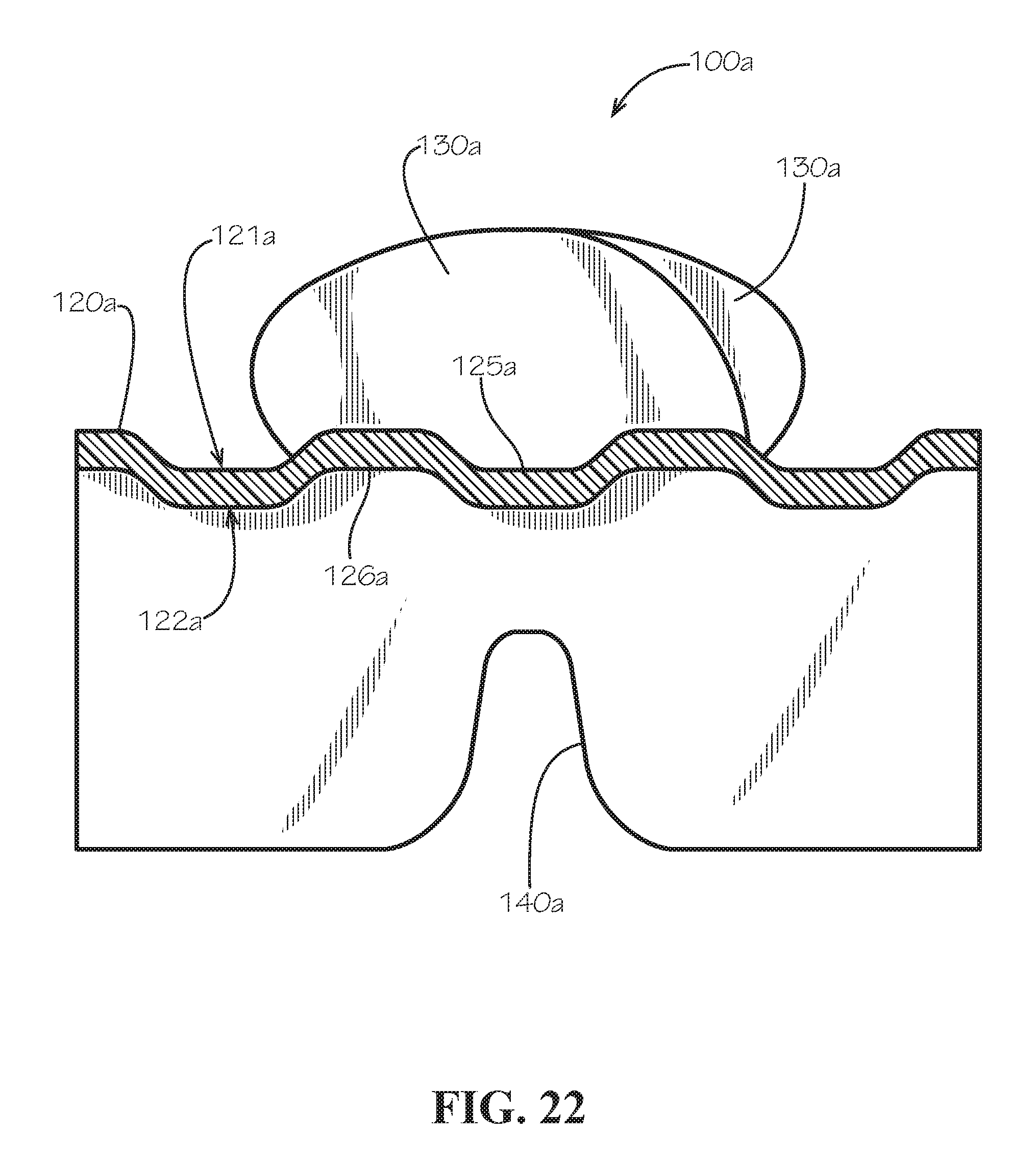
[0030] FIG. 22 is a sectional view of the first fastening device of FIG. 21 taken along line 22-22 of FIG. 21.
[0031] FIG. 23 is a perspective view of the first fastening device of FIG. 1 comprising a composite tape portion in accordance with another aspect of the current disclosure.
DETAILED DESCRIPTION
[0032] The present disclosure can be understood more readily by reference to the following detailed description, examples, drawings, and claims, and their previous and following description. However, before the present devices, systems, and/or methods are disclosed and described, it is to be understood that this disclosure is not limited to the specific devices, systems, and/or methods disclosed unless otherwise specified, as such can, of course, vary. It is also to be understood that the terminology used herein is for the purpose of describing particular aspects only and is not intended to be limiting.
[0033] The following description is provided as an enabling teaching of the present devices, systems, and/or methods in their best, currently known aspect. To this end, those skilled in the relevant art will recognize and appreciate that many changes can be made to the various aspects described herein, while still obtaining the beneficial results of the present disclosure. It will also be apparent that some of the desired benefits of the present disclosure can be obtained by selecting some of the features of the present disclosure without utilizing other features. Accordingly, those who work in the art will recognize that many modifications and adaptations to the present disclosure are possible and can even be desirable in certain circumstances and are a part of the present disclosure. Thus, the following description is provided as illustrative of the principles of the present disclosure and not in limitation thereof.
[0034] As used throughout, the singular forms "a," "an" and "the" include plural referents unless the context clearly dictates otherwise. Thus, for example, reference to a quantity of one of a particular element can comprise two or more such elements unless the context indicates otherwise.
[0035] Ranges can be expressed herein as from "about" one particular value, and/or to "about" another particular value. When such a range is expressed, another aspect comprises from the one particular value and/or to the other particular value. Similarly, when values are expressed as approximations, by use of the antecedent "about" or "substantially," it will be understood that the particular value forms another aspect. It will be further understood that the endpoints of each of the ranges are significant both in relation to the other endpoint, and independently of the other endpoint.
[0036] For purposes of the current disclosure, a material property or dimension measuring about X or substantially X on a particular measurement scale measures within a range between X plus an industry-standard upper tolerance for the specified measurement and X minus an industry-standard lower tolerance for the specified measurement. Because tolerances can vary between different materials, processes and between different models, the tolerance for a particular measurement of a particular component can fall within a range of tolerances.
[0037] As used herein, the terms "optional" or "optionally" mean that the subsequently described event or circumstance may or may not occur, and that the description comprises instances where said event or circumstance occurs and instances where it does not.
[0038] The word "or" as used herein means any one member of a particular list and also comprises any combination of members of that list.
[0039] To simplify the description of various elements disclosed herein, the conventions of "left," "right," "front," "rear," "top," "bottom," "upper," "lower," "inside," "outside," "inboard," "outboard," "horizontal," and/or "vertical" may be referenced. Unless stated otherwise, "front" describes that end of the fastening system nearest to a first longitudinal or lengthwise end of the fastening system; "rear" is that end of the seat that is opposite or distal the front; "left" is that which is to the left of or facing left while facing towards the front; and "right" is that which is to the right of or facing right while facing towards the front. "Horizontal" or "horizontal orientation" describes that which is in a plane extending from left to right and aligned with the horizon. "Vertical" or "vertical orientation" describes that which is in a plane that is angled at 90 degrees to the horizontal.
[0040] In various aspects, a fastening system and associated methods, systems, devices, and various apparatuses are disclosed herein. In some aspects, the fastening system can comprise a pair of fastening devices comprising a fastening portion and a tape portion.
[0041] FIG. 1 discloses a fastening system 90. The fastening system 90 can comprise a first fastening device 100a and a second fastening device 100b. Each of the fastening devices 100a,b can comprise a respective fastening portion 110a,b and a respective tape portion 120a,b joined to the fastening portion 110a,b.
[0042] Each of the fastening portions 110a,b can comprise a respective base 115a,b defining a respective first side surface 111a,b (111b shown in FIG. 2) and a respective second side surface 112a,b (112a shown in FIG. 2) opposite from the first side surface 111a,b. Likewise, each of the tape portions 120a,b can define a respective first side surface 121a,b (121b shown in FIG. 4) and a respective second side surface 122a,b (122a shown in FIG. 3) opposite from the first side surface 121a,b.
[0043] Each of the fastening portions 110a,b can comprise a plurality of respective fastening elements 130a,b extending from the respective first side surface 111a,b of the respective fastening portion 110a,b. More specifically, each of the plurality of fastening elements 130a,b can be arranged lengthwise along a respective lengthwise direction 103a,b of the respective fastening device 100a,b, where each lengthwise direction 103a,b generally runs parallel with a respective outer edge 105a,b (105a shown in FIG. 3) of the fastening device 100a,b and is angled at 90 degrees with respect to a respective transverse direction 104a,b of each fastening device 100a,b.
[0044] As shown in FIG. 2, taken from a line 2-2 that goes through a row of fastening elements adjacent to the intermediate wall 320a shown, e.g., in FIG. 3, each adjacent pair of fastening elements 130a,b--i.e., each pair of fastening elements 130a,b positioned adjacent each other in the lengthwise direction 103a,b--can be offset by a fastening element pitch distance 118. Each adjacent pair of fastening elements 130a,b can define a fastening gap 116a,b therebetween. The second fastening portion 110b of the second fastening device 100b can be configured to fasten to the first fastening portion 110a of the first fastening device 100a, including when the first side surface 111b of the second fastening portion 110b is facing the first side surface 111a of the first fastening portion 110a. Specifically, the plurality of fastening gaps 116a of the first fastening portion 110a can be sized to lockably receive the plurality of fastening elements 130b of the second fastening portion 110b; and the plurality of fastening gaps 116b of the second fastening portion 110b can be sized to lockably receive the plurality of fastening elements 130a of the first fastening portion 110a. Together, the assembled first fastening device 100a and the second fastening device 100b can define a total assembled thickness 210.
[0045] The second side surface 112a,b of each of the fastening portions 110a,b can define a plurality of relief grooves 140a,b (140a shown in FIG. 2). The plurality of relief grooves 140a,b can be defined in the respective fastening portion 110a,b in a position that is substantially aligned in the lengthwise direction 103a,b of the respective fastening device 100a,b with the fastening element 130a,b of the fastening portion 110a,b of the fastening device 100a,b. When "substantially aligned," each relief groove 140a,b is defined in any lengthwise portion of the base 115a,b of the fastening portion 110a,b from which the fastening elements 130a,b extend. When "aligned," a center of each of the relief grooves 140a,b is aligned at least substantially with a center of each of the fastening elements 130a,b. Each adjacent pair of relief grooves 140a,b can be offset by a relief groove pitch distance 119. Each of the relief grooves 140a,b can extend across the fastening portion in the transverse direction 104a,b.
[0046] In some aspects, as shown, the plurality of fastening elements 130a of the first fastening device 100a can be formed monolithically with each other. Likewise, the plurality of fastening elements 130b of the second fastening device 100b can be formed monolithically with each other. In other aspects, the plurality of fastening elements 130a of the first fastening device 100a can be formed monolithically with the first tape portion 120a. Likewise, the plurality of fastening elements 130b of the second fastening device 100b can be formed monolithically with the second tape portion. 120b. In yet other aspects, the fastening portion 110a,b can be formed separately from the tape portion 120a,b and later joined to the tape portion 120a,b.
[0047] As shown in FIG. 3, the first fastening device 100a can define a transverse centerline 304a that is parallel to the transverse direction 104a and extends in a plane positioned halfway between the first side surface 121a and the second side surface 122a of the first tape portion 120a. Likewise, the second fastening device 100b can define a transverse centerline 304b (shown in FIG. 4) that is parallel to the transverse direction 104b and extends in a plane positioned halfway between the first side surface 121b and the second side surface 122b of the second tape portion 120b. In some aspects as will be discussed with respect to point symmetry, the first fastening device 100a is also representative of the second fastening device 100b.
[0048] Each of the fastening devices 100a,b can further comprise an inner wall 310a,b (310b shown in FIG. 4) joining the base 115a,b to the tape portion 120a,b, an outer wall 330a,b (330b shown in FIG. 4) distal from the inner wall 310a,b, and an intermediate wall 320a,b (320b shown in FIG. 4) positioned between the inner wall 310a,b and the outer wall 330a,b. In some aspects, as shown in FIG. 3, the intermediate wall 320a can extend from the base 115a and terminate at the transverse centerline 304a. In other aspects, as shown in FIG. 4, the intermediate wall 320a can terminate short of the transverse centerline 304a and respective intermediate walls 320a,b can define an intermediate wall gap 327 (shown in FIG. 4) therebetween when the fastening devices 100a,b are joined to each other. With the presence of the aforementioned walls (e.g., the inner wall 310a,b, the outer wall 330a,b, and the intermediate wall 320a,b), the cross-wise strength of the fastening devices 100a,b against any load on the tape portions 120a,b in the transverse direction 104a,b can be improved, i.e., the likelihood of disengagement of the fastening devices 100a,b in the transverse direction 104a,b can be reduced.
[0049] In some aspects, as shown, a first row 331a,b (331b shown in FIG. 4) of fastener elements 130a,b and a second row 332a,b (332b shown in FIG. 4) of fastener elements 130a,b can be positioned on either side of the respective intermediate wall 320a,b. The fastener devices 100a,b can further comprise a third row 333a,b (333b shown in FIG. 4) of the fastening elements 130a,b and a fourth row 334a,b (334b shown in FIG. 4) of the fastening elements 130a,b. Any two of the first row 331a,b, the second row 332a,b, the third row 333a,b, and the fourth row 334a,b of the fastening elements 130a,b can be aligned in the lengthwise direction 103a,b of the fastening device 100a,b and positioned parallel to each other. The third row 333a,b of the fastening elements 130a,b can be substantially aligned in the lengthwise direction 103a,b of the fastening devices 100a,b and positioned adjacent to and offset from the first row 331a,b of the fastening elements 130a,b of the respective fastening device 100a,b in a direction extending away from the second row 332a,b of the fastening elements 130a,b, and the fourth row 334a,b of the fastening elements 130a,b can be substantially aligned in the lengthwise direction 103a,b of the fastening devices 100a,b and positioned adjacent to and offset from the second row 332a,b of the fastening elements 130a,b of the fastening device 100a,b in a direction extending away from the first row 331a,b of the fastening elements 130a,b.
[0050] As shown, each fastening element 130a,b of the first row 331a,b, the second row 332a,b, the third row 333a,b and the fourth row 334a,b can be offset from any neighboring wall--e.g., the inner wall 310a, the intermediate wall 320a, or the outer wall 330a,b--by a lateral gap distance 317. For example and without limitation, the first row 331a,b of the fastening elements 130a,b and the intermediate wall 320a,b can define a lateral gap distance 317, and likewise the first row 331a,b of the fastening elements 130a,b and the third row 333a,b can define a lateral gap distance 317. While the presence of any of the inner wall 310a, the intermediate wall 320a, or the outer wall 330a,b can restrict movement of the second fastening device 100b with respect to the first fastening device 100a, the lateral gap distance 317 can help decrease the need for the accurate alignment of the first fastening device 100a and the second fastening device 100b in the transverse directions 104a,b.
[0051] In some aspects, as shown in FIG. 4, the first tape portion 120a and the second tape portion 120b can be made substantially coplanar when the fastening portions 110a,b are engaged to each other. More specifically, the transverse centerline 304a of the first tape portion 120a can be made at least substantially coplanar with the transverse centerline 304b of the second tape portion 120b. With this coplanar orientation or arrangement, bending of the fastening system 90 as shown in FIGS. 6 and 8 and application of any load on the tape portions 120a,b in the transverse direction 104a,b is less likely to cause non-uniform bending of the fastening system 90 or twisting of the connection between the fastening devices 120a,b. More specifically, a longitudinal centerline 604 (shown in FIGS. 6 and 8) of the bent joint of the fastening system 90 can in the process be made coincident or coplanar with the transverse centerlines 304a,b.
[0052] In some aspects, as shown in FIG. 5, each fastening element 130a,b of the fastening device 100a,b can comprise an engagement portion 133a,b and an engagement portion 134a,b extending in a direction parallel to the lengthwise direction 103a,b of the fastening device 100a,b. In some aspects, each of the engagement portions 133a,b,134a,b can comprise a hook, as shown in FIGS. 5 and 7. A hook is any shape extending in a specified direction (in the aforementioned aspect, the lengthwise direction 103a,b) that either extends past a portion of a base of the corresponding fastening element 130a,b in the specified direction such that the hook would tend to catch on the hook of a mating fastener device or is otherwise configured to catch on a mating fastener device. In other aspects, each of the engagement portions 133a,b,134a,b need not comprise a hook. Extension of the fastening element 130a,b past the base of the fastening element 130a,b to create the engagement portion 133a,b or the engagement portion 134a,b can create an undercut or relief between the engagement portion 133a,b,134a,b and the base 115a,b as shown that, among other unique features of the fastening system 90, can be molded through various exemplary methods as will be described. As shown, the fastening element 130a,b can be made symmetric about a protrusional centerline 530a,b of the fastening element 130a,b. In some aspects, as shown, the fastening device 100a,b need not define the aforementioned relief groove 140a,b. In other aspects, the fastening device 100a,b can comprise a plurality of fastening elements 130a,b having symmetry about the protrusional centerline 530a,b, each defining the relief groove 140a,b and exhibiting the same level of flexibility shown below with fastening elements 130a,b having an asymmetric shape.
[0053] As shown in FIG. 6, when the first fastening device 100a is joined to the second fastening device 100b and the resulting fastening system 90 is bent as shown, interference between the fastening elements 130a,b prevents bending of the fastening system 90 below a minimum bend radius 610. As shown, even when each of the fastening devices 100a,b is formed from a resilient or flexible material, the rigidity of each segment of the fastening devices 100a,b restricts the flexibility of the assembled fastening system 90, where each segment can comprise a single fastening element 130a,b extending in the lengthwise direction 103a,b. Even relatively slight bending of the fastening system 90 causes misalignment between each of the protrusional centerlines 530a,b and a corresponding centerline 616a,b of each fastening gap 116a,b.
[0054] In other aspects, as shown in FIG. 7, each fastening element 130a,b of the fastening device 100a,b can be made asymmetric about the protrusional centerline 530a,b of the fastening element 130a,b. In some aspects, as shown, each fastening device 100a,b can define the aforementioned relief groove 140a,b proximate to each fastening element 130a,b. The relief groove 140a,b can define a tapered opening when viewed in cross-section along the transverse direction 104a,b. The tapered opening of the relief groove 140a,b can define an open angle 710a,b.
[0055] As shown in FIG. 8, when the first fastening device 100a is joined to the second fastening device 100b and the resulting fastening system 90 is bent as shown, bending to the bend radius 610 is not limited by interference between the fastening elements 130a,b. As shown, especially when each of the fastening devices 100a,b is formed from a resilient or flexible material, the flexibility of each segment of the fastening devices 100a,b makes it possible to maintain alignment between each of the protrusional centerlines 530a,b and the corresponding centerline 616a,b of each fastening gap 116a,b. For example, as shown, the open angle 710b of each of the relief grooves 140b of the second fastening device 100b can open up or increase as needed, and likewise the open angle 710a of each of the relief grooves 140a of the first fastening device 100a can close up or decrease as needed--even to a negative value until each of the relief grooves 140a closes completely on itself. Accordingly, the geometry of each of the relieve grooves 140a,b can be adjusted to allow for more or less bending of the fastening system 90 without disengagement of the fastening devices 100a,b from each other. Disengagement of the fastening devices 100a,b from each other can be a consequence of a fastening system that is not configured to be bent to the desired bend radius 610, at least when the force to overcome the interference between mating engagement portions 133a,b is less than the force to deform the engagement portions 133a,b or other portions of the fastening devices 100a,b, which itself can lead to accelerated disengagement.
[0056] The engagement portions 133a,b can be arranged in more than one direction or orientation on a fastening device 100a,b. As shown in the fastening system 90 of FIG. 8, an inner row (i.e., the row shown in cross-section) can extend to the right as shown, and an outer row can extend to the left. As shown in the fastening system 90 of FIG. 2, the directions in which the inner and outer rows extend can be reversed. When incorporated into the fastening system 90, the aforementioned asymmetry or symmetry of the fastening elements 130a,b about the corresponding protrusional centerline 530a,b can be used to ensure that two panels to be joined (not shown) can only be assembled in one orientation--for example and without limitation, when the orientation of the mating fastening devices is in matching alignment. As will be described, however, it is also possible for a fastening device exhibiting "point symmetry" to be assembled in more than one orientation.
[0057] As shown in FIG. 9, the first row 331a of the fastening elements 130a and the second row 332a of the fastening elements 130a can comprise the engagement portion 133a, and each of the engagement portions 133a can be made to extend in the same lengthwise direction 103a. Additionally, a fastening device such as the first fastening device 100a need not include the outer wall 330a. In some aspects, as shown, each fastening element 130a in the first row 331a is aligned in the same position along the lengthwise direction 103a as a neighboring fastening element 130a in the second row 332a. In other aspects, as shown and in any other aspect comprising more than one row such as the first row 331a, one or more fastening elements 130a in the first row 331a can be offset in the lengthwise direction 103a from the closest neighboring fastening element 130a in the second row 332a.
[0058] As shown in FIG. 10, each of the engagement portions 133a of the fastening elements 130a of the first row 331a, the second row 332a, the third row 333a, and the fourth row 334a can be made to extend in the same lengthwise direction 103a.
[0059] As shown in FIG. 11, the first fastening device 100a can comprise only a single row of fastening elements 130a bounded by the inner wall 310a and the outer wall 330a.
[0060] In some aspects, as shown in FIG. 12, similarly to that shown in FIG. 1, the engagement portions 133a of the fastening elements 130a in adjacent rows of the fastening elements 130a can be made to extend in opposite directions along the lengthwise direction 103a. In other aspects, the engagement portions 133a,b can extend in a direction that is angled with respect to, but not necessarily in an opposite direction from, the direction in which the engagement portions 133a,b of the plurality of the fastening elements 130a,b in the first row 331a.b of the fastening elements 130a,b of the respective fastening device 100a,b extend. Fastening devices 100a,b comprising rows of fastening elements with engagement portions extending in more than one direction can improve engagement strength and can also improve crosswise strength due to the geometry of the engagement portions 133a,b extending in one direction interfering with the geometry of the engagement portions 133a,b extending in another direction.
[0061] Each of the fastening devices 100a,b can comprise any number of rows. For example and without limitation, a fastening portion 110a of the fastening device 100a can comprise six rows or more of the fastening elements 130a. Increasing the number of rows can likewise improve engagement strength and crosswise strength.
[0062] In other aspects, as shown in FIGS. 13 and 14, a wall of the fastening device 100a such as, for example and without limitation, the intermediate wall 320a can be segmented instead of continuous. A wall 320a that is "segmented" defines breaks or wall gaps 340a,b (340b not shown) at which points the wall 320a is reduced in height or disappears and can define a segmented wall pitch 1318 offsetting the segments of the wall 320a from one another. A segmented wall can further increase the flexibility of the fastening portion 110a,b of the fastening device 100a,b. In some aspects, the segmented wall pitch 1318 can be different than the fastening element pitch distance 118. In other aspects, the segmented wall pitch 310 can equal the fastening element pitch distance 118 or the relief groove pitch distance 119.
[0063] As shown in FIGS. 15-17, a wall such as the intermediate wall 320a of the fastening portion 110a can comprise a seal 1410a. The seal 1410a can be configured to create a compressible and watertight seal against the second fastening device 100b during assembly of the second fastening device 100b with the first fastening device 100a. For example and without limitation, a height of the seal 1410a can be made higher than the space available for the seal 1410a in the assembled fastening system 90. Additionally, the seal 1410a can be made from a material having a lower durometer (i.e., hardness) such that the material compresses under the pressures experienced during assembly of the fastening devices 110a,b. As shown in FIG. 15, the seal 1410a can extend the length of the intermediate wall 320a. In some aspects, as shown in FIGS. 16 and 17, the intermediate wall 320b of the second fastening device 100a can comprise a seal 1410b to seal against the seal 1410a of the first fastening device 100a. In other aspects, only one of the intermediate walls 320a,b comprises the seal 1410a or the seal 1410b, in which case the seal 1410a or the seal 1410b that is present can seal against the intermediate wall 320b or the intermediate wall 320a, respectively. In other aspects not shown, either or both of the inner wall 310a,b or the outer wall 330a,b of the respective fastening device 100a,b can comprise a seal.
[0064] In some aspects, as shown, the seal can have a semicircular shape in cross-section that can progressively resist compression due to the increasingly larger sealing surface area during the compression process. In other aspects, the seal 1410a,b can have a rectangular shape in cross-section. In yet other aspects, the seal 1410a,b can have any other desirable shape including, for example and without limitation, a triangular shape. In some aspects, the seal 1410a,b can have a solid cross-section. In other aspects, the seal 1410a,b can be hollow. In some aspects, as shown, the seals 1410a,b can be symmetrical about the centerline 304a and can oppose one another. A watertight seal between the seals 1410a,b can thereby be effectuated by a compression force acting on each of the seals 1410a,b in the same direction in which they come together (i.e., towards the respective first side surface 111a,b of each fastening portion 110a,b or in a direction that is normal to the respective first side surface 111a,b). In other aspects, the seals 1410a,b can be offset such that the seal 1410b slides past the seal 1410a during engagement of the fastening portion 110b with the fastening portion 110a. A side surface of each of the seals 1410a,b can thereby face each other and seal against one another. A watertight seal between the seals 1410a,b can thereby be effectuated by a compression force acting at least partly on the side surface of each of the seals 1410a,b in the transverse directions 104a,b (shown in FIG. 4). In yet other aspects, one or both seals 1410a,b can comprise facing angled or tapered surfaces that meet and seal during engagement of the fastening portion 110b with the fastening portion 110a. Again, a side surface of each of the seals 1410a,b can thereby face each other and seal against one another. A watertight seal between the seals 1410a,b can also thereby be effectuated by a component of a compression force acting on the side surface of each of the seals 1410a,b in the transverse directions 104a,b and a component of a compression force acting on the side surface of each of the seals 1410a,b in a direction that is normal to the respective first side surface 111a,b.
[0065] As shown in FIG. 18, when the fastening elements 130a,b of the fastening portion 110a,b are arranged in "point symmetry" or symmetric about a point 1810, it is possible to engage the two fastening devices 100a,b, at least as long as the mating portions of the fastening portions 110a,b have the same shape. In other words, through point symmetry the first fastening device can be configured to be joined to a second fastening device comprising a second fastening portion having the same geometry as the first fastening portion of the first fastening device. When point symmetry exists, laterally adjacent fastening elements 130a (i.e., fastening elements 130a that are adjacent to each other in the transverse direction 104a,b of the first fastening portion) are symmetric about a point positioned halfway between the laterally adjacent fastening elements. More specifically, when point symmetry exists every structural element has a matching structural element that is the same distance from the central point 1810 but in the opposite direction. In some aspects, the fastening portion 110a,b can be described as radially symmetric about an axis extending through the point 1810 such that one fastening element 130a can be rotated 180 degrees about the axis/point 1810 and will overlay another fastening element 130a. In addition, with either point symmetry or radially symmetry it is possible to engage the two fastening devices 100a,b in two different orientations. In some aspects, as shown in FIGS. 1 and 20, the first tape portion 120a can be made to extend in a first transverse direction parallel to the transverse direction 104a and the second tape portion 120b can be made to extend in a second transverse direction that is opposite the first transverse direction.
[0066] Each fastening element 130a,b can define an element width 1710 (shown in FIG. 17). In some aspects, the element width 1710 of fastening elements of each row such as the rows 331a,b,332a,b,333a,b,334a,b can be the same. In other aspects, the element width 1710 can vary between rows or between fastening elements 130a,b and the fastening device 100a,b still exhibit point symmetry or radial symmetry.
[0067] As shown in FIG. 19, in a fastening system 90 exhibiting point symmetry, both the first tape portion 120a and the second tape portion 120b can be made to extend in the same transverse direction 104a. In the fastening system 90 shown in FIG. 19, the fastening devices 100a,b can be engaged with each other using fingers and without a slider because one can access and therefore apply pressure more easily to the second side 112a,b of both the first fastening device 100a and the second fastening device 100b at the same time. As shown in FIG. 20, the fastening system 90 can comprise a slider 1910. The slider 1910 in a different configuration can be used with the fastening system 90 shown in FIG. 19 as well. The slider 1910 can, for example and without limitation, also comprise a pull tab or other structure for ergonomic operation. The slider 1910 can be simultaneously coupled to both the first fastening device 100a and the second fastening device 100b and be configured to selectively engage and disengage the second fastening device 100b from the first fastening device 100a, or vice versa.
[0068] As shown in FIGS. 21 and 22, a tape portion such as the first tape portion 120a can be formed into a wave pattern in cross-section. With a tape portion 120a,b defining such a wave pattern, both the first side surface 121a and the second side surface 122a can define undulations 125a,126a, respectively, that can provide extra flexibility in the tape portion 120a,b and as a result make it possible to minimize the bend radius 610 (shown in FIG. 8) with both fastening devices 100a,b and with the assembled fastening system 90. Each of the undulations 125a,126a can be a recess in the first side surface 121a and the second side surface 122a, respectively.
[0069] As shown in FIG. 23, an auxiliary tape 2210 can be secured to the first tape portion 120a by a process such as, for example and without limitation, insert extrusion, co-extrusion, welding, adhesion, sewing, or another chemical or mechanical joining method. In some aspects, the auxiliary tape 2210 itself can comprise a woven or non-woven fabric material. In other aspects, the auxiliary tape can be any other material including a metal, plastic or composite material sufficiently able to flex with the fastening devices 100a,b as desired.
[0070] Various methods exist for manufacturing the fastening devices 100a,b or components thereof, including those shown in U.S. Pat. No. 6,896,759 to Fujisawa, et al., which is hereby incorporated by reference in its entirety. In the processes disclosed therein (e.g., the processes using an extruding die wheel as shown in FIGS. 23, 25, 27, 29A, 29B, 32A, and 33), each of the fastening devices 100a,b can be quickly cooled after molding the fastening elements 130a,b but before removing the fastening elements 130a,b from the dies so as to avoid deformation of the fastening elements 130a,b while the material used to form the fastening devices 100a,b is still warm.
[0071] In some aspects, features formed from different materials, such as the seals 1410a,b formed from a resilient rubber or rubber-like material and the fastening devices 100a,b formed from a flexible but less resilient plastic resin, can be incorporated into the fastening devices using a process such as insert molding or co-extrusion. In other aspects, such features can be incorporated into the fastening devices 100a,b using welding, adhesion, or another chemical or mechanical joining method.
[0072] A method of using the fastening system 90 can comprise obtaining the first fastening device 100a and the second fastening device 100b. The method can further comprise fastening the second fastening portion 110b of the second fastening device 100b to the first fastening portion 110a of the first fastening device 100a when the first side surface 111a of the second fastening portion 110b is facing the first side surface of the first fastening portion 110a. The method can further comprise bending the fastening system 90 to decrease the bend radius 610 of the fastening system. In some aspects, the minimum bend radius 610 of the fastening system 90 can be adjusted by changing the shape and dimensions of the relieve grooves 140a,b.
[0073] One should note that conditional language, such as, among others, "can," "could," "might," or "may," unless specifically stated otherwise, or otherwise understood within the context as used, is generally intended to convey that certain aspects include, while other aspects do not include, certain features, elements and/or steps. Thus, such conditional language is not generally intended to imply that features, elements and/or steps are in any way required for one or more particular aspects or that one or more particular aspects necessarily comprise logic for deciding, with or without user input or prompting, whether these features, elements and/or steps are included or are to be performed in any particular aspect.
[0074] It should be emphasized that the above-described aspects are merely possible examples of implementations, merely set forth for a clear understanding of the principles of the present disclosure. Any process descriptions or blocks in flow diagrams should be understood as representing modules, segments, or portions of code which comprise one or more executable instructions for implementing specific logical functions or steps in the process, and alternate implementations are included in which functions may not be included or executed at all, may be executed out of order from that shown or discussed, including substantially concurrently or in reverse order, depending on the functionality involved, as would be understood by those reasonably skilled in the art of the present disclosure. Many variations and modifications may be made to the above-described aspect(s) without departing substantially from the spirit and principles of the present disclosure. Further, the scope of the present disclosure is intended to cover any and all combinations and sub-combinations of all elements, features, and aspects discussed above. All such modifications and variations are intended to be included herein within the scope of the present disclosure, and all possible claims to individual aspects or combinations of elements or steps are intended to be supported by the present disclosure.
* * * * *
D00000
D00001
D00002
D00003
D00004
D00005
D00006
D00007
D00008
D00009
D00010
D00011
D00012

D00013

D00014

D00015

D00016

D00017

D00018
D00019

XML
uspto.report is an independent third-party trademark research tool that is not affiliated, endorsed, or sponsored by the United States Patent and Trademark Office (USPTO) or any other governmental organization. The information provided by uspto.report is based on publicly available data at the time of writing and is intended for informational purposes only.
While we strive to provide accurate and up-to-date information, we do not guarantee the accuracy, completeness, reliability, or suitability of the information displayed on this site. The use of this site is at your own risk. Any reliance you place on such information is therefore strictly at your own risk.
All official trademark data, including owner information, should be verified by visiting the official USPTO website at www.uspto.gov. This site is not intended to replace professional legal advice and should not be used as a substitute for consulting with a legal professional who is knowledgeable about trademark law.