Method And System For Automated Adjustment Of Drilling Mud Properties
ASTRID; Patricia ; et al.
U.S. patent application number 16/071976 was filed with the patent office on 2019-02-21 for method and system for automated adjustment of drilling mud properties. This patent application is currently assigned to SHELL OIL COMPANY. The applicant listed for this patent is SHELL OIL COMPANY. Invention is credited to Patricia ASTRID, Jan-Jette BLANGE, Svetlana Viktorovna HAGERAATS-PONOMAREVA, Timothy Engelbertus SCHUIT.
| Application Number | 20190055797 16/071976 |
| Document ID | / |
| Family ID | 55229605 |
| Filed Date | 2019-02-21 |
| United States Patent Application | 20190055797 |
| Kind Code | A1 |
| ASTRID; Patricia ; et al. | February 21, 2019 |
METHOD AND SYSTEM FOR AUTOMATED ADJUSTMENT OF DRILLING MUD PROPERTIES
Abstract
Drilling mud properties in a mud recirculation system (13) of an oil and/or gas well drilling assembly (1) are automatically adjusted by an automated mud treating assembly (20,25) that is governed hierarchal primary and secondary optimization and control loops (30,31) that continuously keep the density, viscosity, pH and other mud properties within specifications set by a model-based tertiary optimization and control loop to ensure that the mud properties will lead to sufficient drilled cutting transport, borehole stability, drill bit hydraulics, and minimum friction torque and drag.
| Inventors: | ASTRID; Patricia; (Amsterdam, NL) ; BLANGE; Jan-Jette; (Rijswijk, NL) ; HAGERAATS-PONOMAREVA; Svetlana Viktorovna; (Rijswijk, NL) ; SCHUIT; Timothy Engelbertus; (Rijswijk, NL) | ||||||||||
| Applicant: |
|
||||||||||
|---|---|---|---|---|---|---|---|---|---|---|---|
| Assignee: | SHELL OIL COMPANY HOUSTON TX |
||||||||||
| Family ID: | 55229605 | ||||||||||
| Appl. No.: | 16/071976 | ||||||||||
| Filed: | January 23, 2017 | ||||||||||
| PCT Filed: | January 23, 2017 | ||||||||||
| PCT NO: | PCT/EP2017/051329 | ||||||||||
| 371 Date: | July 23, 2018 |
| Current U.S. Class: | 1/1 |
| Current CPC Class: | E21B 44/00 20130101; E21B 21/106 20130101; E21B 21/062 20130101; E21B 49/0875 20200501; E21B 21/06 20130101; E21B 21/08 20130101 |
| International Class: | E21B 21/06 20060101 E21B021/06; E21B 21/10 20060101 E21B021/10; E21B 21/08 20060101 E21B021/08 |
Foreign Application Data
| Date | Code | Application Number |
|---|---|---|
| Jan 25, 2016 | EP | 16152522.5 |
Claims
1. A method for automated adjustment of drilling mud properties in a mud recirculation system of a rig for drilling an underground wellbore, the method comprising inducing hierarchal primary and secondary optimization and control loops to adjust injection rates of mud additives into a circulated mud stream flowing through an automated mud treating assembly, to continuously keep mud properties, comprising density, viscosity, pH and optionally other mud properties, within specifications set by a model-based tertiary optimization and control loop.
2. The method of claim 1, wherein the primary optimization and control loop governs opening and closing of additive injection control valves of the automated mud treating assembly to meet injection rates of each additive set by set by the secondary optimization and control loop that is connected to the tertiary optimization and control loop that determines the appropriate ranges or setpoints for the mud properties in order to meet multiple operational objectives, such as maximizing cutting transport capabilities of the drilling mud and maintaining wellbore mechanical stability.
3. The method of claim 1, wherein the mud properties are measured by a sensor assembly that measures the mud properties of the mud in the mud recirculation system at the rig upstream and/or downstream of the automated mud treating assembly.
4. The method of claim 3, wherein the sensor assembly comprises an upstream sensor assembly comprising primary and secondary untreated mud flux property sensors for monitoring the properties of the untreated mud flowing from a cuttings removal system to the automated mud treating assembly, wherein the primary untreated mud flux property sensor is arranged in the mud recirculation system between the secondary untreated mud flux property sensor and the mud treating assembly.
5. The method of claim 1, wherein: the primary, secondary and tertiary optimization and control loops operate at different time scales and hierarchies; the tertiary optimization and control loop is the master of the secondary optimization and control loop and operates at the highest time scale or lower sampling rate; and the secondary optimization and control loop is governed by the tertiary optimization and control loop and operates at the lower time scale or higher sampling rate than the tertiary optimization and control loop but higher time scale and lower sampling rate than the primary optimization and control loop which is governed by the secondary optimization and control loop.
6. The method of claim 4, wherein the sensor assembly further comprises a downstream sensor assembly comprising primary and secondary treated mud property sensors for measuring at least one of the group consisting of: density, viscosity, pH and other properties,. of the treated mud in the mud recirculation system at the rig downstream of the mud treating assembly, wherein the primary treated mud flux property sensor is arranged in the mud recirculation system between the mud treating assembly and the secondary treated mud property sensor; and wherein: the primary optimization and control loop is connected to a sensor assembly that measures the actual injection rate of each additive in the automated mud treating assembly; the secondary optimization and control loop is connected to the sensor assembly that measures the primary untreated and treated mud properties; the tertiary optimization and control loop is connected to the primary untreated mud sensor assembly and optionally to the secondary untreated mud sensor assembly.
7. The method of claim 4, wherein the primary treated mud flux property sensor forms part of the secondary optimization and control loop and the secondary treated mud flux property sensor forms part of the tertiary optimization and control loop.
8. The method of claim 1, wherein the tertiary optimization and control loop comprises an optimization module that determines the ranges or the setpoints of the primary treated mud properties given the objective functions of the tertiary optimization and control loop such as ensuring sufficient cutting transport, wellbore mechanical stability and estimates of: a) drill string torque and drag; b) borehole stability and permeability; c) size, volume, weight, density and composition of drill cuttings; and d) downhole mud velocity, pH, viscosity, density and composition.
9. The method of claim 8, wherein the ranges of the mud property values as determined by the optimization module are included as the desired ranges to be honored by a multivariable control algorithm in the secondary control loop.
10. The method of claim 9, wherein the multivariable control algorithm is a Model Predictive Controller (MPC) algorithm that casts the multivariable control problem as an optimal control problem with an objective function of minimizing the deviation of the primary treated mud properties from the desired ranges given the minimum and maximum amount of additives to be added at each cycle and the models between mud properties to be controlled and additives as well as the drilling and mud flux circulation rates.
11. The method of claim 10, wherein the multivariable control algorithm is provided with models identifying mathematical relationships between the additives, mud properties and measured variations in drilling rates that affect variations in drill cuttings concentration.
12. A system for automated adjustment of drilling mud properties in a mud recirculation system of a rig for drilling an underground wellbore, the system comprising hierarchal primary and secondary optimization and control loops to adjust injection rates of mud additives into a mud circulation conduit in an automated mud treating assembly, arranged to continuously keep mud properties, comprising density, viscosity, pH, within specifications set by a model-based tertiary optimization and control loop.
13. The system of claim 12, wherein the primary optimization and control that governs opening and closing of the additive control valves of the automated mud treating assembly, to meet the injection rates of each additive set by set by the secondary optimization and control loop that is connected to the tertiary optimization and control loop that determines the appropriate ranges or setpoints for the mud properties in order to meet multiple operational objectives, such as maximizing cutting transport capabilities of the drilling mud and maintaining wellbore mechanical stability.
14. The system of claim 12, wherein the system comprises a sensor assembly that measures the mud properties of the mud in the mud recirculation system at the rig upstream and/or downstream of the automated mud treating assembly.
15. The system of claim 12, wherein the mud treating assembly comprises an additives and mud mixing tank, the size of which is determined by two aspects: the minimum residence time required by the characteristics of the drilling mud to ensure a homogeneous mixture when additives are added; and the balance between the response time required by the secondary multivariable control loop to bring the properties of the primary untreated mud to the desired values or ranges while ensuring that the addition of the additives as the result of the controller's actions does not lead to major fluctuations in the steady state or transient values of the primary treated and secondary untreated mud properties.
16. The system of claim 12, wherein said hierarchal primary and secondary optimization and control loops are additionally arranged to continuously keep other mud properties within specifications set by the model-based tertiary optimization and control loop.
17. The method of claim 1, wherein additionally inducing said hierarchal primary and secondary optimization and control loops to continuously keep other mud properties within specifications set by the model-based tertiary optimization and control loop.
Description
FIELD OF THE INVENTION
[0001] The present invention relates to a method and system for automated adjustment of drilling mud properties in a mud recirculation system of a rig for drilling an underground wellbore.
BACKGROUND OF THE INVENTION
[0002] During drilling of underground wellbores for the production of crude oil and/or natural gas a drilling fluid, generally known as drilling mud, is circulated in downward direction through the interior of the drill string and then in upward direction through the surrounding annulus to lift drill cuttings to the surface, to clean and cool the drill bit, to stabilize the borehole, to lubricate the rotating drill string and to provide hydrostatic head for preventing well kicks.
[0003] At the wellhead the drill cuttings are removed from the drilling mud in a mud cleaning assembly and the mud volume is adjusted by adding fresh mud and the composition of the re-injected mud is adjusted by adding mud additives in a mud treatment assembly to generate desired mud properties, such as mud density, viscosity and pH.
[0004] A fluid handling system is described in WO 97/42395 A1, specifically for underbalanced drilling operations. A control unit determines or computes values of a number of operating parameters of the fluid handling system and controls the operation of the various devices based on such parameters according to programs and models provided to the control unit. The control unit, which receives signals from sensors, is coupled to the various devices in the system for controlling the operations of the devices, including control valves. The control unit periodically or continually determines the required drilling fluid mix as a function of one or more of the selected operating parameters and operates a control valve to discharge a correct amount of additive materials to obtain the desired mix.
[0005] At the moment, there is no integrated solution utilizing a combination of integrated hardware and software that makes use of the measurement data to predict the downhole condition and control the mud properties in order to mitigate or avoid operational issues.
[0006] There is a need for an improved mud additive injection control system and method which overcome the drawbacks of the prior art.
[0007] Furthermore there is a need for a more efficient mud system management that minimizes waste and use of materials used to treat the mud and minimize operational downtime, due to for example a stuck drill pipe and/or drill pipe vibration, and operational issues, such as lack of well control and/or borehole instability due to the failure of keeping the mud properties at the desired specification.
SUMMARY OF THE INVENTION
[0008] In one aspect of the invention, there is provided a method for automated adjustment of drilling mud properties in a mud recirculation system of a rig for drilling an underground wellbore, the method comprising inducing hierarchal primary and secondary optimization and control loops to adjust injection rates of mud additives into a circulated mud stream flowing through an automated mud treating assembly, to continuously keep mud properties, comprising density, viscosity, pH and optionally other mud properties, within specifications set by a model-based tertiary optimization and control loop.
[0009] In another aspect of the invention, there is provided a system for automated adjustment of drilling mud properties in a mud recirculation system of a rig for drilling an underground wellbore, the system comprising hierarchal primary and secondary optimization and control loops to adjust injection rates of mud additives into a mud circulation conduit in an automated mud treating assembly, arranged to continuously keep mud properties, comprising density, viscosity, pH and optionally other mud properties, within specifications set a model-based tertiary optimization and control loop.
[0010] These and other features, embodiments and advantages of the method and system as proposed herein are described in the accompanying claims, abstract and the following detailed description of non-limiting embodiments depicted in the accompanying drawing, in which description reference numerals are used which refer to corresponding reference numerals that are depicted in the drawing.
[0011] Objects and other features depicted in the figure and/or described in this specification, abstract and/or claims may be combined in different ways by a person skilled in the art.
BRIEF DESCRIPTION OF THE DRAWING
[0012] The systems and methods will be described hereinafter by way of example in more detail with reference to FIG. 1, which is a schematic representation of a drilling assembly provided with an automated mud additive injection control system. No limitations are intended to the details of construction or design herein shown, other than as described in the claims below.
DETAILED DESCRIPTION OF THE DEPICTED EMBODIMENT
[0013] A method and system are proposed for automated adjustment of drilling mud properties in a mud recirculation system. Such mud recirculation system may form part of a drilling assembly for excavating an underground wellbore. The mud recirculation system may be applied on a rig for drilling an underground formation.
[0014] In one proposed method for automated adjustment of drilling mud properties in a mud recirculation system of a rig for drilling an underground wellbore, hierarchal primary and secondary optimization and control loops are induced to control an automated mud treating assembly which injects additives that continuously keep density, viscosity, pH and other mud properties within the specifications. Rather than that these specifications are set by an operator, a tertiary model-based optimization and control loop may be run to set the specifications.
[0015] This may be implemented by three nested optimization and control loops as follows: the tertiary optimization and control loop determines specifications for mud properties comprising density, viscosity, pH and optionally other mud properties on the basis of a model which optimizes desired downhole properties of the injected mud for assessed downhole drilling conditions. These mud property specifications are fed as setpoints to the secondary optimization and control loop, which determines the required additives to achieve the desired setpoint mud properties. The required additives as computed by the secondary loop then become the setpoints for the primary control loops, which open additive injection valves to achieve the required additives. The tertiary optimization and control loop may also determine setpoints of flow rate of the circulated mud stream, which may be fed directly to the pump control system without intervention by the secondary and primary optimization and control loops.
[0016] The mud properties may be measured by a sensor assembly that measures density, viscosity, pH and/or other properties of the mud in the mud recirculation system at the rig upstream and/or downstream of the automated mud treating assembly, which sensor assembly may comprise an upstream sensor assembly comprising primary and secondary untreated mud property sensors for monitoring the properties of the untreated mud flowing from a cuttings removal system to the automated mud treating assembly. The primary untreated mud flux property sensor may be arranged in the mud recirculation system between the secondary untreated mud flux property sensor and the mud treating assembly.
[0017] The automated mud treating assembly may comprise additive injection control devices, suitably injection control valves, that are controlled by the primary optimization and control loop to meet the injection rates of each additive set by set by the secondary optimization and control loop that is connected to the tertiary optimization and control loop that determines the appropriate ranges or setpoints for density, viscosity, pH and other mud properties in order to meet multiple operational objectives, such as maximizing cutting transport capabilities of the drilling mud and maintaining wellbore mechanical stability.
[0018] Optionally, the primary, secondary and tertiary optimization and control loops operate at different time scales and hierarchies, whereby: [0019] the tertiary optimization and control loop is the master of the secondary optimization and control loop and operates at the highest time scale or lower sampling rate; and [0020] the secondary optimization and control loop is governed by, also called the slave of, the tertiary optimization and control loop and operates at the lower time scale or higher sampling rate than the tertiary optimization and control loop but higher time scale and lower sampling rate than the primary optimization and control loop which is governed by, also called the slave of, the secondary optimization and control loop.
[0021] The tertiary optimization and control loop may comprise an optimization module that determines the ranges or the setpoints of the primary treated mud properties given the objective functions of the tertiary optimization and control loop such as ensuring sufficient cutting transport, wellbore mechanical stability and given estimates of:
[0022] a) drill string torque and drag;
[0023] b) borehole stability and permeability;
[0024] c) size, volume, weight, density and composition of drill cuttings; and
[0025] d) downhole mud velocity, pH, viscosity, density and composition.
[0026] The ranges of the mud property values as determined by the optimization module of the tertiary loop may suitably be included as the desired ranges to be honored by a multivariable control algorithm in the secondary control loop. The multivariable control algorithm suitably provides a setpoint for the injection rate of each one of the injected mud additives. The multivariable control algorithm may be a Model Predictive Controller (MPC) algorithm that casts the multivariable control problem as an optimal control problem with an objective function of minimizing the deviation of the primary treated mud properties from the desired ranges given the minimum and maximum amount of additives to be added at each cycle and the models between mud properties to be controlled and additives as well as the drilling and mud flux circulation rates, which casts the mud properties control problem into a multivariable optimization solution with constraints over a selected time horizon that take into account the amount of time required for the mud to be circulated through the borehole and back to the drilling rig at earth surface.
[0027] The multivariable control MPC algorithm may be provided with models identifying mathematical relationships between the additives, mud properties and measured variations in drilling rates that affect variations in drill cuttings concentration.
[0028] The proposed method may be implemented in a system for automated adjustment of drilling mud properties in the mud recirculation system.
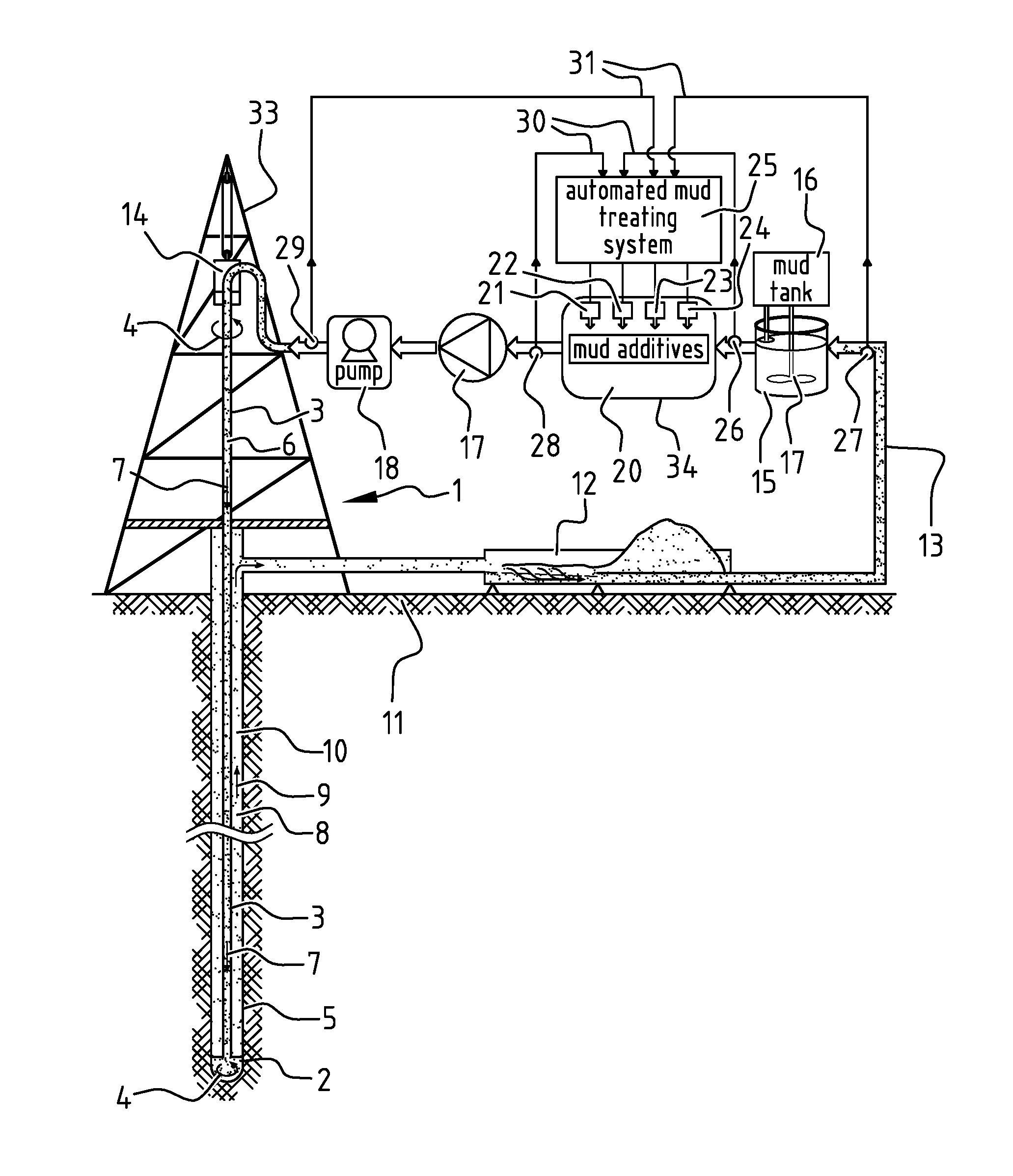
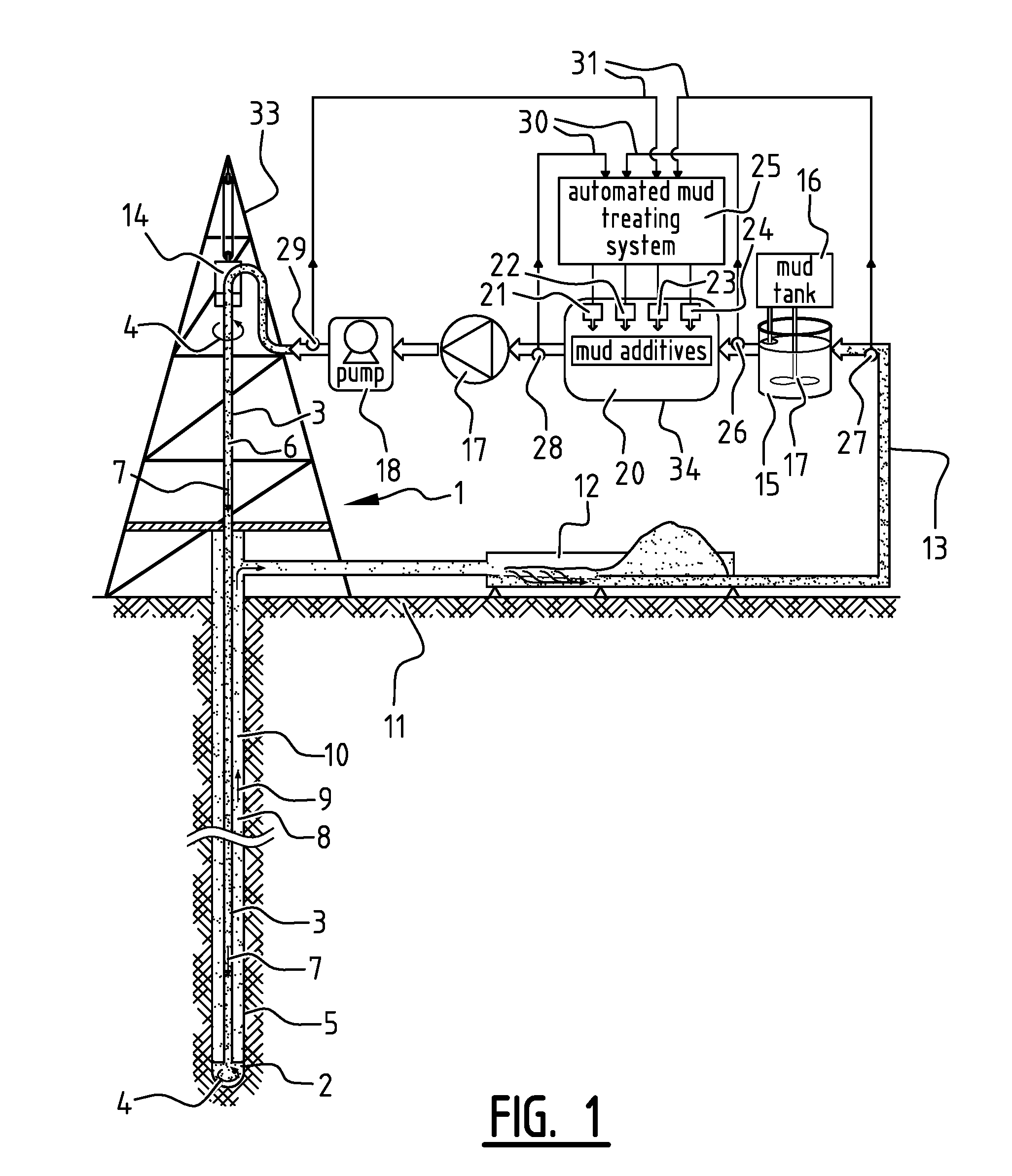
[0029] An example of an implementation of an automated mud treatment system and method is illustrated with reference to FIG. 1. FIG. 1 shows a drilling assembly 1 comprising a drill bit 2 that is rotated by a drill string 3 as illustrated by arrows 4 to excavate an underground borehole 5.
[0030] Drilling mud 6 is pumped down through the drill string 3 as illustrated by arrows 7 and up through the surrounding annulus 8 as illustrated by arrow 9 to lift drill cuttings 10 to the earth surface 11, where the drill cuttings are removed from the returned mud 6 in a mud shaker and filter assembly 12.
[0031] The cleaned mud 6 is subsequently transported via a mud recirculation conduit 13 and a top drive swivel 14 back into the drill string 3. Even though the mud is recirculated, and as such there is strictly speaking no begin and end to the circuit, for the purpose of interpretation of terms such as "upstream", "downstream", and for defining the order in which certain parts of equipment are configured relative to each other in the mud circulation system, the mud share and filter assembly 12 is taken to be "the end" of the mud recirculation cycle, which is considered to be the most "downstream" end of the cycle. The most "upstream" end of the cycle is the transition from the mud share and filter assembly 12 into the mud recirculation conduit 13.
[0032] The mud recirculation conduit 13 is connected to a mud mixing tank 15 in which additional mud can be added from a mud tank 16 and in which the mud is mixed by a mixer 17 to homogenize the mud 6 before it is pumped back into the drill string 3 by a mud pump assembly 17,18. The mud mixing tank 15 may be referred to as untreated mud mixing tank 15, as it is located upstream of a mud treating assembly 20 to which the mud recirculation conduit 13 is furthermore connected. In this mud treating assembly 20 mud additives 21-24 are injected into the mud, to ultimately adjust mud properties, such as density, viscosity and pH.
[0033] The mud treating assembly 20 is suitably equipped with an automated additive injection control system 25 that automatically adjusts the injection rates of each of the mud additives 21-24 on the basis of measurements of the properties of untreated mud 6 upstream of the treating assembly 20 by primary and secondary untreated mud property sensors 26-27 and measurements of the treated mud 6 downstream of the treating assembly 20 by primary and secondary treated mud property sensors 28-29. An untreated mud mixing tank 15 may be arranged in the mud recirculation system 13 between the primary and secondary untreated mud property sensors 26-27.
[0034] The primary and secondary untreated and treated mud property sensors 26-27 and 28-29 form part of a hierarchical closed loop control system which contains two closed loops 30-31, where loop 30 is configured as a primary or master control loop and the other loop 31 is configured as a secondary or slave control loop. Both closed loop 30-31 make use of assemblies of substantially similar mud property sensors 26-29, located in predefined positions upstream and downstream of the mud treating assembly 20, providing necessary data for mud property monitoring and control.
[0035] The automated mud treating system 25 may comprise an additive injection optimization module comprising a computer programmed with algorithms known as Wells Advanced Kernels (WAKs) and a mathematical optimization module to provide the secondary multivariable control loop (for example the MPC alogrithm) with specifications for mud properties such as density, viscosity, pH and optionally other mud properties based on advanced drilling parameters modelling and real time data. Setpoints for circulation flow rate, which may also be computed, may be fed directly to the rig mud pump assembly 17,18. Given the specifications for the mud properties, the secondary multivariable control loop then computes the required mud additives 21-24. The required mud additives 21-24 as computed by the secondary optimization and control loop become the set points for the primary closed loop control system 30, which adjusts the valve openings accordingly to meet the setpoints of each of the mud additives 21-24.
[0036] The automated drilling mud treating system 20, 25 is able to adjust mud properties more accurately than manually controlled drilling fluid additive systems that may still be present on the drilling rig 33 for start-up and/or as a back-up in case of malfunctioning of the automated mud treating system 20,25. The automated additive injection control system 20,25 automatically adjusts during at least part of the drilling operations the drilling fluid additive injection rates to adjust the mud properties to a desired set-point based on a predefined reference signal.
[0037] The mud treating system 20 is arranged in an additives and mud mixing tank 34, which is designed in such a way to ensure sufficient mixing quality and appropriate response time to bring the mud properties back to a desired specification, and a set of physical actuators, such as additive injection pumps and control valves (not shown), for automatic addition of the mud additives 21-24. The size of the mixing tank 34 may suitably be determined by taking into account the following aspects: [0038] the minimum residence time required by the characteristics of the drilling mud to ensure a homogeneous mixture when additives are added; and [0039] the balance between the response time required by the secondary multivariable control loop to bring the properties of the primary untreated mud to the desired values or ranges while ensuring that the addition of the additives as the result of the controller's actions does not lead to major fluctuations in the steady state or transient values of the primary treated and secondary untreated mud properties.
[0040] The flow rates of the mud additives 21-24 into the additives and mud mixing tank 34 are regulated by the automated additive injection control system 25, which uses the data generated by the mud flux property sensor assemblies 26,27 about the untreated mud 6 returned from the borehole 5 is compared to reference signals or desired specifications of the mud properties, which can originate from operators or from an automatic set point optimization module based on the Wells Advance Kernel (WAK) prediction. Any deviations (error signals) from the desired setpoints will trigger the control algorithm to compute required amount of additives 21-24 to be added to the mud 6 and these computations are sent to the control valves of the mud treating assembly 20, 25.
[0041] The automated mud treating system 20,25 may furthermore be provided with an MPC algorithm, which casts the mud properties control problem into a multivariable optimization solution with constraints over a certain time horizon to take into account the amount of time required for the mud 6 to be circulated through the borehole 5 and back to the surface 11. The MPC algorithm is a control approach that takes the time horizon and input constraints into account.
[0042] The MPC algorithm may be provided with models identifying mathematical relationships between the additives, mud properties, and also measured disturbances such as variations in drilling rates that affect variations in drill cuttings 10 concentration. The effects of disturbances can change the relationship between the additives 21-24 and mud properties, which may be automatically corrected by the MPC algorithm.
[0043] There are two options to correct the models in the MPC algorithm: [0044] I) One option is to correct the model by adding a filter, for example a Kalman Filter, that corrects and updates the model continuously based on measurement data. [0045] II) Another option is to use an automatic model-rebuilding mechanism if the amount of updates from the Kalman Filter is too big. The automatic model-rebuilding mechanism is carried out by varying the additive signals systematically in such a way that meaningful mathematical relationships can still be derived without disturbing the drilling operations. The input signals and measured mud properties resulting from this systematic variation is then used to derive a new model for the control algorithm.
[0046] The required mud property specification and associated additive injection setpoints in the automated mud treating system 20,25 can be updated automatically by means of an optimization algorithm. Given the mud weight and the viscosity profile of the mud, the Wells Advanced Kernels (WAKs) may provide a prediction of the cutting transport state, the equivalent circulating density, and, optionally, the torque and drag profile along the borehole 5 and, also optionally, the elastic borehole stability. The mathematical models between the mud properties and these parameters can be derived by feeding the kernels with mud property values and fit models between the mud properties and the cuttings transport, drill string torque and drag and borehole stability. Given the selected mathematical model(s) and operational objective(s), such as maximize borehole cleaning and maximize borehole stability and applying a linear or nonlinear optimization algorithm, the appropriate setpoints for the mud additive injection rates can be derived automatically from the selected model(s).
[0047] Therefore, the method and system described herein are well adapted to attain the ends and advantages mentioned as well as those that are inherent therein.
[0048] The particular embodiments disclosed above are illustrative only, as the present invention may be modified, combined and/or practiced in different but equivalent manners apparent to those skilled in the art having the benefit of the teachings herein.
[0049] It is therefore evident that the particular illustrative embodiments disclosed above may be altered, combined and/or modified and all such variations are considered within the scope of the present invention as defined in the accompanying claims.
* * * * *
D00000
D00001
XML
uspto.report is an independent third-party trademark research tool that is not affiliated, endorsed, or sponsored by the United States Patent and Trademark Office (USPTO) or any other governmental organization. The information provided by uspto.report is based on publicly available data at the time of writing and is intended for informational purposes only.
While we strive to provide accurate and up-to-date information, we do not guarantee the accuracy, completeness, reliability, or suitability of the information displayed on this site. The use of this site is at your own risk. Any reliance you place on such information is therefore strictly at your own risk.
All official trademark data, including owner information, should be verified by visiting the official USPTO website at www.uspto.gov. This site is not intended to replace professional legal advice and should not be used as a substitute for consulting with a legal professional who is knowledgeable about trademark law.