Storage Device For An Extractable Hose, Hose Storage Assembly And Method For Producing Such A Storage Device
Mueller; Matthias
U.S. patent application number 16/080835 was filed with the patent office on 2019-02-21 for storage device for an extractable hose, hose storage assembly and method for producing such a storage device. This patent application is currently assigned to JET AVIATION AG. The applicant listed for this patent is JET AVIATION AG. Invention is credited to Matthias Mueller.
| Application Number | 20190055720 16/080835 |
| Document ID | / |
| Family ID | 58669773 |
| Filed Date | 2019-02-21 |


| United States Patent Application | 20190055720 |
| Kind Code | A1 |
| Mueller; Matthias | February 21, 2019 |
STORAGE DEVICE FOR AN EXTRACTABLE HOSE, HOSE STORAGE ASSEMBLY AND METHOD FOR PRODUCING SUCH A STORAGE DEVICE
Abstract
A storage device for an extractable hose arranged in an installation space. The storage device comprises a first housing member defining a first storage compartment. The first storage compartment is configured to house at least a portion of the hose which is extractable from the first storage compartment via a hose port arranged at the first housing member. The first housing member has at least one spatial curved wall section eluding the contour of at least one module extending into the installation space.
| Inventors: | Mueller; Matthias; (Wahlbach, FR) | ||||||||||
| Applicant: |
|
||||||||||
|---|---|---|---|---|---|---|---|---|---|---|---|
| Assignee: | JET AVIATION AG BASEL CH |
||||||||||
| Family ID: | 58669773 | ||||||||||
| Appl. No.: | 16/080835 | ||||||||||
| Filed: | February 28, 2017 | ||||||||||
| PCT Filed: | February 28, 2017 | ||||||||||
| PCT NO: | PCT/EP2017/054613 | ||||||||||
| 371 Date: | August 29, 2018 |
| Current U.S. Class: | 1/1 |
| Current CPC Class: | E03D 9/085 20130101; E03C 1/04 20130101; E03C 1/0404 20130101; E03C 2001/0415 20130101 |
| International Class: | E03C 1/04 20060101 E03C001/04; E03D 9/08 20060101 E03D009/08 |
Foreign Application Data
| Date | Code | Application Number |
|---|---|---|
| Feb 29, 2016 | CH | 00259/16 |
Claims
1. A storage device (60) for an extractable hose (30) arranged in an installation space (11), comprising: a. a first housing member (62) defining a first storage compartment (63), the first storage compartment (63) configured to house at least a portion of the hose (30) which is extractable from the first storage compartment via a hose port (64) arranged at the first housing member (62), wherein: b. the first housing member (62) has at least one spatial curved wall section (69) eluding the contour of at least one module (14) extending into the installation space (11).
2. The storage device (60) according to claim 1, wherein the installation space (11) is defined by an overlay of at least two configurations of modules (14) extending into the installation space (11).
3. The storage device (60) according to claim 1, wherein the first storage compartment (63) in the first housing member (62) has a variable cross-section along the length of the hose (30).
4. The storage device (60) according to claim 3, wherein the first storage compartment (63) in the first housing member (62) has a protuberance (59) suitable to receive part of the hose (30).
5. The storage device (60) according to claim 4, wherein the protuberance (59) forms a lowest point of the first housing member (62).
6. The storage device (60) according to claim 1, wherein the first housing member (62) comprises a fluid outlet (81) and/or a liquid sensor (82).
7. The storage device (60) according to claim 1, wherein the first housing member (62) is at least partially made by an additive manufacturing process.
8. (canceled)
9. The storage device (60) according to claim 1, wherein the first housing member (62), in a longitudinal direction of hose (30), comprises several adjustable segments which during installation are adjustable relative to each other.
10. The storage device (60) according to claim 9, wherein the adjustable segments are pivot connected to each other, and/or at least one of the adjustable segments is bent.
11. (canceled)
12. The storage device (60) according to claim 1, wherein the first storage compartment (63) is formed such that a portion of the hose (30) when being inserted in the first storage compartment (63) is brought to a predefined shape by gravity.
13. (canceled)
14. The storage device (60) according to claim 1, wherein the first housing member (62) incorporates and/or is at least partially coated by a friction reducing material and/or a noise reducing material.
15. The storage device (60) according to claim 1, wherein the storage device (60) comprises a second housing member (65) comprising a second storage compartment (66) interconnected with the first housing member (62) such that the first and the second storage compartment (63, 66) form a continuous compartment for receiving at least a portion of the hose (30).
16. The storage device (60) according to claim 15, wherein the first and the second housing member (62, 65) are interconnected with each other in a separable manner.
17. The storage device (60) according to claim 1, wherein the storage device (60) comprises a retraction mechanism (70) for the hose (30).
18. The storage device (60) according to claim 17, wherein the retraction mechanism (70) is interconnected to a second housing member (65).
19. The storage device (60) according to claim 18, wherein the first housing member (62) transfers the force necessary to extract the hose (30) from the hose port (64) between the hose port (64) and the retraction mechanism (70) interconnected to the second housing member (65).
20. The storage device (60) according to claim 15, wherein the first and/or the second housing member (62, 65) comprises at least one connecting point (68) to connect an auxiliary device (50) to the storage device (60).
21. The storage device (60) according to claim 20, wherein the storage device (60) comprises multiple connecting points (68) arranged in a regular pattern.
22. (canceled)
23. A hose storage assembly (10) comprising a storage device (60) according to claim 1 and a hose (30) arranged at least partially in the first storage compartment (63).
24-25. (canceled)
26. A method for producing a storage device (60) for an extractable hose (30) according to claim 1, comprising the methods steps of: a. providing the installations space (11) with at least one module (14) extending into the installation space (11); b. adopting the at least one spatial curved wall section of the first housing member (62) of the first storage compartment (63) of the storage device (60) to a contour of at least one configuration of the at least one module (14) extending into the installation space (11); c. producing the first housing member (62) by an additive manufacturing method.
27-29. (canceled)
Description
BACKGROUND OF THE INVENTION
Field of the Invention
[0001] The present invention is directed to a storage device and system for an extractable hose, in particular for a hose being used in an air vehicle. The invention is further directed to a method for designing and manufacturing of a storage device as well as to a hose storage assembly.
Discussion of Related Art
[0002] Hand-held extendable water faucets and hand-held shower heads are used among others in the sanitary area for e.g. sinks, showers, bidets and water-closets. In most applications, they comprise an extendable spout with a handpiece, such as a shower head or bidet spray, that is placed in a holder while not being used and is removed from there while pulling a water hose connected to the handpiece for a more comfortable utilization in a certain distance from the holder. In order to allow such manipulation of the hose, several approaches are known for domestic use.
[0003] U.S. Pat. No. 7,162,782 was published on 16 Jan. 2007 on behalf of the Masco of Indiana Corp. and discloses a pull-back mechanism of a hand sprayer unit using a coil which is received over the water tube. When a user extends the hand sprayer by pulling it upward, the retraction coil is compressed, after the user releases hand sprayer the retraction coil than expands and retracts the hand sprayer to its original position. However, the structure of the hose leads to a large tube diameter and hence a space consuming design. Furthermore, the hose can be tangled in the installation/storage space with other items and as a result block the mechanism and induce strong bending. Consequently, the hose may be damaged causing leakage of the liquid in the hose.
[0004] WO15177664 A1 was published on 26 Nov. 2015 on behalf of Paolo de Nora and discloses an extensible hose, comprising an inner tubular element for being passed through by a fluid and suitable for lengthening and widening under the action of the pressure of the fluid. According to WO15177664A1, the extensible hose also comprises at least one extensible outer tubular element overlying the inner tubular element and comprising at least one surface portion made from a second material resistant to external stresses. One purpose of this invention is to provide an extensible hose characterised by elastic properties, and thus elongation. Even though such a hose is extensible, no solution is given to prevent extreme bending of the hose that may cause damage of the hose. Such bending may e.g. occur if the nose has to be stored in a specified limited space when not being used.
[0005] WO15104067 A1 which was published on 16 Jul. 2015 on behalf of DS Produkte GmbH relates to a hose with a flexible outer sheath that allows elongation or bending of the hose up to certain degree which can be realized by some kind of accordion hose structure. An elastic band is placed in the inner part of the hose, which provides a restoring force, to bring back the hose in the original position after being pulled out. Such a system is relatively complicated and restricted to a special type of hose.
[0006] US 2004177880 was published on 16 Sep. 2004 on behalf of the Masco of Indiana Corp. and shows a faucet assembly which comprises a faucet hub, a hose and a hose retraction mechanism, whereby the faucet hub features at least one hose guide that is used to reduce the amount of wear on the hose. The retraction mechanism allows the hose to extend from the faucet hub. Once in the extended position, the retraction mechanism is configured to lock the hose in the extended position. Upon actuation by the user, the retraction mechanism can retract the hose back inside the faucet hub. An additional stowage bag for the hose is hanged underneath the retraction mechanism. However, due to this setup the overall assembly does not provide flexibility in terms of where the assembly can be placed since it needs a lot of installation space in vertical direction underneath the faucet. Furthermore, even though the bag is adaptable in shape, the bag can still be compressed and hence disturb the hose retraction or extension process.
SUMMARY OF THE INVENTION
[0007] Whereas the systems described above may be suited for domestic use, very specific problems emerge if used in certain types of vehicles where space for storage of a hose oftentimes is highly constricted and does not have the spatial dimensions that would be needed in order to ensure proper functioning of a retraction mechanism. Such vehicles include air vehicles (such as e.g. airplanes or helicopters), road vehicles, (such as e.g. recreational vehicles), railway vehicles and watercraft (e.g. yachts).
[0008] This in particular holds true for flush toilets and sinks where the bowl typically has a relatively large diameter and the related handpiece (hand-held device) is conventionally arranged laterally close-by due to ergonomic reasons. Such an arrangement typically causes a narrow free space where a hose providing the handpiece with liquid has to be arranged when stored. Inserting the hose in such a spatially limited space by means of gravity only may cause certain problems as the hose may touch obstacles inside of the storage space and consequently will not be fully retracted into the storage space by gravity. Often the residual portion of the hose has to be pushed manually in the storage space by applying force, which may cause damage to the tube due to buckling or bending below a critical minimum bending radius.
[0009] In addition, vehicles, in particular aircraft, are usually prone to abrupt acceleration and deceleration during operation, which may not only impede retraction of the hose driven by gravity-only, but may also affect the alignment of the hose when being in the storage space. This may lead to undesired knocking noise. As well the hose may become tangled with obstacles (e.g. electrical, mechanical or plumbing modules) arranged in the storage space such that the hose becomes trapped in the storage space. Even worse, such tangling may cause kinks to develop in the hose, which may interrupt or retard the flow within the hose or even lead to failure of the hose. In contrast to domestic use, leakage of water in aircraft may not only cause significant damage to the installation space but may also critically interfere with vehicle safety. This in particular holds true if the storage space for the hose is not easily accessible for inspection. A storage device as described herein after is suitable to overcome the above mentioned problems.
[0010] A storage device, respectively a system for an extractable hose (hose), according to the invention is normally suitable to be arranged in or incorporating at least one narrow installation space influenced by at least one module arranged inside or extending into the installation space. The available installation space may at least partially be defined by structural parts of the aircraft. In the case of an airplane this would be at least one element out of the following list of elements: sidewall, ceiling, stowage bin, partition wall, fuselage skin, strut, stringer, floor, frame, etc.
[0011] The storage device preferably comprises a first housing member defining a first storage compartment, wherein the first storage compartment is configured to receive at least part of the hose. The hose can be extracted from and inserted into the first storage compartment manually and/or automatically via a hose port arranged at the first housing member. In a preferred embodiment the hose port comprises a noise reducing element. In a variation, one or several deflection pulleys are arranged closed to the hose port and by which the hose can be extracted and inserted. The first housing member comprises at least one spatial curved wall section adopted to, respectively eluding, the contour of at least one module arranged inside or extending into the installation space. The geometry of the first housing member can be defined by an overlay of at least two installation space. For example, in the case of several airplanes having a similar fuselage but different configurations of sanitary installations the common available installation space can be defined by an overlay of the respective configurations.
[0012] In a preferred embodiment the first storage compartment in the first housing member has a variable cross-section along the length of the hose. The first storage compartment may comprise a protuberance having a larger cross-section then the hose port. The protuberance can be foreseen to receive and store part of the hose and/or to act as a reservoir for liquid, especially leaked liquid. Good results are achieved if the protuberance is arranged close to the lowest point of the first housing member. If appropriate, the first housing member may comprise a fluid outlet to drain leaked fluid. Alternatively or in addition, a liquid sensor can be foreseen to indicate leaked fluid. Very good results can be achieved if the first housing member is at least partially made by an additive manufacturing process, e.g. 3D-printing and/or lamination of fiber reinforced plastic material (composite material). Thereby the housing can be adopted to special configurations of modules extending into the installation space. At least part of the inside of the first housing member may be coated by a friction reducing means. The friction reducing means can be a coating applied directly to the related surface of the first housing member. Alternatively or in addition, the friction reducing means can be a pad made from or comprising a friction reducing material such as Teflon.RTM.. The first storage compartment may be designed such that the portion of the hose when being inserted in the first storage compartment is brought to a predefined shape by means of gravity and/or a spring loaded retraction mechanism.
[0013] Depending on the field of application and the available installation space, the storage device may comprise a second housing member comprising a second storage compartment and being interconnected with the first housing member such that the first and the second storage compartment form a continuous compartment for receiving at least a portion of the hose. The first and the second housing member may be interconnected with each other in a separable manner. Good results can be achieved when the second housing member is at least partially made by an injection molding process. In a preferred embodiment, the storage device comprises a retraction mechanism for the hose which is suitable to pull the hose actively into the storage device. The retraction mechanism may be designed as an active retraction mechanism which excerpts a constantly and/or temporarily force onto the hose. In a preferred embodiment the retraction mechanism is at least partially arranged in the second housing member. The first and/or the second housing member may comprise at least one connecting point to connect an auxiliary device, such as e.g. a mixing or a control unit, etc., to the storage device. The storage device may comprise multiple connecting points arranged in a regular pattern suitable to connect to at least one auxiliary device.
[0014] The first housing member and/or the second housing member can at least partially be made from a plastic material, in particular from a polyetherimide (PEI) and/or a polyamide (PA). For weight saving reason the first housing member and/or the second housing member can least partially be made from a fiber reinforce plastic material.
[0015] A method for producing a storage device for an extractable hose arranged in an installation space preferably comprises the following methods steps. Providing an installations space with at least one module extending into the installation space. Adopting a spatial curved wall section of a first housing member of a first storage compartment of the storage device to a contour of at least one module extending into the installation space. Producing of the first housing member by an additive manufacturing method. Arranging the first housing member in the installation space such that it eludes the at least one module. Good results are achieved if the first housing member is produced using an additive manufacturing method, such as 3D printing, such as a fused deposition modeling process (FDM) and/or a light polymerization process and/or a powder bed process. At least the first housing member is normally made from a fire retardant material.
[0016] In contrast to the systems known, the storage device according to the invention ensures long-term reliable functioning of a retraction mechanism for a hose even when used in vehicles that are subject to abrupt acceleration and deceleration in various directions. Thanks to such an active retraction mechanism friction between the hose and the first and/or the second housing compartment can be accounted for, leading to increased operator convenience.
[0017] Good results may be obtained if the first storage compartment is formed such that it fits into different installation spaces defined by different arrangements of at least one module extending into said installation space. This can be achieved in that the different configurations are virtually superimposed in a CAD-Software in the memory of a computer. 3D-printing can be used as an additive manufacturing method and/or grinding can be used to manufacture a positive or a negative of the first housing member encompassing the first storage compartment. If a negative is made from the first housing member, a positive can be made by laminating of fiber reinforced material into and/or onto the negative. Thereafter the negative can be at least partially removed if required. Alternatively or in addition, the negative can form part of the first housing member. This allows to adapt the first housing member, respectively the stowage compartment to the space/geometry available as well as to optimize the shape to allow proper/smooth functioning of the stowage mechanism and prevent critical bending radii of the tube.
[0018] As described in at least variation hereinafter the spring mechanism can be designed such that it retracts the tube and if not sufficient (varying tube length), the residual tube can fall freely in the defined first housing member.
[0019] Good results may be obtained if the storage device comprises a positioning or locking system in order to help positioning and/or locking a handpiece connected to the hose at least temporarily when not being used. The locking system may e.g. use magnetic force in order to position and/or lock the handpiece in a holder. It may also comprise an induction mechanism, e.g. an inductive coil, in order to heat and/or dry the handpiece.
[0020] In order to detect leakage and/or induce a draining process, a liquid sensor may be arranged within the first and/or the second storage compartment and/or at a fluid line interconnected with the first and/or the second storage compartment. Thus, leakage can be detected and water supply could be cut and/or a draining process could be initiated. Particularly reliable detection of leakage can be obtained if the housing of the storage device is formed such that leaked liquid collects at one or multiple predefined location of the first and/or the second storage compartment and one or multiple liquid sensors are arranged at this location (respectively these locations). In order the improve operator convenience the retraction mechanism may be electrically driven.
[0021] In order to increase operator convenience, the storage device may comprise a ventilation and/or a heating means in order to maintain the tube and liquid therein at a certain temperature and/or to dehumidify the outer surface of the tube and/or handpiece. Therefore the air-pressure in the first and/or the second storage compartment may be increased if compared to the passenger compartment.
[0022] In order to minimize noise emerging from the storage device, the first and/or the second housing member may be formed such that their resonance frequencies, respectively the resonance frequency of the first and/or the second storage compartment lie within a certain range. Alternatively or in addition, sound- and/or vibration-damping material may be arranged at the first and/or second housing member. A storage device according to the present invention may also be used for a beverage dispensing device.
BRIEF DESCRIPTION OF SEVERAL VIEWS OF THE DRAWINGS
[0023] The herein described invention will be more fully understood from the detailed description of the embodiments given herein below and the accompanying drawings, which should not be considered as limiting to the invention described in the appended claims.
[0024] FIG. 1 schematically shows a sanitary module comprising a first embodiment of a storage device according to the invention in a first perspective view from above;
[0025] FIG. 2 shows the sanitary module of FIG. 1 with some of the module walls being removed for illustrative purposes in a second perspective view from below;
[0026] FIG. 3 shows the sanitary module of FIGS. 1 and 2 in a third perspective view from above;
[0027] FIG. 4 shows the sanitary module of FIG. 1 to FIG. 3 with some of the components being removed in a further perspective view from above;
[0028] FIG. 5 shows the embodiment of a storage device of FIG. 1 to FIG. 4 in a frontal view;
[0029] FIG. 6 shows the embodiment of a storage device of FIG. 5 in a partially disassembled state in a frontal view;
[0030] FIG. 7 shows in a perspective view from above the embodiment of a storage device of FIG. 1 to FIG. 6 with part of the housing being removed for illustrative purposes, the hose being in a storage state;
[0031] FIG. 8 shows the embodiment of FIG. 7 with the hose being partially pulled out of the storage device;
[0032] FIG. 9 shows the embodiment of FIG. 7 and FIG. 8 with the hose being pulled out to a larger extent;
[0033] FIG. 10 shows another embodiment of a storage device in a perspective view from above;
[0034] FIG. 11 shows the embodiment of a storage device of FIG. 10 with the housing being partially clipped for illustrative purposes, the hose being in a storage state;
[0035] FIG. 12 shows the embodiment of FIG. 11 with the hose being partially pulled out of the storage device;
[0036] FIG. 13 shows a further embodiment of a storage device with the housing being partially clipped for illustrative purposes, the hose being in a storage state;
[0037] FIG. 14 shows the embodiment of FIG. 13 with the hose being partially pulled out of the storage device.
DETAILED DESCRIPTION OF THE INVENTION
[0038] The foregoing summary, as well as the following detailed description of the preferred embodiments, is better understood when read in conjunction with the appended drawings. For the purposes of illustrating the invention, an embodiment that is presently preferred, in which like numerals represent similar parts throughout the several views of the drawings, it being understood, however, that the invention is not limited to the specific methods and instrumentalities disclosed.
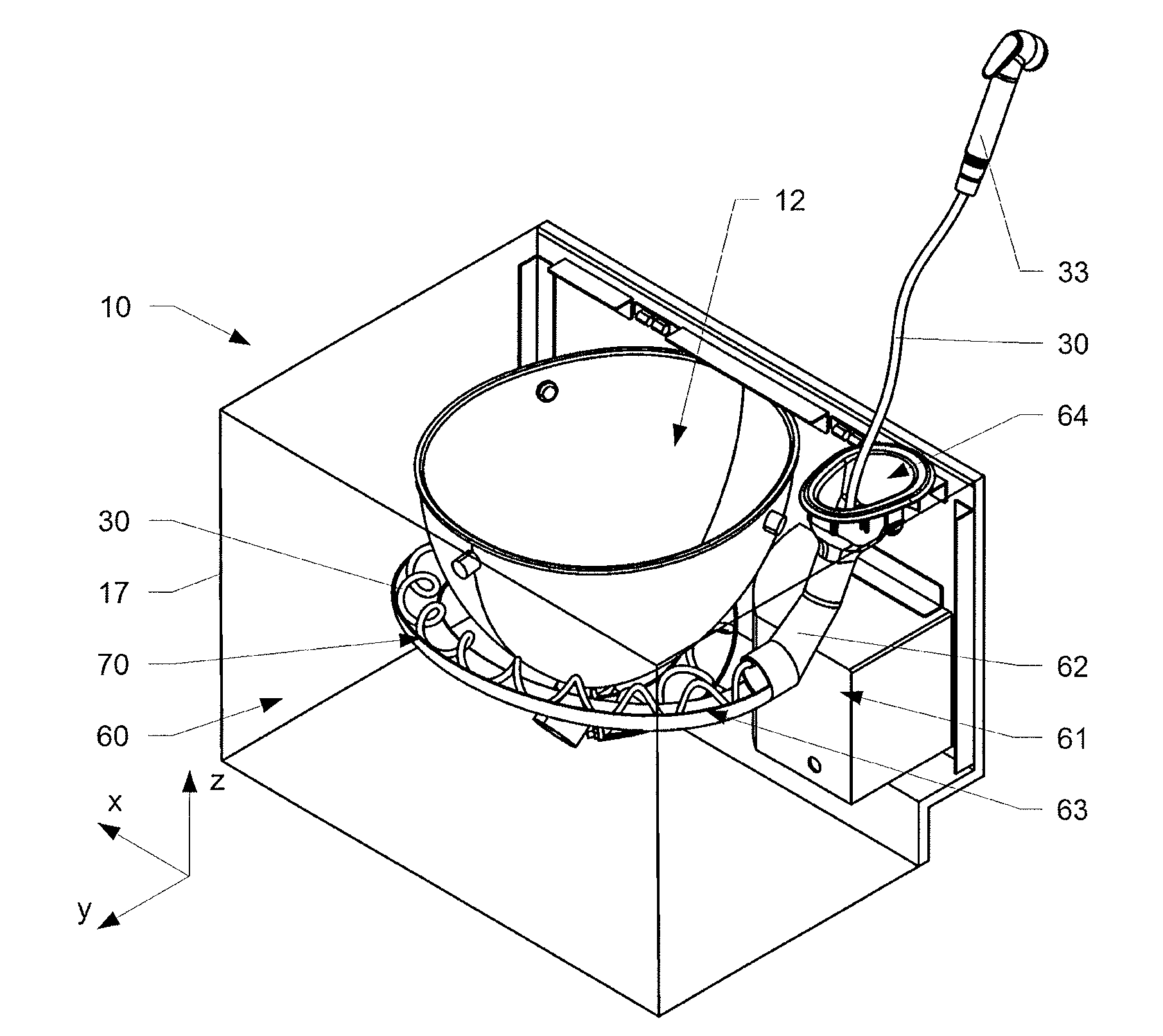
[0039] FIG. 1 to FIG. 4 schematically show a first embodiment of a sanitary module 10 with a storage device 60 according to the invention. As mentioned, the invention is not limited to being used for sanitary applications only. As shown in FIG. 1, the sanitary module 10 shown comprises a bowl 12 of a flush toilet, a hand-held handpiece 33 that serves as a bidet spray, respectively source of water, and an auxiliary stowage 13 in order to e.g. stow bathroom tissues or other goods. As indicated in FIG. 2, the sanitary module 10 comprises an installation space 11 which in a vehicle will be typically restricted in outer spatial dimensions by encompassing structural parts 17.
[0040] In the shown embodiment, beside the bowl 12 and the auxiliary stowage 13 which both reach (as modules) into and thereby take influence on the installation space 11, the installation space 11 in addition can be delimited by different configurations of multiple modules 14 that typically fill a significant portion of the installation space 11, as e.g. shown in FIG. 2 and FIG. 3.
[0041] In the embodiment as shown in FIG. 2 and FIG. 3 a storage device 60 is arranged adjacent to a front wall 16 of the sanitary module 10, mechanically interconnected to the sanitary module 10 by fastening means 67. One advantage of the invention is that at least the first housing member 61 can be flexibly adopted to the available installation space 11 and the therein arranged other modules, while the other parts of the storage device can remain standardized.
[0042] As shown e.g. in FIG. 3 and FIG. 4, the hose storage device 60 comprises a first housing member 62 that encloses a first storage compartment 63 which is configured to receive a portion of the hose 30 via hose port 64 arranged in the first housing member 62. The first storage compartment 63 is formed such that the portion of the hose 30 when being arranged in the first storage compartment 63 takes a shape that is at least partially defined by the shape of the first storage compartment 63, as illustrated e.g. in FIG. 4.
[0043] The first housing member 62 is shaped such that it fits in the free installation volume of the installation space 11 while ensuring that a portion of a hose 30 arranged in the first compartment 63 is not bent below a structurally critical minimum bending radius r of it. Therefore the storage device 60 for the extractable hose 30 is arranged in the installation space 11. The storage device 60 comprises the first housing member 62 defining on the inside a first storage compartment 63. As mentioned above the first storage compartment 63 is configured to house at least a portion of the hose 30 which extends from the first storage compartment 63 via the hose port 64 arranged at one end of the first housing member 62. The first housing member 62 has at least one spatial curved wall section 69 adopted to the contour of at least one module 14 extending into the installation space 11.
[0044] FIG. 5 shows the storage device 60 as shown in FIGS. 1-4 in a front view. FIG. 6 is showing the storage device 60 in a separated manner. FIGS. 7-8 are showing the inside of the storage device 60. The storage device 60 comprises a housing 61 with a first housing member 62 encompassing a first storage compartment 63 and a second housing member 65 encompassing a second storage compartment 66 for storing a hose 30 on the inside. The hose 30 can be extracted from and inserted into the storage device 60 via a hose port 64 against a force of a retraction mechanism 70 arranged in the second housing member 65 and as e.g. visible in FIGS. 7-8.
[0045] In the shown variation, the retraction mechanism 70 comprises a rotatable mounted deflection roller 70 which is arranged linear displaceable in a transversal direction (arrow 76) against the force of a spring member 72. The spring member 72, e.g. in the form of a coil spring or a rubber band having a certain length, extends along an upper edge 73 of the second housing member 65 parallel to the hose 30. The spring member 72 is deflected by at least one guide roller 75. One advantage of the shown retraction mechanism 70 is that it is comparatively flat and compact, and therefore easy to install in narrow spaces.
[0046] Depending on the installation space, as shown hereinafter, other kinds of retraction mechanisms can be foreseen if appropriate. A rear end of the flexible hose 30 is interconnected to an inlet 74. The hose 30 is deflected by the deflection roller 71 and then continues into the first storage compartment of the first housing member 62. While the second housing member 65 comprising the retraction mechanism 70 preferably are standardized parts, the first housing member 62 is an individually adopted element which is designed according installation space available. Good results are achieved if the first housing member 62 is at least partially made by an additive manufacturing process, such as e.g. 3D-printing. The first housing member 62 comprises a protuberance 59 forming the lowest point of the housing 61. In the shown variation as visible in FIG. 7 the protuberance 59 is designed to receive a part of the hose 30 when the shower hear 33 is arranged in the hose port 64. Furthermore the protuberance 59 is suitable to collect leaked liquid which e.g. flows back along the hose. It can be interconnected to a drainage 81. Alternatively or in addition a liquid sensor (humidity sensor) can be foreseen to indicate presence of liquid in the protuberance 59.
[0047] As e.g. visible in FIGS. 5-6 the first and the second housing member 62, 65 are designed as separate parts which are interconnected to each other by a first and a second flange 77, 78.
[0048] A storage device 60 for an extractable hose 30 is arranged in an installation space 11. The storage device 60 comprises a first housing member 62 comprising on the inside a first storage compartment 63, which is configured to house at least a portion of the hose 30 which is extractable from the first storage compartment via a hose port 64 arranged at the first housing member 62. The first housing member 62 has at least one spatial curved wall section 69 specifically adopted to an contour of at least one module 14 extending into the installation space 11 which normally prevents the installation of standardized parts. In case of several relatively similar arrangements, the available installation space 11 can defined by an overlay of at least two configurations of modules 14 extending into the installation space 11. The first storage compartment 63 in the first housing member 62 may have a variable cross-section along the length of the hose 30. Alternatively or in addition, the first storage compartment 63 in the first housing member 62 may have a protuberance 59 suitable to receive part of the hose 30. As e.g. visible in FIGS. 5-6 the protuberance preferably forms the lowest point of the first housing member 62 such that e.g. leaking fluid can be collected therein. If appropriate the first housing member 62 may comprise a fluid outlet 81 and/or a liquid sensor 82. In a preferred variation, the first housing member 62 is at least partially made by an additive manufacturing process, e.g. 3D printing and/or lamination of a composite material. Alternatively or in addition, the first housing member 62, at least during installation in the installation, space 11 can have an adjustable design. However, it is preferable that the first housing member 62 does not deform in a negative manner, when the hose 30 is extracted from it. The first housing member 62 may in the longitudinal direction of the hose 30 comprise several segments which during installation are adjustable relative to each other, e.g. the adjustable segments are pivot connected to each other. The first storage compartment 63 is formed such that a portion of the hose 30 when being inserted in the first storage compartment 63 is brought to a predefined shape by means of gravity. To reduce friction, especially in narrow and bend areas, the first housing member 62 can at least partially be coated by a friction reducing means, such as pads made from or coated with e.g. Teflon.RTM. or a similar material.
[0049] In the variations as shown in FIGS. 1-8 the storage device 60 comprises a second housing member 65 comprising a second storage compartment 66 and being interconnected with the first housing member 62 such that the first and the second storage compartment 63, 66 form a continuous compartment for receiving at least a portion of the hose 30. The first and the second housing member 62, 65 are interconnected with each other in a separable manner by a first and a second flange 77, 78. The storage device 60 comprises a retraction mechanism 70 for the hose 30, which is arranged in the second housing member 65. The first housing member 62 at least partially transfers the force necessary to extract the hose 30 from the hose port 64 between the hose port 64 and the retraction mechanism 70 interconnected to the second housing member 65. The first and/or the second housing member 62, 65 may comprise at least one connecting point 68 to connect an auxiliary device, such as a mixture valve 50 to the storage device 60. The storage device 60 may comprise multiple connecting points 68 arranged in a regular pattern. Good results can be achieved when the first housing member 62 and/or the second housing member 65 are at least partially made from a plastic material, in particular from a polyetherimide PEI and/or a polyamide PA or from a ceramic material or from a metal.
[0050] FIGS. 10-12 and FIGS. 13-14 show a second and a third variation of a sanitary module 10 in a simplified manner. Both modules comprise an installation space 11 into which modules 14 are arranged or reach into, e.g. such as a bowl 12. In the variation according to FIGS. 10-12 the first housing member 62 has a tubular shape encompassing a first storage compartment 63 having an in principal constant diameter along the general extension of the hose 30. The wall of the first housing member 62 is spatially curved around the bowl 12 which extends into the installation space 11. In this variation the hose 30 is itself comprises a helical spring section and is thereby elastically expandable from the hose port 64. The hose 30 incorporates thereby the retraction mechanism 70. The outer diameter of the helical shaped hose 30 is smaller than the inside diameter of the tubular first housing member 62. FIG. 11 shows the hose in the contracted position completely arranged inside the first storage compartment. FIG. 12 shows the hose 30 partially extended through the hose port 64. One advantage of the shown variation is the simple, robust and compact design. The design of the first housing member 62 can easily be adopted to the specific installation space 11 available in the sanitary module 10. If appropriate, the first housing member can be equipped by a drainage which is preferably arranged at the lowest position of the first housing member. FIGS. 13-14 show a third variation of a storage device 60. The storage device 60 comprises an extractable hose 30 and is arranged in a narrow installation space 11. The storage device 60 comprises a first housing member 62 defining a first storage compartment 63. The first storage compartment 63 is configured to house at least a portion of the hose 30 which is extractable from the first storage compartment 63 via a hose port 64 arranged at one end of the first housing member 62. The outer wall of the first housing member 62 is spatial curved eluding the contour of the bowl 12 which extending into the installation space 11. The first housing member 62 can at least during installation in the installation space 11 have an adjustable design, e.g. by being bendable. The first housing member 62 can in longitudinal direction of the hose 30 comprise several segments (not shown in detail) which during installation are adjustable relative to each avoiding obstacles. Good results can be achieved when the adjustable segments may be pivot connected to each other. The storage device 60 comprises a second housing member 65 which is interconnected to the first housing. It a second storage compartment 66. The first and the second storage compartment 63, 66 form a continuous compartment for receiving at least a portion of the hose 30.
* * * * *
D00000
D00001
D00002
D00003
D00004
D00005
D00006
D00007
XML
uspto.report is an independent third-party trademark research tool that is not affiliated, endorsed, or sponsored by the United States Patent and Trademark Office (USPTO) or any other governmental organization. The information provided by uspto.report is based on publicly available data at the time of writing and is intended for informational purposes only.
While we strive to provide accurate and up-to-date information, we do not guarantee the accuracy, completeness, reliability, or suitability of the information displayed on this site. The use of this site is at your own risk. Any reliance you place on such information is therefore strictly at your own risk.
All official trademark data, including owner information, should be verified by visiting the official USPTO website at www.uspto.gov. This site is not intended to replace professional legal advice and should not be used as a substitute for consulting with a legal professional who is knowledgeable about trademark law.