Oxygen Evolution Electrocatalysts With Carbon Coated Cobalt (ii, Iii) Oxide Layers
Li; Lain-Jong ; et al.
U.S. patent application number 16/078673 was filed with the patent office on 2019-02-21 for oxygen evolution electrocatalysts with carbon coated cobalt (ii, iii) oxide layers. This patent application is currently assigned to SABIC Global Technologies B.V.. The applicant listed for this patent is SABIC Global Technologies B.V.. Invention is credited to Hicham Idriss, Lain-Jong Li, Xiulin Yang.
| Application Number | 20190055657 16/078673 |
| Document ID | / |
| Family ID | 58670103 |
| Filed Date | 2019-02-21 |


View All Diagrams
| United States Patent Application | 20190055657 |
| Kind Code | A1 |
| Li; Lain-Jong ; et al. | February 21, 2019 |
OXYGEN EVOLUTION ELECTROCATALYSTS WITH CARBON COATED COBALT (II, III) OXIDE LAYERS
Abstract
Oxygen evolution reaction (OER) catalysts and uses thereof are described. An OER catalyst can include a carbon support, a discontinuous catalytic cobalt (II,III) oxide (Co.sub.3O.sub.4) nanolayer in direct contact with the carbon support, and an amorphous continuous carbon layer. The Co.sub.3O.sub.4 nanolayer is positioned between the carbon support and an amorphous continuous carbon layer.
| Inventors: | Li; Lain-Jong; (Thuwal, SA) ; Yang; Xiulin; (Thuwal, SA) ; Idriss; Hicham; (Thuwal, SA) | ||||||||||
| Applicant: |
|
||||||||||
|---|---|---|---|---|---|---|---|---|---|---|---|
| Assignee: | SABIC Global Technologies
B.V. Bergen op Zoom NL |
||||||||||
| Family ID: | 58670103 | ||||||||||
| Appl. No.: | 16/078673 | ||||||||||
| Filed: | April 13, 2017 | ||||||||||
| PCT Filed: | April 13, 2017 | ||||||||||
| PCT NO: | PCT/IB2017/052154 | ||||||||||
| 371 Date: | August 22, 2018 |
Related U.S. Patent Documents
| Application Number | Filing Date | Patent Number | ||
|---|---|---|---|---|
| 62324093 | Apr 18, 2016 | |||
| Current U.S. Class: | 1/1 |
| Current CPC Class: | Y02E 60/366 20130101; B01J 23/75 20130101; C25B 11/0478 20130101; C25B 1/04 20130101; B01J 35/0033 20130101; C25B 11/0415 20130101; B01J 33/00 20130101; Y02E 60/36 20130101; B01J 35/002 20130101 |
| International Class: | C25B 11/04 20060101 C25B011/04; C25B 1/04 20060101 C25B001/04 |
Claims
1. An oxygen evolution reaction (OER) electrocatalyst comprising: a carbon support; a discontinuous catalytic cobalt nanolayer comprising a compound selected from the group consisting of CoP, CoP.sub.2 and Co.sub.3O.sub.4 that is in direct contact with the carbon support; and an amorphous continuous carbon layer, wherein the discontinuous catalytic cobalt nanolayer is positioned between the carbon support and the amorphous continuous carbon layer.
2. The OER electrocatalyst of claim 1, wherein the thickness of the amorphous carbon layer is 0.5 to 15 nm.
3. The OER electrocatalyst of claim 1, wherein the discontinuous catalytic cobalt nanolayer has a thickness of 1 to 1000 nm.
4. The OER electrocatalyst of claim 1, wherein the carbon support is carbon fiber paper.
5. The OER electrocatalyst of claim 1, wherein the discontinuous catalytic nanolayer comprises a Co.sub.3O.sub.4 compound and the discontinuous layer further comprises Co oxide (CoO), cobalt hydroxide (Co(OH).sub.2), or both.
6. The OER electrocatalyst of claim 1, wherein the discontinuous catalytic nanolayer comprises the CoP, CoP.sub.2 or both.
7. The OER electrocatalyst of claim 4, wherein the carbon support has been acid treated.
8. The OER electrocatalyst of claim 1, wherein the discontinuous catalytic cobalt nanolayer comprises Co.sub.3O.sub.4.
9. An electrode comprising the OER electrocatalyst of claim 1.
10. An apparatus comprising the electrode of claim 9, wherein the apparatus is for the electrolytic splitting of water into hydrogen and oxygen, the apparatus further comprising a container for holding an aqueous electrolyte, a counter electrode, and a power source configured to apply a voltage across the electrodes.
11. A method of producing the electrocatalyst of claim 1 having a nanolayer comprising Co.sub.3O.sub.4 compound, the method comprising: (a) obtaining a carbon support comprising a discontinuous cobalt precursor nanolayer deposited on the carbon support; (b) thermally treating the carbon support from step (a) under vacuum to convert the cobalt species to CoO; and (c) thermally treating the carbon support from step (b) in an oxygen-rich environment to convert the CoO Co.sub.3O.sub.4.
12. The method of claim 11, wherein the carbon support from step (a) comprises a carbon-containing layer deposited on the discontinuous cobalt precursor layer, and wherein the thermal treating steps (b) and/or (c) convert the carbon-containing layer into an amorphous carbon layer, wherein the amorphous carbon layer is continuous.
13. The method of claim 11, wherein the carbon support material comprises carbon paper.
14. The method of claim 11, wherein obtaining the carbon support material of step (a) comprises: (i) acid treating the carbon support; and (ii) contacting the acid treated carbon support with the cobalt precursor under conditions sufficient to deposit the discontinuous cobalt precursor nanolayer on the surface of the carbon support.
15. The method of claim 14, wherein the deposition in step (ii) is electrochemical deposition (ECD), atomic layer deposition (ALD) or chemical vapor deposition (CVD).
16. The method of claim 12, wherein the carbon-containing layer comprises a hydrocarbon, a sugar-based compound, a sulfonated carbon compound, nitrogen-based carbon compound, carbon-based monomer, aromatic compound, or any combination thereof, preferably glucose.
17. The method of claim 11, wherein the amorphous carbon layer has a thickness of 0.5 nm to 15 nm.
18. A method of producing the OER electrocatalyst of claim 1 having a nanolayer comprising the CoP compound the CoP.sub.2 compound or both, the method comprising: contacting a carbon support material having a cobalt precursor deposited thereon; and thermally treating the cobalt precursor and reacting with a phosphorous source in an oxygen deficient atmosphere to produce the CoP and/or CoP.sub.2 nanolayer on the carbon support.
19. A method for the electrolytic splitting of water into hydrogen and/or oxygen, the method comprising: electrolyzing an aqueous solution comprising electrolyte and the OER catalysts of claim 1; and producing hydrogen gas and oxygen gas.
20. The OER electrocatalyst of claim 19, wherein the aqueous solution is an acidic solution or a basic solution.
Description
CROSS REFERENCE TO RELATED APPLICATIONS
[0001] This application claims the benefit of priority of U.S. Provisional Patent Application No. 62/324,093 filed Apr. 18, 2016, which is hereby incorporated by reference in its entirety.
BACKGROUND OF THE INVENTION
A. Field of the Invention
[0002] The invention generally concerns oxygen evolution reaction (OER) electrocatalysts that includes a discontinuous catalytic Co.sub.3O.sub.4 nanolayer in direct contact with a carbon support and an amorphous continuous carbon layer. The discontinuous Co.sub.3O.sub.4 catalytic nanolayer is between the carbon support and the amorphous continuous carbon layer.
B. Description of Related Art
[0003] Use of hydrogen as an energy source has increased with the needed minimize CO.sub.2 emission from fossil fuels. One source of hydrogen can be from the splitting of water into hydrogen and oxygen. Water splitting can be achieved on a large scale using an electrochemical apparatus (e.g., electrolyzer). In an electrolyzer, water is split into hydrogen (H.sub.2) and oxygen (O.sub.2) by passing electricity through a water solution that includes an electrolyte to split the water. The hydrogen production in an electrolytic water splitting reaction can be limited by the kinetics of oxygen evolution reaction (OER) at the anodes. Various solutions have been attempted to improve the production of oxygen at the anode. For example, electrocatalysts containing metal or oxide forms of precious metals such as iridium (Ir), ruthenium (Ru), and their alloys have been coated on the anode. However, their scarce nature and associated high-cost considerably limit large-scale implementation of industrial devices. Furthermore, these catalysts can be unstable in corrosive acids. Other attempts to improve the efficiency of the oxygen production include the use of cobalt (Co), iron (Fe), nickel (Ni) and manganese (Mn) oxides/hydroxides, phosphides, dichalcogenides and some non-metallic compounds, as OER catalysts in an alkaline solution. However, the development of alkaline water electrolysis has been restricted by several issues including low current density and cross-diffusion of the produced gases. By contrast, the proton exchange membrane (PEM) electrolysis in acids has shown critical advantages in current densities, voltage efficiency and purity of produced gases. Various anode catalysts suitable in acids, such as ruthenium oxide (RuO.sub.2) and iridium oxide (IrO.sub.2), and their ternary oxides have been developed for use in these types of applications. To reduce the usage of precious metals (e.g., Ru and Ir), other metal elements including tin (Sn), antimony (Sb), niobium (Nb), lead (Pb), nickel (Ni), copper (Cu), tantalum (Ta), zirconium (Zr), and molybdenum (Mo) have been added to precious metals to the form alloys or core-shell structures. However, anodes made with these metals also suffered from corrosion during use.
[0004] Recent attempts to make OER electrocatalysts have centered on the use of cobalt (II, III) oxides (Co.sub.3O.sub.4). Co.sub.3O.sub.4 has shown catalytic properties and chemical stability in alkaline solutions, however, the application of Co.sub.3O.sub.4 for OER in acidic medium has not been successful as the Co.sub.3O.sub.4 suffers from corrosion at potentials higher than 1.47 V (vs. RHE). At these potentials, cobalt (IV) oxide (CoO.sub.2) can be formed from the Co.sub.3O.sub.4, which can then decompose into soluble cobalt (II) oxide CoO with the simultaneous liberation of the O.sub.2. Furthermore, the cobalt OER electrodes suffer from poor adhesion of the Co.sub.3O.sub.4 to the electrode substrate (e.g., titanium foil substrates). Various attempts to improve electrodes containing cobalt have been disclosed. By way of example, Leng et al. in "Carbon-encapsulated Co.sub.3O.sub.4 Nanoparticles as Anode Materials with Super Lithium Storage Performance", Scientific Reports, November 2015, pp. 1-11 discloses the use of carbon-encapsulated Co.sub.3O.sub.4 nanoparticles (i.e., Co.sub.3O.sub.4@C structures) embedded in a carbon support. These electrodes suffer in that the charge flow to and from the cobalt core is inefficient due to the cobalt being isolated from the solution by two layers of carbon. Various attempts to make cobalt OER catalysts include cobalt-carbon composites (See, Chinese Patent No. 104056630 to Yiming et al.) and uniformly distributed metal hydroxides in holes of porous carbon skeletons (See, Chinese Patent Application Publication No. 10495582 to Cheng et al.). These OER catalysts suffer from anodic corrosion at potentials higher than 1.47 V.
[0005] As discussed above, many of the OER catalysts currently available suffer from anodic corrosion in acidic environments, leaching of catalytic material from the support material, and/or manufacture of the OER catalyst is not cost effective.
SUMMARY OF THE INVENTION
[0006] A discovery has been made that provides an elegant solution to the problems associated with the use of cobalt species in OER catalysts. The solution is premised on the idea of providing a discontinuous catalytic cobalt (II, III) oxide (Co.sub.3O.sub.4) nanolayer between a carbon support and an amorphous continuous carbon layer. The discontinuous catalytic Co.sub.3O.sub.4 nanolayer is in direct contact with the carbon support. Without wishing to be bound by theory it is believed that the when OER catalyst is used as in a set of electrodes in an electrolysis reaction, direct contact of the cobalt with the carbon support provides for efficient charge transfer between the cobalt species and the carbon support, while the carbon layer inhibits exfoliation of the catalytic Co.sub.3O.sub.4 from the surface of the carbon support. Notably, the solution of the present invention does not require use of precious metals to provide low over-potentials and acceptable current density in acid or alkaline solutions. Furthermore, the OER electrocatalyst is stable (e.g., doe not breakdown) over an extended period of time in both acid and alkaline solutions.
[0007] The solution also includes a novel method to produce an OER electrocatalyst. The method includes a 2-step calcination process of a carbon support that includes a discontinuous cobalt precursor layer deposited on the carbon support. This first step can include heat treating the carbon support under vacuum conditions (oxygen lean conditions). In this first step, the surface integrity of the carbon support (e.g., carbon paper or carbon cloth) is reinforced, and the cobalt precursor is converted CoO. The second calcination step heat treats the carbon support from the first step in an oxygen rich environment to convert the CoO to Co.sub.3O.sub.4 without degrading the mechanical strength of the Co.sub.3O.sub.4-carbon support interface. The discontinuous Co.sub.3O.sub.4 layer can be coated with an amorphous carbon layer. Such a carbon layer can adhere the Co.sub.3O.sub.4 to the carbon support.
[0008] In a specific aspect of the invention, an oxygen evolution reaction (OER) electrocatalyst is described. The OER electrocatalyst can include a carbon support; a discontinuous catalytic Co.sub.3O.sub.4 nanolayer in direct contact with the carbon support; and an amorphous continuous carbon layer (e.g., carbon fiber paper and/or acid treated carbon fiber paper). The discontinuous catalytic Co.sub.3O.sub.4 nanolayer can be positioned between the carbon support and the amorphous continuous carbon layer. The thickness of the amorphous carbon layer can be 0.5 to 15 nm, preferably 1 nm to 10 nm, more preferably 3 nm to 5 nm and/or the discontinuous catalytic Co.sub.3O.sub.4 nanolayer has a thickness of 1 to 1000 nm, preferably 500 nm. In an instance, the carbon support can be substantially coated with the discontinuous catalytic Co.sub.3O.sub.4 nanolayer. In some instances, the discontinuous catalytic Co.sub.3O.sub.4 nanolayer can also include Co(II) oxide (CoO), cobalt hydroxide (Co(OH).sub.2), or both. By way of example, the OER catalyst can include up to 25 wt. % of Co(OH).sub.2 and 75 wt. % or more of Co.sub.3O.sub.4. In certain instances, the OER electrocatalyst can have a ratio of the Disorder (D)-Raman peak to the Graphite (G)-Raman peak (I.sub.D/I.sub.G) from 0.2 up to 0.9, preferably 0.6, which can indicate minimal defects on the surface of the carbon support. The OER electrocatalyst of the present invention can be included in an electrode. Such an electrode can be included in an apparatus (e.g., an electrolyzer) for the electrolytic splitting of water into hydrogen and/or oxygen. The apparatus can also include a container for holding an aqueous electrolyte, a counter electrode, and a power source configured to apply a voltage across the electrodes.
[0009] In yet another aspect of the invention, a method of producing an OER electrocatalyst is described. The method can include: (a) obtaining a carbon support comprising a discontinuous cobalt precursor nanolayer deposited on the carbon support; (b) thermally treating the carbon support from step (a) under vacuum to convert the cobalt species to CoO; and (c) thermally treating the carbon support from step (b) in an oxygen-rich environment to convert the CoO to cobalt (KIM oxide (Co.sub.3O.sub.4). In some instances, the carbon support from step (a) can include a carbon-containing (e.g., a hydrocarbon, a sugar-based compound, a sulfonated carbon compound, nitrogen-based carbon compound, carbon-based monomer, aromatic compound, or any combination thereof, preferably glucose) layer deposited on the discontinuous cobalt precursor layer, and the thermal treating steps (b) and/or (c) convert the carbon-containing layer into an amorphous carbon layer. Carbon support material (e.g., carbon fiber paper or carbon cloth) of step (a) can be obtained by (i) acid treating the carbon support; and (ii) contacting the acid treated carbon support with the cobalt species precursor under conditions sufficient to deposit the discontinuous cobalt species precursor nanolayer on the surface of the carbon support. By way of example, the cobalt precursor can be deposited using electrochemical deposition (ECD), atomic layer deposition (ALD) or chemical vapor deposition (CVD).
[0010] In some instances of the present invention, a method for the electrolytic splitting of water into hydrogen and/or oxygen is described. The method can include electrolyzing an aqueous solution comprising electrolyte and any one of the OER or HER catalysts of the present invention and producing hydrogen gas, oxygen gas, or both. The hydrogen gas, the oxygen gas, or both can be collected.
[0011] The following includes definitions of various terms and phrases used throughout this specification.
[0012] The phrase "water splitting" or any variation of this phrase describes the chemical reaction in which water is separated into oxygen and hydrogen.
[0013] The terms "about" or "approximately" are defined as being close to as understood by one of ordinary skill in the art. In one non-limiting embodiment, the terms are defined to be within 10%, preferably within 5%, more preferably within 1%, and most preferably within 0.5%.
[0014] The terms "wt. %", "vol. %", or "mol. %" refers to a weight, volume, or molar percentage of a component, respectively, based on the total weight, the total volume of material, or total moles, that includes the component. In a non-limiting example, 10 grams of component in 100 grams of the material is 10 wt. % of component.
[0015] The term "substantially" and its variations are defined to include ranges within 10%, within 5%, within 1%, or within 0.5%.
[0016] The terms "inhibiting" or "reducing" or "preventing" or "avoiding" or any variation of these terms, when used in the claims and/or the specification includes any measurable decrease or complete inhibition to achieve a desired result.
[0017] The term "effective," as that term is used in the specification and/or claims, means adequate to accomplish a desired, expected, or intended result.
[0018] The use of the words "a" or "an" when used in conjunction with any of the terms "comprising," "including," "containing," or "having" in the claims, or the specification, may mean "one," but it is also consistent with the meaning of "one or more," "at least one," and "one or more than one."
[0019] The words "comprising" (and any form of comprising, such as "comprise" and "comprises"), "having" (and any form of having, such as "have" and "has"), "including" (and any form of including, such as "includes" and "include") or "containing" (and any form of containing, such as "contains" and "contain") are inclusive or open-ended and do not exclude additional, unrecited elements or method steps.
[0020] The electrocatalysts of the present invention can "comprise," "consist essentially of," or "consist of" particular ingredients, components, compositions, etc. disclosed throughout the specification. With respect to the transitional phase "consisting essentially of," in one non-limiting aspect, a basic and novel characteristic of the OER and/or HER electrocatalysts of the present invention are their abilities to catalyze a water-splitting reaction.
[0021] Other objects, features and advantages of the present invention will become apparent from the following figures, detailed description, and examples. It should be understood, however, that the figures, detailed description, and examples, while indicating specific embodiments of the invention, are given by way of illustration only and are not meant to be limiting. Additionally, it is contemplated that changes and modifications within the spirit and scope of the invention will become apparent to those skilled in the art from this detailed description. In further embodiments, features from specific embodiments may be combined with features from other embodiments. For example, features from one embodiment may be combined with features from any of the other embodiments. In further embodiments, additional features may be added to the specific embodiments described herein.
BRIEF DESCRIPTION OF THE DRAWINGS
[0022] Advantages of the present invention may become apparent to those skilled in the art with the benefit of the following detailed description and upon reference to the accompanying drawings.
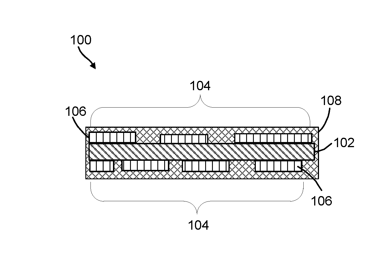
[0023] FIGS. 1A-1C are cross-sectional illustrations of the catalyst of the present invention. FIG. 1A depicts the discontinuous Co.sub.3O.sub.4 nanolayer on two sides of a carbon support. FIG. 1B depicts the discontinuous Co.sub.3O.sub.4 nanolayer on one side of a carbon support. FIG. 1C is a top view of the catalyst depicting discontinuous Co.sub.3O.sub.4 nanolayer on the carbon support.
[0024] FIG. 2 is a schematic of a method to make an OER electrocatalyst using a 2-step thermal treating method of the present invention.
[0025] FIG. 3 is a schematic of a method to make an OER electrocatalyst having a carbon-layer using a 2-step thermal treating method of the present invention.
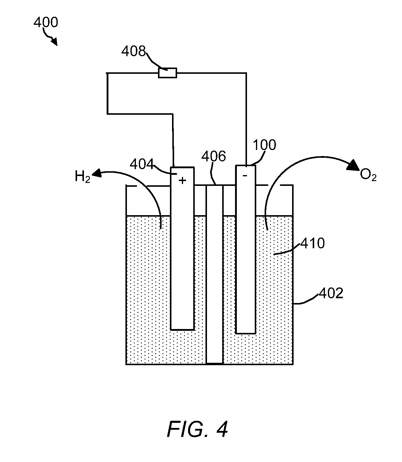
[0026] FIG. 4 is a schematic of a water-splitting reaction using the OER catalyst of the present invention.
[0027] FIG. 5 shows X-ray Diffraction (XRD) patterns of catalysts of the present invention and comparative catalysts.
[0028] FIG. 6 shows X-ray Diffraction (XRD) patterns of catalysts of the present invention and comparative catalysts before and after acid-OER testing.
[0029] FIG. 7A is a scanning electron microscopy (SEM) image of electrodeposited Co-species on CP.
[0030] FIG. 7B is an SEM image of and the catalyst of the present invention.
[0031] FIG. 8A is a transmission electron microcopy (TEM) image of a flake peeled off from an electrode that includes the catalyst of the present invention
[0032] FIG. 8B is a high-resolution TEM image of the image of a flake peeled off from an electrode that includes the catalyst of the present invention The inset in FIG. 8B is the diffraction pattern.
[0033] FIG. 8C is high-angle annular diffraction field scanning transmission electron microscopy (HAADF-STEM) image of the catalyst of the present invention.
[0034] FIG. 9 shows Raman spectra of catalysts of the present invention and comparative catalysts.
[0035] FIG. 10 shows Raman spectra of carbon paper under various heat treatments.
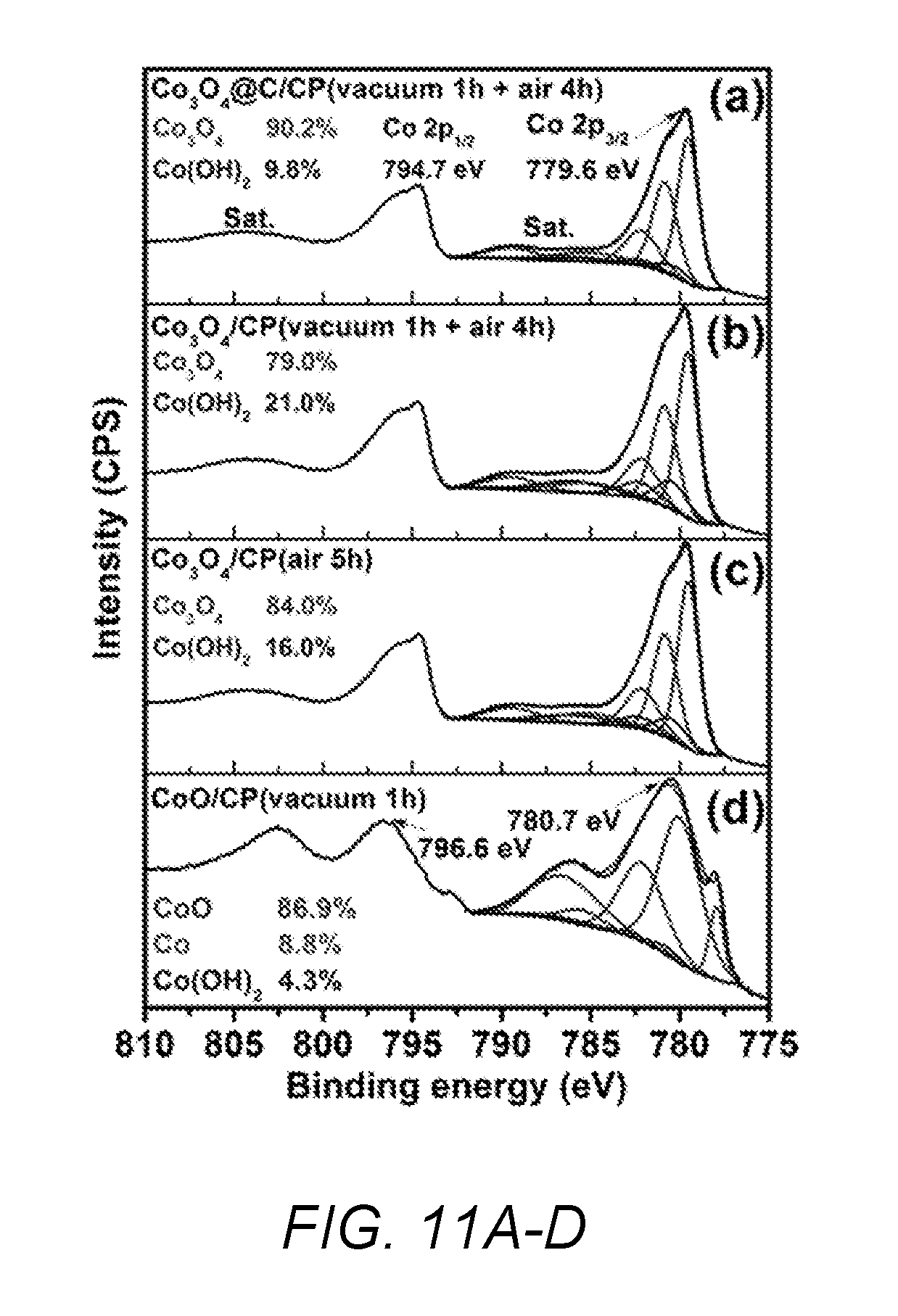
[0036] FIGS. 11A-D shows X-ray photoelectron spectroscopy (XPS) spectra of Co 2p for (A) catalyst of the present invention, (B) catalyst of the present invention without a carbon layer, (C) comparative Co.sub.3O.sub.4/CP catalyst and (D) comparative CoO/CP catalyst.
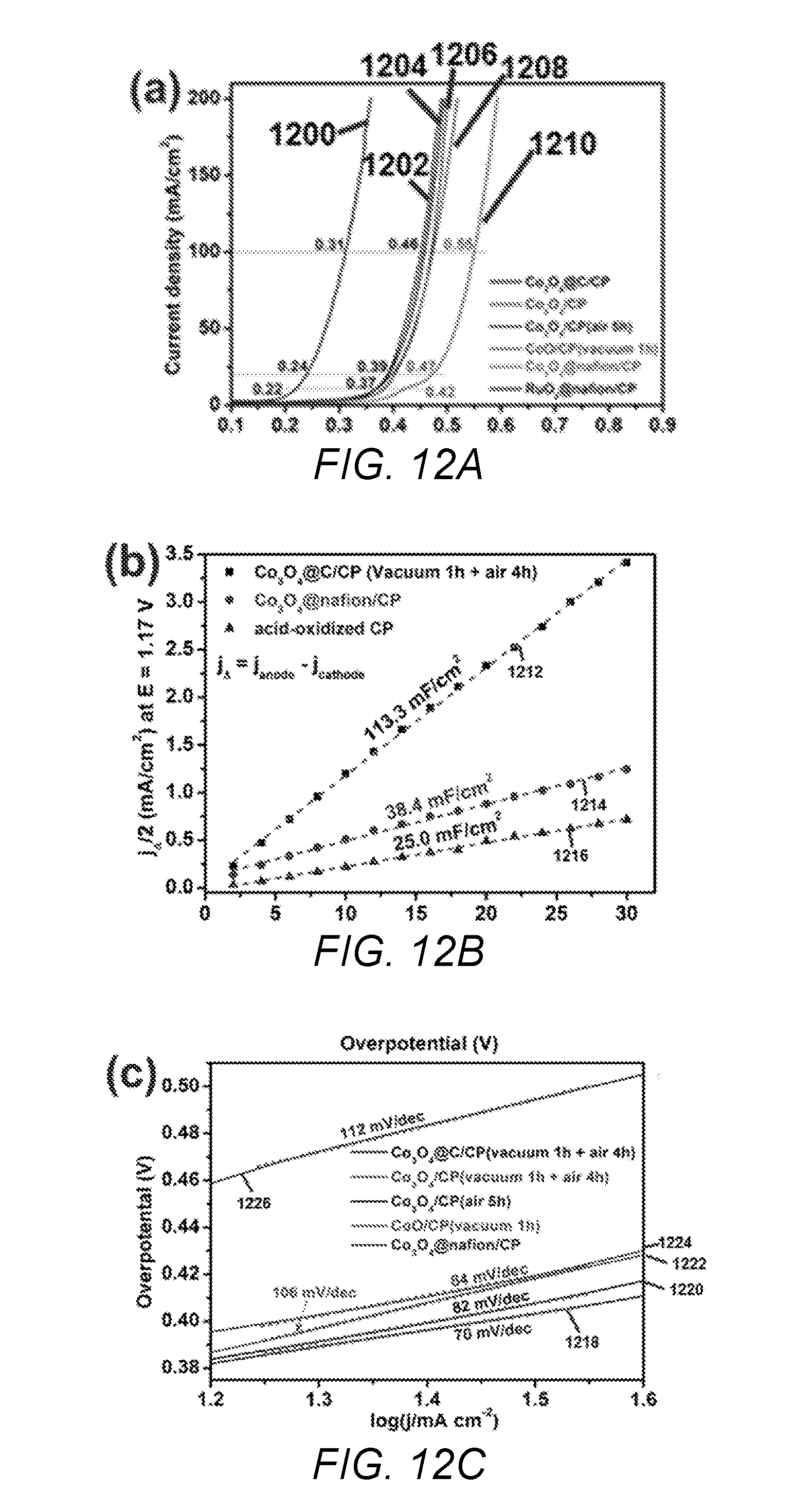
[0037] FIGS. 12A-12C depict graphs of electrochemical measurements of catalysts of the present invention and comparative catalysts. FIG. 12A are polarization curves of the catalysts of the present invention and comparative catalysts measured in 0.5 M H.sub.2SO.sub.4 with a scan rate of 5 mV/s, where the current is normalized by the geometrical area of carbon fiber paper and the potential is after internal resistance correction; FIG. 12B are graphs of double-layer capacitance (C.sub.dl) for the catalysts of the present invention and comparative catalysts; FIG. 12(C) are Tafel slopes extracted from the polarization curves in FIG. 12A.
[0038] FIG. 13 shows SEM images of Co(OH).sub.2 precursor material, cobalt oxide, and cobalt phosphide catalysts of the present invention prepared at various temperatures.
[0039] FIG. 14 shows the electro-catalytic activity of a comparative catalyst and the cobalt phosphide catalysts of the present invention for OER in water.
[0040] FIG. 15 shows electro-catalytic activity of a comparative catalyst and the cobalt phosphide catalysts of the present invention for HER in water.
[0041] While the invention is susceptible to various modifications and alternative forms, specific embodiments thereof are shown by way of example in the drawings and may herein be described in detail. The drawings may not be to scale.
DETAILED DESCRIPTION OF THE INVENTION
[0042] The solution to the problems associated with the conventional OER catalysts has been discovered. The solution lies in an OER catalyst that has a discontinuous catalytic Co.sub.3O.sub.4 nanolayer between a carbon support and an amorphous carbon layer, where the discontinuous catalytic Co.sub.3O.sub.4 nanolayer is in direct contact with the carbon support. Furthermore, the methods of the present invention to make the OER catalyst provide means to attach the Co.sub.3O.sub.4 to the carbon support without degrading the mechanical strength of the Co.sub.3O.sub.4-carbon support interface. In situ formation of a layer of amorphous carbon on top of Co.sub.3O.sub.4 can attach the catalytic Co.sub.3O.sub.4 discontinuous nanolayer to the carbon support which inhibits detachment or dissolution of the cobalt species from the carbon support, thereby providing a catalyst that is stable in acidic or basic medium. Notably, the Co.sub.3O.sub.4 OER catalyst as shown in the Examples section is highly active and has a longer lifetime than conventional catalysts (e.g., OER catalyst made from RuO.sub.2 nanoparticles on the same carbon support covered by an ionic polymer, and/or an OER catalyst made from Co.sub.3O.sub.4 nanoparticles casted on carbon paper covered by an ionic polymer (e.g., Nafion.RTM., DuPont, USA)). The coated carbon layers effectively inhibit the direct degradation of CP surface as well as provided a mechanical supporting layer to further inhibit the exfoliation of the catalytic discontinuous Co.sub.3O.sub.4 nanolayer from the substrate.
[0043] These and other non-limiting aspects of the present invention are discussed in further detail in the following sections.
A. OER Electrocatalyst
[0044] The OER electrocatalyst of the present invention includes a carbon support (e.g., carbon fiber paper) having a discontinuous catalytic CO.sub.3O.sub.4 nanolayer deposited (coated) on the surface of the carbon support. The catalytic layer can be on one, two, three, four, or all surfaces of the carbon support, preferably all surfaces. An amorphous continuous carbon layer can be formed around the carbon support/discontinuous catalytic CO.sub.3O.sub.4 nanolayer to provide stability to the catalyst.
[0045] 1. Structure of the OER Electrocatalyst
[0046] FIGS. 1A and 1B are cross-sectional view of non-limiting OER catalysts 100 and 100' of the present invention. Catalyst 100 depicts the discontinuous CO.sub.3O.sub.4 nanolayer on all surfaces of a carbon support and catalyst 100' depicts the discontinuous CO.sub.3O.sub.4 nanolayer on one surface. FIG. 1C is a top view of the OER catalyst 100 without an amorphous carbon coating. Each catalyst includes a carbon support 102, a discontinuous CO.sub.3O.sub.4 nanolayer 104 having regions 106 and an amorphous continuous carbon layer 108. As shown in the FIGS. the CO.sub.3O.sub.4 nanolayer 104 has spaces between the regions 106. In some embodiments, amorphous continuous carbon layer 108 is not necessary.
[0047] The OER electrocatalyst can have a significant number of sp.sup.2 carbons in the skeleton of the carbon support. The sp.sup.2 carbon in the carbon support can be determined using Raman spectroscopy and determining a ratio (I.sub.D/I.sub.G) between the disordered structures in sp.sup.2 hybridized carbon materials (D) and the graphene (sp.sup.2 carbon). As the ratio increases in value the less ordered sp.sup.2 carbon atoms are in the structure. In the present invention, I.sub.D/I.sub.G of the OER catalyst can be 0.2 to 0.9, or 0.2, 0.25, 0.3, 0.35, 0.4, 0.45, 0.5, 0.55, 0.6, 0.65, 0.70, 0.75, 0.8, 0.85, 0.9 or any range or value there between. In some instances, the I.sub.D/I.sub.G of the carbon support is 0.6. Without wishing to be bound by theory, it is believed that the method of making the OER electrocatalyst as described below and throughout the specification provides a stable carbon support surface structure.
[0048] a. Carbon Support
[0049] The carbon support can have a large surface area, good electric conductivity, and excellent chemical stability in a wide variety of liquid electrolytes. The carbon support can be any conductive carbon material having a significant number of sp.sup.2 carbons in the skeleton of the carbon support. The I.sub.D/I.sub.G of the carbon support can be 0.1 to 0.8, or 0.1, 0.15, 0.2, 0.25, 0.3, 0.35, 0.4, 0.45, 0.5, 0.55, 0.6, 0.65, 0.70, 0.75, 0.8 or any range or value there between. In some instances, the I.sub.D/I.sub.G of the carbon support is 0.17. Non-limiting examples of carbon supports include carbon cloth, carbon fiber paper, reticulated glassy carbon, and graphene, Toray paper or Bucky paper. In a preferred embodiment, the carbon support is carbon fiber paper. Carbon support are available from various commercial suppliers such as Shanghai Shenglongpan Electric Co., Ltd. (China) or Hobby Carbon CNC Ltd. (China).
[0050] b. Discontinuous Catalytic Nanolayer
[0051] The discontinuous catalytic cobalt nanolayer (nanolayer) can be made as described in the Examples section and throughout the specification. The nanolayer can include Co.sub.3O.sub.4, and optionally, Co(II) oxide (CoO) and/or cobalt hydroxide (Co(OH).sub.2). The catalytic cobalt species is capable of promoting the formation of oxygen from water (e.g., 2H.sub.2O+4e.sup.-.fwdarw.O.sub.2+4H.sup.+).
[0052] The discontinuous CO.sub.3O.sub.4 nanolayer can a thickness of 1 to 1000 nm, preferably 500 nm, or 1 nm, 25 nm, 50 nm, 75 nm, 100 nm, 125 nm, 150 nm, 175 nm, 200 nm, 225 nm, 250 nm, 300 nm, 325 nm, 350 nm, 375 nm, 400 nm, 425 nm, 450 nm, 475 nm, 500 nm, 525 nm, 550 nm, 575 nm, 600 nm, 625 nm, 650 nm, 675 nm, 700 nm, 725 nm, 750 nm 775 nm, 800 nm, 825 nm, 850 nm, 825 nm, 900 nm, 925 nm, 950 nm, 975 nm, 1000 nm or any value or range there between. In some embodiments, the discontinuous CO.sub.3O.sub.4 nanolayer can be a CO.sub.3O.sub.4 particle, a combination of CO.sub.3O.sub.4 particles, or a plurality of CO.sub.3O.sub.4 particles that are arranged in multiple layers (e.g., a stack of particles). The diameter of these particle(s) and/or height of the stack can determine the thickness of the nanolayer. By way of example, each particle(s) diameter and/or stack height can be 1 to 1000 nm, preferably 500 nm, or 1 nm, 25 nm, 50 nm, 75 nm, 100 nm, 125 nm, 150 nm, 175 nm, 200 nm, 225 nm, 250 nm, 300 nm, 325 nm, 350 nm, 375 nm, 400 nm, 425 nm, 450 nm, 475 nm, 500 nm, 525 nm, 550 nm, 575 nm, 600 nm, 625 nm, 650 nm, 675 nm, 700 nm, 725 nm, 750 nm 775 nm, 800 nm, 825 nm, 850 nm, 825 nm, 900 nm, 925 nm, 950 nm, 975 nm, 1000 nm or any value or range there between. The catalytic nanolayer can be adhered to the surface of the carbon support. For example, the Co.sub.3O.sub.4 can be adhered to the substrate. Without wishing to be bound by theory, it is believed that the chemical stability of the catalyst is due to the stability of the Co.sub.3O.sub.4 and/or the adhesion between the Co.sub.3O.sub.4 and the carbon substrate.
[0053] The catalytic cobalt nanolayer can include 75 wt. % or more, or 75 wt. %, 76 wt. %, 77 wt. %, 78 wt. %, 79 wt. %, 80 wt. %, 81 wt. %, 82 wt. %, 83 wt. %, 84 wt. %, 85 wt. %, 86 wt. %, 87 wt. %, 88 wt. %, 89 wt. %, 90 wt. %, 91 wt. %, 92 wt. %, 93 wt. %, 94 wt. %, 95 wt. %, 96 wt. %, 97 wt. %, 98 wt. %, 99 wt. %, 100 wt. % or any range or value there between of Co (II, III) oxide (Co.sub.3O.sub.4). Co(OH).sub.2 can be present in up to 25 wt. %, or 25 wt. %, 24 wt. %, 23 wt. %, 22 wt. %, 20 wt. %, 19 wt. %, 18 wt. %, 17 wt. %, 16 wt. %, 15 wt. %, 14 wt. %, 13 wt. %, 12 wt. %, 11 wt. %, 10 wt. %, 9 wt. %, 8 wt. %, 7 wt. %, 6 wt. %, 5 wt. %, 4 wt. %, 3 wt. %, 2 wt. %, 1 wt. %, 0 wt. % or any range or value there between. CoO can be present in amounts up to 1 wt. %, 0.5 wt. %, 0.25 wt. %, 0.1 wt. %, 0 wt. % or any value or range there between. The catalytic nanolayer can have a composition of 95 wt. % Co.sub.3O.sub.4 and 5 wt. % of Co(OH).sub.2, 90.2 wt. % of Co.sub.3O.sub.4 and 9.8 wt. % of Co(OH).sub.2, or 79.0 wt. % of Co.sub.3O.sub.4 and 21.0 wt. % of Co(OH).sub.2.
[0054] c. Amorphous Continuous Carbon Layer
[0055] The amorphous continuous carbon layer can be made as described in the Examples and throughout the specification. The amorphous continuous carbon layer can be have significantly little to no crystalline structure and/or be significantly porous to allow transport of reactants and products to and from the discontinuous catalytic nanolayer (e.g., water, molecular oxygen, and hydronium). The amorphous continuous layer can have a thickness of 1 carbon layer, 0.5 nm to 15 nm, or preferably 1 nm to 10 nm, more preferably 3 nm to 5 nm, or 0.5 nm, 0.6 nm, 0.7 nm, 0.8 nm, 0.9 nm, 10 nm, 11 nm, 12 nm, 13 nm, 14 nm, 15 nm or any value or range there between. In some embodiments, the amorphous carbon layer can be conductive.
B. Preparation of OER Electrocatalysts
[0056] The OER electrocatalyst can be made as described in the Examples and throughout the specification. Notably, the method includes a 2-step thermal treatment, which substantially reduces the degradation of the carbon support surface structure, while converting a cobalt precursor material into Co.sub.3O.sub.4. The first thermal treatment can be performed under an oxygen deficient conditions (e.g., under vacuum) and convert the cobalt precursor to CoO to form a CoO/carbon support material. The CoO/carbon support material can be heated under oxygen rich conditions (e.g., in the presence of air, oxygen, or oxygen enriched air) to convert the CoO to Co.sub.3O.sub.4. The use of the step wise thermal treatment provides a chemically stable OER electrocatalyst and/or adhered the Co.sub.3O.sub.4 to the carbon support. For example, the OER electrocatalyst is stable in corrosive acidic environments and does not form soluble CoO and O.sub.2 from the acid decomposition of Co.sub.3O.sub.4.
[0057] 1. 2-Step Thermal Treatment
[0058] FIG. 2 is a schematic of a method 200 to prepare an OER electrocatalyst. In step one of the method a cobalt precursor/carbon support material 202 can be obtained. The cobalt precursor/carbon support material 202 includes support 102 having cobalt precursor 204 deposited upon the surface of the carbon support. As shown, cobalt precursor 204 is coated on two sides of the support material 202, however, it should be understood that all sides can include cobalt precursor 204.
[0059] In step two, the cobalt precursor/carbon support material 202 can be heated under vacuum (oxygen deficient atmosphere) to produce CoO/carbon support material 206. During thermal treatment of the cobalt precursor/carbon support material 202, the cobalt precursor 204 can be converted to Co oxide regions 208 to produce CoO/carbon support material 206. CoO regions 208 make up discontinuous CoO layer. Without wishing to be bound by theory, it is believed that thermally treating the cobalt precursor/carbon support material 202 in the presence of a minimal amount of oxygen maintains the surface integrity of the carbon support while converting the cobalt precursor to Co(II)O. The first thermal treating conditions can include a temperature of 300.degree. C. to 550.degree. C., 350.degree. C. to 500.degree. C., or 300.degree. C., 325.degree. C., 350.degree. C., 375.degree. C., 400.degree. C., 425.degree. C., 450.degree. C., 475.degree. C., 500.degree. C., 525.degree. C., 550.degree. C., or any range or value there between at a reduced pressure (vacuum) of 1 to 10 mTorr (0.14 to 1.3 pascal), 3 to 8 mTorr, 4 to 7 mTorr, or 1 mTorr, 2 mTorr, 3 mTorr, 4 mTorr, 5 mTorr, 6 mTorr, 7 mTorr, 8 mTorr, 9 mTorr, 10 mTorr, or less than 500 mTorr, or any value or range there between until the cobalt precursor has been substantially converted to CoO (e.g., 1 hour, 2 hours, 3 hours, 4 hours, 5 hours, or 10 hours). Under these conditions, substantially no, or no, Co metal is produced.
[0060] In step 3, the CoO/carbon support material 206 can be thermally treated in an oxygen rich atmosphere to convert the CoO to Co.sub.3O.sub.4 and produce Co.sub.3O.sub.4/carbon support 210. Co.sub.3O.sub.4/carbon support 210 includes discontinuous layer 204 that includes Co.sub.3O.sub.4 regions 106. Co.sub.3O.sub.4/carbon support 210 can be used as an OER electrocatalyst. The second thermal treating conditions can include a temperature of 20.degree. C. up to 300.degree. C., 25.degree. C. to 200.degree. C., or 30.degree. C. to 100.degree. C., or 20.degree. C., 25.degree. C., 30.degree. C., 35.degree. C., 40.degree. C., 45.degree. C., 50.degree. C., 100.degree. C., 150.degree. C., 200.degree. C., or any range or value there between at a reduced pressure (vacuum) of 500 to 1500 mTorr (66 to 200 pascal), 600 to 1000 mTorr, 800 to 700 mTorr, or 500 mTorr, 600 mTorr, 700 mTorr, 800 mTorr, 900 mTorr, 1000 mTorr, 1200 mTorr, 1300 mTorr, 1400 mTorr, 1500 mTorr or any value or range there between until the CoO has been substantially converted to Co.sub.3O.sub.4 (e.g., 1 hour, 2 hours, 3 hours, 4 hours, 5 hours, or 10 hours). Under these conditions only traces of Co metal is produced and the mechanical strength of the Co.sub.3O.sub.4-carbon support interface is not degraded.
[0061] 2. 2-Step Thermal Treatment with a Carbon-Containing Compound
[0062] In some embodiments, the OER electrocatalyst can include amorphous continuous carbon layer. FIG. 3 is a schematic of a method 300 for the preparation of OER electrocatalysts 100, which have amorphous continuous layer 108. The OER electrocatalysts 100 or 100' can be prepared using the 2 step thermal treatment method described in FIG. 2, with the following additions. The cobalt precursor/carbon support material 202 can include a carbon-containing layer that can be converted into the amorphous carbon layer 108 during the first and/or second thermal treating steps. Referring to FIG. 3, in step 1, cobalt precursor/carbon support material 202 can be contacted with a carbon-containing compound to form coated cobalt precursor/carbon support material 302. Coated cobalt precursor/carbon support material 302 can include carbon-containing coating 304, support 102, and cobalt precursor 206. The carbon-containing compound can be any carbon containing compound that can be carbonized upon heating. Non-limiting examples of carbon-containing compounds include a hydrocarbon, a sugar-based compound, a sulfonated carbon compound, nitrogen-based carbon compound, carbon-based monomer, aromatic compound, or any combination thereof. In a particular instance, glucose is used. Contacting the carbon-containing compound to form coated cobalt precursor/carbon support material 302 can include immersing the cobalt precursor/carbon support material 202 into a carbon-containing solution (e.g., an alcoholic solution of the carbon-containing solution), spraying or atomizing the carbon-containing compound on the cobalt precursor/carbon support material, or other known methods of coating a substrate. In some embodiments, the carbon-containing compound is only applied to the portions of the electrocatalyst that include the cobalt precursor. The amount of carbon-containing compound can be varied to adjust the thickness of the amorphous carbon layer. By way of example, cobalt precursor/carbon support material 202 can be immersed in a 1 mg/L to 10 mg/L or 1 mg/mL, 2 mg/L, 3 mg/L, 4 mg/L, 5 mg/L, 6 mg/L, 7 mg/L, 8 mg/L, 9 mg/L, 10 mg/L, preferably 5 mg/L of glucose solution. In steps 2 and 3, the coated cobalt precursor/carbon support material 302 can be subjected to the two-step thermal treatment described in the Examples, FIG. 2, and throughout the specification to form OER electrocatalyst 100. During the 2-step thermal treatment the carbon-containing compound is converted to the amorphous carbon layer and the cobalt nanolayer maintains its morphologies. Without wishing to be bound by theory it is believed that the conversion of the carbon-containing compound to the amorphous carbon helps increase the binding of the cobalt species to the carbon support. OER electrocatalyst 100' can be made in a similar manner except that the cobalt precursor 206 is only applied to one side of the carbon support.
[0063] 3. Preparation of Cobalt Precursor/Carbon Support Material
[0064] The cobalt precursor/carbon support material can be prepared by providing a cobalt precursor to one or more surfaces of the carbon support. In a non-limiting example, the cobalt precursor can be deposited on the carbon support by electrochemical deposition (ECD), atomic layer deposition (ALD) or chemical vapor deposition (CVD) methods. The cobalt precursor can be any suitable salt of cobalt, for example, cobalt(II) nitrate hexahydrate. Cobalt salts are available from various commercial sources, for example, Sigma-Aldrich.RTM. (USA). The amount of cobalt precursor can be based on the total amount of elemental cobalt to be provided to a given weight of carbon support.
[0065] In some embodiments, the carbon support is acid treated. Acid treatment of the carbon support can promote bonding of the carbon surface to the cobalt species. Acid treatment can include treating the carbon support with an acid under oxidizing conditions. Non-limiting examples of acids include sulfuric acid (H.sub.2SO.sub.4), hydrochloric acid (HCl), a hydrophilic organic acid, or a combination thereof) to form acid treated carbon support (e.g., acid treated carbon support 102). Without wishing to be bound by theory, it is believed that the acid oxidizes portions of the surface of the carbon support, which can then bond to the cobalt species. By way of example, the carbon support can be soaked with alcohol (e.g., methanol or ethanol), added to in an acid solution containing an electrolyte (e.g., an aqueous sulfuric acid solution with potassium chloride), and then oxidized with cyclic voltammetry between 1.5 and 2.3 V.
[0066] 4. Preparation of Cobalt Phosphorous/Carbon Support Material
[0067] A CoP and/or CoP.sub.2 electrode can be prepared by obtaining a cobalt precursor/carbon support material. The cobalt precursor/carbon support material can include a support having the cobalt precursor deposited upon the surfaces of the carbon support. In some embodiments, the cobalt precursor/support material is Co(OH).sub.2 electrodeposited on carbon cloth.
[0068] The cobalt precursor/carbon support material can be contacted with a phosphorous source (e.g., red phosphorous) under vacuum (oxygen deficient atmosphere) to produce CoP/carbon support material and CoP.sub.2/support material. During thermal treatment of the cobalt precursor/carbon support material, the phosphorous precursor can be react with cobalt precursor to CoP and/or CoP.sub.2 regions to produce CoP and/or CoP.sub.2/carbon support material. Without wishing to be bound by theory, it is believed that treating the cobalt precursor/carbon support material in the presence of a phosphorous source and a minimal amount of oxygen maintains the surface integrity of the carbon support while converting the cobalt precursor to Co(III)P or Co(IV)P.sub.2. The thermal treating conditions can include a temperature of 300.degree. C. to 850.degree. C., 350.degree. C. to 550.degree. C., or 300.degree. C., 325.degree. C., 350.degree. C., 375.degree. C., 400.degree. C., 425.degree. C., 450.degree. C., 475.degree. C., 500.degree. C., 525.degree. C., 550.degree. C., 600.degree. C., 650.degree. C., 700.degree. C., 750.degree. C., 800.degree. C., 850.degree. C., or any range or value there between at a reduced pressure (vacuum) of 1 to 10 mTorr (0.14 to 1.3 pascal), 3 to 8 mTorr, 4 to 7 mTorr, or 1 mTorr, 2 mTorr, 3 mTorr, 4 mTorr, 5 mTorr, 6 mTorr, 7 mTorr, 8 mTorr, 9 mTorr, 10 mTorr, or less than 500 mTorr, or any value or range there between until the cobalt precursor has been substantially converted (e.g., 1 hour, 2 hours, 3 hours, 4 hours, 5 hours, or 10 hours) to a cobalt phosphide compounds (e.g., CoP, CoP.sub.2, Co.sub.2P.sub.3, or mixtures thereof). Under these conditions, substantially no, or no, Co metal is produced. The cobalt phosphide compounds can be used as HER electrocatalysts and/or OER electrocatalysts.
C. Use of the OER Electrocatalyst
[0069] The OER electrocatalysts of the present invention can be used to produce hydrogen and water from water. For example, the catalysts of the present invention can be integrated to PEM-based hydrolyzers for high-rate production of hydrogen and oxygen from water. Referring to FIG. 4, a non-limiting representation of a water-splitting system 30 of the present invention is provided. The system 400 can include container 402, the OER electrocatalyst 100, counter electrode 404 (e.g., HER electrocatalyst of the present invention), porous barrier for ion transport 406, power source 408, and aqueous, alcoholic or organic conductive solution 410. In some embodiments, aqueous conductive solution 410 can include electrolyte material. Non-limiting examples, of electrolyte material include Li.sup.+, Rb.sup.+, K.sup.+, Cs.sup.+, Ba.sup.2+, Sr.sup.2+, Ca.sup.2+, Na.sup.+, and Mg.sup.2+ hydroxides sulfuric acid, methanesulfonic acid, nitric acid, mixtures of HCl, organic acids like acetic acid, and the like. The electrolyte can also be a gel and/or a solid. OER electrocatalyst 100 can serve as an anode and counter electrode 404 can be a cathode. Any appropriate cathode, such as platinum or platinum/graphene cathodes can be used. Power source 408 can provide voltage across the electrodes such sufficient electrical current passes through the conductive solution to split water into hydrogen at the cathode and oxygen at the anode. Oxygen is generated in at the anode by contact of the water with the OER electrocatalyst 100. Due to the discontinuous Co.sub.3O.sub.4 nanolayer deposited on the surface of the carbon support and the amorphous carbon layer surrounding on the discontinuous Co.sub.3O.sub.4 nanolayer, the water splitting activity of the catalytic cobalt species is extended. When, the cobalt phosphide nanolayer is used the cobalt phosphide species can generate cobalt oxides (e.g., Co.sub.3O.sub.4), resulting in a mixture of cobalt phosphides and cobalt oxides being present on the surface of the support (e.g., carbon cloth or carbon paper).
EXAMPLES
[0070] The present invention will be described in greater detail by way of specific examples. The following examples are offered for illustrative purposes only, and are not intended to limit the invention in any manner. Those of skill in the art will readily recognize a variety of noncritical parameters which can be changed or modified to yield essentially the same results.
Example 1
Preparation of OER Electrocatalyst of the Present Invention
[0071] Materials:
[0072] All chemical reagents including cobalt(II) nitrate hexahydrate, glucose, potassium hydroxide (KOH), sulfuric acid (H.sub.2SO.sub.4) and ethanol were purchased from Sigma Aldrich.RTM. (U.S.A.). Ultrapure water was obtained from a Millipore filtration system.
[0073] Electrochemical Deposition of Co-Species on Carbon Fiber Paper:
[0074] The carbon paper, 1 cm.times.2.5 cm) was first soaked with ethanol, and then oxidized in 0.5 M H.sub.2SO.sub.4 solution with cyclic voltammetry for 10 cycles between 1.5 to 2.3 V (vs. Ag/AgCl, in saturation KCl solution). The oxidized carbon paper (1 cm.times.1 cm) was then immersed into a 0.1 M Co(NO.sub.3).sub.2 solution for the electrodeposition of Co-precursor. A Pt foil and an Ag/AgCl (in saturation KCl solution) electrode were used as the counter and reference electrodes respectively. Electrodeposition was performed at a constant current mode (-10 mA/cm.sup.2) from 10 to 60 min in a PGSTAT 302N Autolab workstation. The as-deposited sample was then exposed to air to form oxide and hydroxide surface layers for further treatment (Co-precursor/carbon paper).
[0075] Preparation of Carbon-Containing Compound Coated Co.sub.3O.sub.4 on Carbon Paper:
[0076] The prepared Co-precursor/carbon paper was immersed into 5 mg/mL glucose solution for 4 h under slow agitation, removed from the solution, and then dried at room temperature.
[0077] Two-Step Thermal Treating.
[0078] The glucose coated Co-precursor/carbon paper was put into a tube furnace and then pumped under vacuum (<5 mTorr). The furnace was then heated to 350.degree. C. in 2 h and kept at this temperature for another 1 h. After that, the vacuum pressure was adjusted to 1000 mTorr by passing air into the furnace chamber and kept for 4 h, where the glucose was thermally decomposed to amorphous carbon and uniformly covered on the formed Co.sub.3O.sub.4/carbon paper [Co.sub.3O.sub.4 coated with C/carbon paper (vacuum 1 h+air 4 h)]. The Co.sub.3O.sub.4 catalyst loading amount on carbon paper was determined to be 12.6 mg using a high precision weighing balance.
Example 2
Preparation of a Co.sub.3O.sub.4/Carbon Paper OER Electrocatalyst
[0079] Co.sub.3O.sub.4/carbon paper was prepared under the same experimental conditions used in Example 1 with the exception that carbon-containing layer was omitted. The Co.sub.3O.sub.4 catalyst loading amount on carbon paper (50 min) was determined to be 12.6 mg using a high precision weighing balance.
Example 3
Preparation of OER Electrocatalyst Comparative Samples
CoO/Carbon Paper (Example 3A)
[0080] The cobalt precursor was deposited on carbon paper using the procedure in Example 1 and then heated under vacuum treatment for 1 hour to yield CoO/carbon paper.
Co.sub.3O.sub.4/Carbon Paper (Example 3B)
[0081] The cobalt precursor was deposited on carbon paper using the procedure in Example 1, and then heated in air at 350.degree. C. for 5 h to yield Co.sub.3O.sub.4/carbon paper. The Co.sub.3O.sub.4 catalyst loading amount on carbon paper for Examples 3A and 3B was determined to be 12.6 mg.+-.2 mg using a high precision weighing balance.
Preparation of Nafion Coated Co.sub.3O.sub.4/Carbon Paper (Example 3C) and RuO.sub.2/Carbon Paper (Example 3D)
[0082] The Co.sub.3O.sub.4 and RuO.sub.2 powder were prepared by directly annealing Co(NO.sub.3).sub.2.6H.sub.2O and RuCl.sub.3 precursors in a porcelain boat and placed in a muffle furnace, and then heated to 350.degree. C. with a ramp of 2.5.degree. C./min and maintained for 5 h in air. After that, the furnace was allowed to cool to room temperature. Nafion (DuPont, USA) is a polymer commonly used as a capping layer to protect the catalysts from exfoliation during OER.
[0083] Co.sub.3O.sub.4 Coated with Nafion/Carbon Paper Catalyst.
[0084] Co.sub.3O.sub.4 powder (62.5 mg) was first dispersed in a mixed solvent consisting of equal volume amounts of 2-propanol (0.5 mL) and water (0.5 mL), and the mixture was ultrasonicated for 30 min by using ultrasonic oscillators. Then, 200 .mu.L of the well-dispersed mixture was drop-coated on the acid-oxidized carbon paper, and 70 .mu.L of 1.0 wt. % Nafion solution in 2-propanol was added to fix the catalyst onto the carbon paper surface, and further dried at 40.degree. C. in air for electrochemical measurements. In addition, RuO.sub.2 on acid-oxidized carbon paper (RuO.sub.2@nafion/carbon paper) was prepared using similar procedures as described above.
Example 4
Characterization
Methods
[0085] The catalysts samples were characterized before and after electrochemical measurement using X-ray diffraction (XRD), field-emission scanning electron microscope (ESEM), transmission electron microcopy (TEM), Raman spectroscopy, and X-ray photoelectron spectroscopy (XPS).
[0086] XRD Analysis.
[0087] The crystalline structure of the samples was analyzed by X-ray diffraction (XRD, Bruker D8 Discover diffractometer, using Cu K.alpha. radiation, .lamda.=1.540598 .ANG.). FESEM. FESEM (FEI Quanta 600) was used to observe the surface morphology of the catalysts and electron energy loss spectroscopy (EELS) mapping. TEM. The nanoscale crystal structure was revealed by a transmission electron microscopy (FEI Titan ST, operated at 300 KV).
[0088] Raman Spectroscopy.
[0089] Raman spectrometer LabRAMAramis (HoribaJobinYvon) was employed and the range of 100-3500 cm.sup.-1 was explored. A Diode-pumped solid-state (DPSS) laser with wavelength of 473 nm was used as the excitation source. The laser power on the sample surface was adjusted using different filters to avoid the heating effects on the sample. Fourier transform infrared spectroscopy (Nicolet iS10 FT-IR spectrometer, Thermo Scientific) was used to characterize the functionalized groups and catalysts on carbon fibers.
[0090] XPS.
[0091] XPS studies were carried out in a Kratos Axis Ultra DLD spectrometer equipped with a monochomatic Al K.alpha. x-ray source (h.nu.=1486.6 eV) operating at 150 W, a multichannel plate and delay line detector under a vacuum of 1.times.10-9 mbar. The survey and high-resolution spectra were collected at fixed analyzer pass energies of 160 eV and 20 eV, respectively. Binding energies were referenced to the C 1s peak (set at 284.4 eV) of the sp.sup.2 hybridized (C.dbd.C) carbon from the sample.
Characterization
[0092] XRD Analysis.
[0093] The samples from Examples 1, 2, 3A and 3B were analyzed using XRD. FIG. 5 shows XRD patterns of the cobalt electrodes from Examples 1, 2, 3A and 3B. Data line 500 is the XRD pattern for Example 3B (CoO/carbon paper). Data line 502 is the XRD pattern for Example 3B (Co.sub.3O.sub.4/carbon paper). Data line 504 is the XRD pattern for Example 1 catalyst of the present invention. The broad peaks at 20=26.2 and 53.9 are associated with the (002) and (004) planes of the graphite-like structure of the carbon paper. The peaks for the Example 3A comparative catalyst can be attributed to the cubic structure of CoO (JCPDS No. 65-2902), and the XRD peaks for Example 3B comparative catalyst and Example 1 catalyst of the present invention are similar, which are ascribed to the cubic structure of the Co.sub.3O.sub.4 (JCPDS No. 42-1467).
[0094] FIG. 6 shows the XRD patterns before and after OER testing in acid. Data line 600 is the XRD pattern for the cobalt electroplated on carbon paper (no heating), data line 602 is the XRD pattern for Example 2 catalyst of the present invention (Co.sub.3O.sub.4/carbon paper), data line 604 is the XRD pattern for Example 3B comparative catalyst (Co.sub.3O.sub.4/carbon paper), data line 606 is the XRD of Example 1 catalyst of the present invention after OER, and data line 608 is the XRD of Example 3A comparative catalyst (CoO/carbon paper) after OER. From the XRD pattern 600 it was determined electrodeposited Co-species on carbon paper (Co-species/CP) was a mixture of Co(OH).sub.2, CoO and disordered Co.sub.3O.sub.4.
[0095] SEM.
[0096] The electrodeposited Co/carbon paper catalysts were further analyzed by scanning electron microscopy (SEM). FIG. 7A is an SEM image of the cobalt precursor on carbon paper prior to heating. From this image, it was determined that the carbon paper surface was fully covered with discontinuous cobalt precursor nanolayer. FIG. 7B is an SEM image of the Example 1 catalyst of the present invention. From this image it was determined that the high surface area nanolayer still maintained their morphologies after glucose-soaking and then heating to convert the carbon-containing compound/Co-precursor/CP the carbon coated Co.sub.3O.sub.4/carbon paper. Without wishing to be bound by theory, it is believed that with the arising heating temperature in oxygen-deficient condition, the adsorbed glucose molecules start to dehydrates and cross-links, and as the reaction continues, aromatization and carbonization will further take place, resulting in formation carbonized shell covering on the surfaces of Co.sub.3O.sub.4 sheet-like structures (i.e., nanolayer).
[0097] TEM.
[0098] Example 1 catalyst of the present invention was analyzed using TEM, high-resolution TEM, and high-angle annular diffraction field scanning transmission electron microscopy (HAADF-STEM). Flakes were peeled off from the electrode containing the Example 1 catalyst and structural analysis was performed. FIGS. 8A-8C are TEM (FIG. 8A) and HRTEM (FIG. 8B) and HAADF-STEM (FIG. 8C) images of the OER catalyst from Example 1 catalyst of the present invention. From the analysis of the TEM in FIG. 8, it was determined that a layer of amorphous carbon with the thickness of approximately 3.6.+-.0.5 nm was found uniformly coated on the Co.sub.3O.sub.4 crystals. The HRTEM image for the selected area and the corresponding electron diffraction (FFT--Fast Fourier Transform) pattern are shown in FIG. 8B. This image showed two lattice spacings of 0.28 and 0.23 nm that corresponded to the Co.sub.3O.sub.4 crystal planes (220) and (222), respectively. From analysis of the HAADF-STEM image (FIG. 8C, the elemental mappings revealed that Co and O were homogeneously distributed in the selected areas, and the amorphous carbon was coated on the surface of Co.sub.3O.sub.4 crystals.
[0099] Raman Spectroscopy.
[0100] Raman spectroscopy was used to characterize cobalt catalysts from Examples 1, 2, 3A and 3B. FIG. 9 shows the Raman spectra for the catalysts. From the Ramon measurements, it was determined that a structural transformation of Co-precursor, consistent with XRD and TEM resulted, under various thermal treating conditions. Data line 900 is the Raman spectra for the Co-precursor/carbon paper (no heating), data line 902 is the Raman spectra for Example 3A comparative catalyst, data line 904 is the Raman spectra for Example 3B comparative catalyst, data line 906 is the Raman spectra of Example 2 catalyst of the present invention, and data line 908 is the Raman spectra of Example 1 catalyst of the present invention.
[0101] Raman spectroscopy was also used to probe into the integrity of the CP, in particular the interfacial area between carbon paper and cobalt species. The G-band at .about.1585 cm.sup.-1 was associated with the sp.sup.2 carbon atom vibrations; and the 2D band at .about.2725 cm.sup.-1 originated from a double resonance process: photon-electron band structure. The D-band peak of raw-CP at about 1370 cm.sup.-1 originated from the disordered structures in sp.sup.2 hybridized carbon materials. FIG. 10 shows the Ramon spectroscopy of the catalysts of carbon paper. Data line 1000 is the Raman spectra for raw carbon paper, data line 1002 is the Raman spectra for acid oxidized carbon paper, data line 1004 is the Raman spectra for carbon paper heated for 5 h in air at 350.degree. C., data line 1006 is the Raman spectra for carbon paper heating in a vacuum for 1 h at 350.degree. C., and data line 1008 is the Raman spectra of carbon paper heated in a vacuum for 1 h and then in air for 4 h (2-step thermal treatment). As shown in FIG. 10, the ratio of I.sub.D/I.sub.G was 0.91 for the carbon paper after annealing in air at 350.degree. C. for 5 h, which was higher than the 0.62 for that annealed in vacuum (350.degree. C. for 1 h). Without wishing to be bound by theory, it is believed that the surface structure of carbon paper was significantly degraded after calcination in air. However, from the XRD analysis of Example 3A, vacuum thermal treatment at 350.degree. C. for 1 hour only produces CoO/CP and not the Co.sub.3O.sub.4 catalyst. Surprisingly, the two-step thermal treatment process (1 h vacuum+4 h in air) gave the ratio of I.sub.D/I.sub.G 0.60. Without wishing to be bound by theory, it is believed that the 1.sup.st step treatment in vacuum was critical for stabilizing the carbon paper surface structure, thereby providing OER stability as shown in the electrochemical measurement section.
[0102] XPS measurements. XPS measurements were used to determine the atomic composition and the chemical state of Examples 1, 2, 3A and 3B. From the XPS spectra, it was determined that all the prepared samples contained carbon, oxygen and cobalt elements with no other impurities. FIGS. 11A-11D show high resolution Co 2p spectra of Examples 1, 2, 3A and 3B. FIG. 11A shows high resolution Co 2p spectra obtained for Example 1 catalyst of the present invention, which consisted of two main broad peaks at 779.6 and 794.7 eV corresponding to 2p.sub.3/2, 2p.sub.1/2 spin orbit lines respectively. The spectrum also contained weak satellite structures at the high binding energy side of 2p.sub.1/2 and 2p.sub.3/2 main peaks, which indicated the existence of cobalt in the oxide form. In order to identify the oxidation state of Co, peak fitting of Co 2p.sub.3/2 was conducted. The approach used for the peak fitting is similar to the one used by Biesinger et al. (Appl. Surf Sci., 2011, 257, pp. 2717-2730), of fitting of a broad main peak combined with the satellite structure. A Shirley background was applied across the Co 2p.sub.3/2 peak of the spectrum. The Co 2p.sub.3/2 from Example 1 catalyst was well fitted using a combination of the parameters derived from both Co.sub.3O.sub.4 and Co(OH).sub.2 standard samples. The results indicated that the sample contained 90.2% of Co.sub.3O.sub.4 and 9.8% of Co(OH).sub.2. Similar fitting parameters were applied to FIG. 11B (Example 2 catalyst) and FIG. 11C (Example 3B catalyst). The composition of the Example 2 catalyst (Co.sub.3O.sub.4/carbon paper prepared by two-step thermal treatment) was 79.0% of Co.sub.3O.sub.4 and 21.0% of Co(OH).sub.2. The composition of Example 3B catalyst (Co.sub.3O.sub.4/CP, air 5 h) was 84.0% of Co.sub.3O.sub.4 and 16.0% of Co(OH).sub.2. The Co 2p.sub.3/2 in FIG. 11D of Example 3A (CoO/CP) was well fitted using a combination of the parameters derived from Co metallic, CoO and Co(OH).sub.2 standard samples. From these analysis, it was determined that the CoO/carbon paper contains 8.8% of Co, 4.3% of Co(OH).sub.2 and 86.9% of CoO. From the results, it was determined that most of Co-species/carbon paper transformed first into CoO/carbon paper under vacuum heating condition, and then further oxidized into Co.sub.3O.sub.4/CP with some Co(OH).sub.2/CP in air gas flow, which was similar with surface composition of the Co-species/carbon paper calcined in air directly. However, they were greatly different from the Example 1 catalyst of the present invention (carbon coated Co.sub.3O.sub.4/carbon paper). The carbon coating reduced the content of Co(OH).sub.2/CP species, which attributed to the stability of the Example 1 catalyst of the present invention under OER conditions.
Example 5
Electrochemical Measurements
Measurement Conditions
[0103] Reference Electrode Calibration:
[0104] The electrochemical measurements were performed in a PGSTAT 302N Autolab Potentiostat/Galvanostat (Metrohm). A graphite rod and an Ag/AgCl (in saturation KCl solution) electrodes were used as the counter and reference electrodes respectively. The solutions used for reference electrode calibration were 0.5 M H.sub.2SO.sub.4 and 1.0 M KOH solutions purged with H.sub.2 for 30 min prior to measurements. The reference electrode calibration was performed in a high purity hydrogen saturated electrolyte solution with a Pt wire as the working and counter electrodes, respectively. The current-voltage curves were scanned at a scan rate of 5 mV/s, and the average of the two potentials at which the current crossed zero was taken to be the thermodynamic potential for the hydrogen electrode reactions. The E(Ag/AgCl) was lower than E(RHE) by 0.215 V in 0.5 M H.sub.2SO.sub.4 and by 1.022 V in 1 M KOH.
[0105] Electrochemical Measurements:
[0106] The OER activity of the catalysts was evaluated by measuring polarization curves with linear sweep voltammetry (LSV) at a scan rate of 5 mV/s in 0.5 M H.sub.2SO.sub.4 and 1.0 M KOH solutions. The stability test for the Examples was performed with the time dependent potential measurement, where a constant current density (100 mA/cm.sup.2) was provided. All data were corrected for a small ohmic drop based on impedance spectroscopy.
[0107] Electrochemical Measurements Results.
[0108] Electrochemical measurements (e.g., overpotential in acid, electrocatalytic activity and stability) for the catalysts of Examples 1, 2, 3A, and 3B were determined.
[0109] Overpotential Measurements.
[0110] FIG. 12A shows the polarization curves in 0.5 M sulfuric acid with a scan rate of 5 mV/s. The current was normalized by the geometrical area of carbon fiber paper and the potential was recorded after internal resistance correction of the samples. Data line 1200 is the Example 3C comparative catalyst, data line 1202 is the graph for Example 3B comparative catalyst, data line 1204 is Example 1 catalyst of the present invention, data line 1206 is Example 2 catalyst of the present invention, data line 1208 is the Example 3A comparative catalyst, data line 1210 is the Example 3D comparative catalyst. The onset potentials of the electroplated catalysts of Examples 1, 2, and 3A, were all similar (ca. 1.54 V), where they achieved current densities of 10, 20, and 100 mA/cm.sup.2 at overpotentials of 370, 390 and 460 mV, respectively. The overpotential at the current density of 10 mA/cm.sup.2 was typically used for evaluating the electrochemical activity of an OER catalyst. Although the overpotential 370 mV for Example 1 catalyst of the present invention (at 10 mA/cm.sup.2) was higher than the state-of-art Example 3C comparative catalyst (220 mV).
[0111] Electrocatalytic Activity.
[0112] The electrocatalytic activity of a given material is proportional to its active surface area, and, thus can be correlated to the capacitance of the double layer at the solid-liquid interface with cyclic voltammetry.
[0113] Double Layer Capacitance Analysis.
[0114] To obtain the double layer capacitance, the potential was scanned from 1.10 V to 1.24 V at varying scan rates in a non-Faradaic potential window and the resulting current density was plotted against the scan rate at 1.17 V and is shown in FIG. 12B. Data line 1212 is Example 1 catalyst of the present invention, data line 1214 is Example 3D comparative catalyst, and data line 1216 is acid oxidized carbon paper. The capacitance of Example 1 catalyst of the present invention was 113.3 mF/cm.sup.2, which was approximately 3 times higher than that of Example 3D comparative catalyst having Nafion-coated Co.sub.3O.sub.4 nanoparticles on carbon paper (38.4 mF/cm.sup.2) under the same catalyst loading amount. In FIG. 12B, the capacitance for the acid-treated carbon paper is shown (25.0 mF/cm.sup.2) as a reference. From these results, it was determined that the electrochemically Co.sub.3O.sub.4 nanolayers possessed a higher active surface area than Co.sub.3O.sub.4 nanoparticles on carbon paper. FIG. 12C shows the Tafel plots for various OER comparative catalysts (Examples 3A, 3B, and 3D) and catalysts of the present invention (Examples 1 and 2). Data line 1218 is Example 3D, data line 1220 is Example 1 catalyst of the present invention, data line 1222 is Example 2 catalyst of the present invention, data line 1224 is Example 3A comparative catalyst, and data line 1226 is Example 3D comparative catalyst. The Tafel slope of carbon coated CO.sub.3O.sub.4/carbon paper catalyst of the present invention (Example 1) was approximately 82 mV/dec, which was similar to the value for the Nafion-coated RuO.sub.2/carbon paper (Example 3C, not shown) and less than that of comparative Nafion-coated Co.sub.3O.sub.4/carbon paper (ca. 112 mV/dec) or comparative CoO/carbon paper (106 mV/dec). From these results, it was determined that the Example 1 catalyst of the present invention was an efficient catalyst for OER.
[0115] Electrochemical Stability.
[0116] The electrochemical stability at a constant current density 100 mA/cm.sup.2 were determined for Example 1, 2, and 3A-3D catalysts. The actual electrode potential gradually increased with time for all the electrocatalysts. The time for the potential to sharply rise to 2.0 V was determined. Table 1 lists the catalyst, and hours to reach 2.0 V.
TABLE-US-00001 TABLE 1 Catalyst Time to 2.0 V No. Composition/Conditions (hours) 1 Continuous carbon layer on discontinuous 86.8 Co.sub.3O.sub.4 nanolayer on a carbon paper formed by heating using the 2-step thermal treatment method of the present invention 2 Co.sub.3O.sub.4 on carbon paper formed 68.9 by heating using the 2-step thermal treatment method of the present invention 3B Co.sub.3O.sub.4 on carbon paper heated in air 5 h 56.4 3C RuO.sub.2 particles on CP covered with Nafion 46 3A CoO on carbon paper 8.8 3D Co.sub.3O.sub.4 particles on carbon paper 2 covered with Nafion
[0117] From the results, it was determined that the Example 3A comparative catalyst was the least stable, which was attributed to its instability in the acidic pH. Examples 1 and 2 catalysts of the present invention showed longer catalyst lifetime compared with the Example 3A-3C, with the Example 1 catalyst of the present invention showing the longest catalyst lifetime. In addition to the chemical stability of the catalysts, several factors were identified as the causes for OER electrode failure. These included low conductivity of the catalysts and weak adhesion between catalysts and substrates. The least OER stability found for the Example 3B comparative catalyst was attributed to a weak interface interaction between the catalyst and substrate, where the oxygen-rich environment (during heat treatment) can degrade the surface of the carbon paper substrates. From the data, it was determined that the addition of vacuum heat treatment before oxidation in air considerably improved the OER stability of the Co.sub.3O.sub.4. From these data, it was determined that the OER stability was not only determined by the chemical stability of the catalysts, but also by the adhesion between Co.sub.3O.sub.4 and the substrate. Hence, Example 1 catalyst of the present invention showed the best stability owing to the protection by amorphous carbon layers on discontinuous Co.sub.3O.sub.4 nanolayer.
[0118] Stability in Basic Medium. The stability of the electrocatalysts from Example 3A and Example 1 were evaluated in basic medium (1.0 M KOH). The lifetime (reaching potential 2.0 V at a constant current density of 100 mA/cm.sup.2) is 292.7 h (Example 3A comparative catalyst) and 413.8 h (Example 1 catalyst of the present invention. The Example 1 catalyst of the present invention demonstrated superior activity in an alkaline solution. FIG. 12A shows polarization curve and Tafel slope data of the Example 1 catalyst of the present invention. The Tafel slope was determined to be (68.8 mV/dec) for the Example 1 catalyst of the present invention. It was observed that the overpotential to generate 10 mA/cm.sup.2 was only 310 mV in 1.0 M KOH, which was lower than most of the reported non-precious alkaline OER electrocatalysts. From this data, it was determined that the stability of Example 1 catalyst of the present invention was the highest among the comparative OER catalysts in basic medium.
[0119] In sum, the catalyst of the present invention having an amorphous continuous carbon layer and a discontinuous catalytic Co.sub.3O.sub.4 nanolayer deposited on a carbon support had a better electrochemical stability than the commercial RuO.sub.2/carbon paper at high current densities in both acidic and basic medium. Furthermore, the two-step thermal treatment process of the current invention inhibited degradation of the carbon paper surface, and, thus enhanced the interfacial strength between the Co.sub.3O.sub.4 and substrates, which attributed to the high OER stability. Without wishing to be bound by theory, it is believed that the thin layer of carbon coating inhibited exfoliation of the catalyst from the substrate. Thus, catalysts of the present invention and the methods of preparing electrocatalyst provide solutions to the problems and costs associated with conventional OER electrocatalysts.
Example 6
Preparation of a CoP/CC and CoP.sub.2 Electrocatalyst of the Present Invention
[0120] CoP on carbon cloth and CoP.sub.2 on carbon cloth was prepared by reacting red phosphorous (0.1) with Co(OH).sub.2 electrodeposited on carbon cloth at 450.degree. C., 500.degree. C., 550.degree. C., 650.degree. C., 750.degree. C., 850.degree. C. for 30 minutes under vacuum. A control of red phosphorous and carbon cloth was also prepared at 450.degree. C. The temperatures and loading amounts are listed in Table 2. Table 3 lists the electrocatalyst material, crystal structure and particle size of the crystals. FIG. 13 depicts SEM images of the electrocatalysts prepared at the above temperatures, Co(OH).sub.2 on carbon cloth, and CoO prepared at 350.degree. C. The upper SEM images are at a scale of 40 microns and the lower images are at a scale of 10 microns. From the images, the cobalt phosphides are attached to the amorphous carbon layer in a discontinuous manner.
TABLE-US-00002 TABLE 2 CoP CoP/CoP.sub.2 CoP.sub.2 CoP.sub.2 CoP CoP Carbon Cloth 450.degree. C. 500.degree. C. 550.degree. C. 650.degree. C. 750.degree. C. 850.degree. C. 450.degree. C. mass before 2.18 2.17 2.23 2.14 2.19 2.17 2.36 phosphidation (mg) mass after 3.31 3.64 3.58 3.56 3.42 3.52 2.37 phosphidation (mg) loading amount 5.65 7.35 7.5 5.68 6.15 7.5 no change (mg/cm.sup.2)
TABLE-US-00003 TABLE 3 Treatment Electrocatalyst Crystal Particle size Temp (.degree. C.) Material Structure (nm) 450 CoP Orthorhombic 16.7 500 CoP Monoclinic 17.92 CoP.sub.2 Orthorhombic 26.96 550 CoP.sub.2 Monoclinic 28.53 650 CoP.sub.2 Monoclinic 39.32 750 CoP Orthorhombic 44.49 850 CoP Orthorhombic 44.31
Example 7
Electrochemical Measurements of Electrocatalysts of Example 6
[0121] The OER and HER activity of the cobalt phosphide catalysts prepared in Example 6, and a comparative CoO catalyst were evaluated by measuring polarization curves with linear sweep voltammetry (LSV) at a scan rate of 5 mV/s in 1.0 M KOH solutions. The stability test for the Examples was performed with the time dependent potential measurement, where a constant current density (100 mA/cm.sup.2) was provided. All data were corrected for a small ohmic drop based on impedance spectroscopy. FIG. 14 shows the polarization curves in 1 M KOH with a scan rate of 5 mV/s of comparative cobalt oxide (CoO) and the cobalt phosphide samples of the present invention. The overpotential of the samples prepared at 450 to 650.degree. C. (269 to 234 mV) was higher than samples prepared at 750.degree. C. and 850.degree. C. FIG. 15 shows the polarization curves for hydrogen generation comparative cobalt oxide (CoO) and cobalt phosphide samples of the present invention. The cobalt phosphide samples prepared at 450 to 650.degree. C. had the lowest over potential and are therefore the most active in as an HER electrocatalyst.
* * * * *
D00000
D00001
D00002
D00003
D00004
D00005
D00006
D00007
D00008
D00009
D00010
D00011
D00012

XML
uspto.report is an independent third-party trademark research tool that is not affiliated, endorsed, or sponsored by the United States Patent and Trademark Office (USPTO) or any other governmental organization. The information provided by uspto.report is based on publicly available data at the time of writing and is intended for informational purposes only.
While we strive to provide accurate and up-to-date information, we do not guarantee the accuracy, completeness, reliability, or suitability of the information displayed on this site. The use of this site is at your own risk. Any reliance you place on such information is therefore strictly at your own risk.
All official trademark data, including owner information, should be verified by visiting the official USPTO website at www.uspto.gov. This site is not intended to replace professional legal advice and should not be used as a substitute for consulting with a legal professional who is knowledgeable about trademark law.