Systems And Methods For Controlling Electrical Stimulation Using Multiple Stimulation Fields
Steinke; G. Karl ; et al.
U.S. patent application number 16/049587 was filed with the patent office on 2019-02-21 for systems and methods for controlling electrical stimulation using multiple stimulation fields. The applicant listed for this patent is Boston Scientific Neuromodulation Corporation. Invention is credited to Hemant Bokil, Stephen Carcieri, Richard Mustakos, G. Karl Steinke.
| Application Number | 20190054306 16/049587 |
| Document ID | / |
| Family ID | 63209682 |
| Filed Date | 2019-02-21 |


View All Diagrams
| United States Patent Application | 20190054306 |
| Kind Code | A1 |
| Steinke; G. Karl ; et al. | February 21, 2019 |
SYSTEMS AND METHODS FOR CONTROLLING ELECTRICAL STIMULATION USING MULTIPLE STIMULATION FIELDS
Abstract
A system for programming electrical stimulation by a lead includes a processor coupled to a display. The processor presents an interface on the display with user-selectable controls to define stimulation fields and repeating stimulation patterns for delivering the stimulation fields temporally-coordinated with each other. The user-selectable controls include a field control to define the number of stimulation fields, a location control to define locations of the stimulation fields relative to the lead, a repetition control to define a repetition frequency of the stimulation patterns, and a temporal-adjustment control to define temporal adjustments of the stimulation fields. The processor also receives selections of the user-selectable controls to define the stimulation fields and the repeating stimulation patterns; and initiate a signal that provides a pulse generator with instructions that enable the pulse generator to generate the stimulation fields according to the repeating stimulation patterns using the lead coupled to the pulse generator.
| Inventors: | Steinke; G. Karl; (Valencia, CA) ; Carcieri; Stephen; (Los Angeles, CA) ; Mustakos; Richard; (Simi Valley, CA) ; Bokil; Hemant; (Santa Monica, CA) | ||||||||||
| Applicant: |
|
||||||||||
|---|---|---|---|---|---|---|---|---|---|---|---|
| Family ID: | 63209682 | ||||||||||
| Appl. No.: | 16/049587 | ||||||||||
| Filed: | July 30, 2018 |
Related U.S. Patent Documents
| Application Number | Filing Date | Patent Number | ||
|---|---|---|---|---|
| 62545855 | Aug 15, 2017 | |||
| Current U.S. Class: | 1/1 |
| Current CPC Class: | A61N 1/36175 20130101; A61N 1/0551 20130101; A61N 1/37247 20130101; A61N 1/3605 20130101; A61N 1/36185 20130101; A61N 1/36171 20130101 |
| International Class: | A61N 1/372 20060101 A61N001/372; A61N 1/36 20060101 A61N001/36 |
Claims
1. A system for programming electrical stimulation by an electrical stimulation lead, the system comprising: a display; and a processor coupled to the display and configured to: present an interface on the display comprising a plurality of user-selectable controls to define a plurality of stimulation fields and repeating stimulation patterns for delivering the plurality of stimulation fields temporally-coordinated with each other, wherein the user-selectable controls comprise a field control to define the number of stimulation fields, at least one location control to define locations of the stimulation fields relative to the electrical stimulation lead, at least one repetition control to define a repetition frequency of the repeating stimulation patterns, and at least one temporal-adjustment control to define a temporal adjustment of at least one of the stimulation fields relative to another one of the stimulation fields, receive selections of the user-selectable controls to define the plurality of stimulation fields and the repeating stimulation patterns, and initiate a signal that provides a pulse generator with instructions that enable the pulse generator to generate the plurality of repeating stimulation fields according to the stimulation pattern using the electrical stimulation lead coupled to the pulse generator.
2. The electrical stimulation system of claim 1 wherein, for each of the plurality of stimulation fields, the repeating stimulation patterns comprise a first time-interval over which a series of pulses having a set of stimulation parameters are emitted and a nonoverlapping second time-interval over which no pulses are emitted, the first time-interval and the second time-interval collectively forming a stimulation-pattern time interval.
3. The electrical stimulation system of claim 2 wherein, for each of the plurality of stimulation fields, the stimulation-pattern time intervals are the same length, wherein, for each of the plurality of stimulation fields, the first time-intervals are the same length, and wherein, for each of the plurality of stimulation fields, the second time-intervals are the same length.
4. The electrical stimulation system of claim 2 wherein, for each of the plurality of stimulation fields, the first time-interval occurs while each of the remaining stimulation fields are in their respective second time intervals.
5. The electrical stimulation system of claim 2, wherein the at least one temporal-adjustment control enables adjustment of the time duration of the stimulation-pattern time interval for each stimulation field of the plurality of stimulation fields.
6. The electrical stimulation system of claim 2, wherein the at least one temporal-adjustment control enables adjustment of the first time-interval length for each stimulation field of the plurality of stimulation fields.
7. The electrical stimulation system of claim 2, wherein the plurality of stimulation fields comprises a first stimulation field and a second stimulation field, wherein the stimulation-pattern time interval comprises an inter-pulse time delay between an end of the first time-interval of the first stimulation field and a beginning of the first time-interval of the second stimulation field.
8. The electrical stimulation system of claim 7, wherein the at least one temporal-adjustment control enables adjustment of a time-interval length of the inter-pulse time delay.
9. The electrical stimulation system of claim 2, wherein the interface comprises a graphical representation of each of the plurality of stimulation fields arranged into a set of repeating time blocks of equal duration to one another, wherein each time block of the set of repeating time blocks has a time duration that is equal to the stimulation-pattern time interval, and wherein, for each of the plurality of stimulation fields, each time block comprises a single first time-interval.
10. The electrical stimulation system of claim 9, wherein the interface comprises a user-selectable control for selecting, for each time block of the set of repeating time blocks, whether or not each stimulation field of the plurality of stimulation fields is stimulating patient tissue.
11. The electrical stimulation system of claim 9, wherein the interface comprises a user-selectable control for selecting, for increments of time greater than a time block of the set of repeating time blocks, whether or not each stimulation field of the plurality of stimulation fields is stimulating patient tissue.
12. The electrical stimulation system of claim 2, further comprising a user-selectable control for selecting pulse frequencies for the series of pulses emitted over the first time-interval.
13. The electrical stimulation system of claim 1, wherein the at least one temporal-adjustment control enables adjustment of a temporal-offset between repeating stimulation patterns of a first stimulation field of the plurality of stimulation fields from the repeating stimulation patterns of the remaining stimulation fields.
14. The electrical stimulation system of claim 1, wherein the at least one location control enables selection of a subset of the plurality of electrodes for generating the plurality of stimulation fields.
15. The electrical stimulation system of claim 14, wherein the at least one location control enables selection of a field center for the selected subset of the plurality of electrodes for generating the plurality of stimulation fields.
16. The electrical stimulation system of claim 14, wherein the at least one location control enables selection of locations of the stimulation fields relative to the electrical stimulation lead both linearly and circumferentially with respect to the electrical stimulation lead.
17. The electrical stimulation system of claim 1, further comprising a lead configured and arranged for implantation into a patient, the lead comprising: a lead body having a proximal portion and a distal portion; and a plurality of electrodes disposed along the distal portion of the lead body.
18. The electrical stimulation system of claim 17, further comprising a pulse generator coupleable to the lead, the pulse generator configured and arranged for providing electrical stimulation signals to the plurality of electrodes for stimulation of patient tissue.
19. A non-transitory computer-readable medium having processor-executable instructions for programming electrical stimulation by an electrical stimulation lead, the processor-executable instructions when installed onto a device enable the device to perform actions comprising: presenting an interface on a coupled display comprising a plurality of user-selectable controls to define a plurality of stimulation fields for the electrical stimulation lead and a stimulation pattern for delivering the plurality of stimulation fields temporally-coordinated with each other, wherein the user-selectable controls comprise a field control to define the number of stimulation fields, at least one location control to define locations of the stimulation fields relative to the electrical stimulation lead, at least one repetition control to define a repetition frequency of the repeating stimulation patterns, and at least one temporal-adjustment control to define a temporal adjustment of at least one of the stimulation fields relative to another one of the stimulation fields; receiving selections of the user-selectable controls to define the plurality of stimulation fields and the repeating stimulation patterns; and initiating a signal that provides a pulse generator with instructions that enable the pulse generator to generate the plurality of stimulation fields according to the repeating stimulation patterns using the electrical stimulation lead coupled to the pulse generator.
20. A method for providing electrical stimulation using a plurality of stimulation fields, with each of the plurality of stimulation fields emitting repeating stimulation patterns, the method comprising: advancing an electrical stimulation lead to a target parenchymal population within the patient, the electrical stimulation lead comprising a plurality of electrodes; coupling the electrical stimulation lead to a pulse generator configured and arranged for providing electrical stimulation signals to the plurality of electrodes for stimulation of patient tissue; and using the electrical stimulation system of claim 1 for initiating a signal that provides the pulse generator with instructions that enable the pulse generator to generate the plurality of stimulation fields using the electrical stimulation lead.
Description
CROSS-REFERENCE TO RELATED APPLICATIONS
[0001] This application claims the benefit under 35 U.S.C. .sctn. 119(e) of U.S. Provisional Patent Application Ser. No. 62/545,855, filed Aug. 15, 2017, which is incorporated herein by reference.
FIELD
[0002] The present invention is directed to the area of electrical stimulation systems and methods of using the systems. The present invention is also directed to systems and methods for enabling a user to control electrical stimulation using multiple stimulation fields.
BACKGROUND
[0003] Implantable electrical stimulation systems have proven therapeutic in a variety of diseases and disorders. For example, spinal cord stimulation systems have been used as a therapeutic modality for the treatment of chronic pain syndromes. Peripheral nerve stimulation has been used to treat chronic pain syndrome and incontinence, with a number of other applications under investigation. Functional electrical stimulation systems have been applied to restore some functionality to paralyzed extremities in spinal cord injury patients.
[0004] Stimulators have been developed to provide therapy for a variety of treatments. A stimulator can include an implantable pulse generator ("IPG"), one or more leads, and an array of stimulator electrodes on each lead. The stimulator electrodes are in contact with or near the nerves, muscles, or other tissue to be stimulated. The pulse generator generates electrical pulses that are delivered by the electrodes to body tissue.
BRIEF SUMMARY
[0005] In one embodiment, a system for programming electrical stimulation by an electrical stimulation lead includes a display and a processor coupled to the display. The processor is configured to present an interface on the display including user-selectable controls to define stimulation fields and repeating stimulation patterns for delivering the stimulation fields temporally-coordinated with each other. The user-selectable controls include a field control to define the number of stimulation fields, at least one location control to define locations of the stimulation fields relative to the electrical stimulation lead, at least one repetition control to define a repetition frequency of the stimulation pattern, and at least one temporal-adjustment control to define a temporal adjustment of at least one of the stimulation fields relative to another one of the stimulation fields. The processor is further configured to receive selections of the user-selectable controls to define the stimulation fields and the repeating stimulation patterns; and initiate a signal that provides a pulse generator with instructions that enable the pulse generator to generate the stimulation fields according to the repeating stimulation pattern using the electrical stimulation lead coupled to the pulse generator.
[0006] In at least some embodiments, for each of the stimulation fields, the repeating stimulation patterns include a first time-interval over which a series of pulses having a set of stimulation parameters are emitted and a nonoverlapping second time-interval over which no pulses are emitted, the first time-interval and the second time-interval collectively forming a stimulation-pattern time interval. In at least some embodiments, for each of the stimulation fields, the stimulation-pattern time intervals are the same length. In at least some embodiments, for each of the stimulation fields, the first time-intervals are the same length. In at least some embodiments, for each of the stimulation fields, the second time-intervals are the same length. In at least some embodiments, for each of the stimulation fields, the first time-interval occurs while each of the remaining stimulation fields are in their respective second time intervals.
[0007] In at least some embodiments, the at least one temporal-adjustment control enables adjustment of the time duration of the stimulation-pattern time interval for each stimulation field of the stimulation fields. In at least some embodiments, the at least one temporal-adjustment control enables adjustment of the first time-interval length for each stimulation field of the stimulation fields.
[0008] In at least some embodiments, the stimulation fields include a first stimulation field and a second stimulation field, where the stimulation-pattern time interval includes an inter-pulse time delay between an end of the first time-interval of the first stimulation field and a beginning of the first time-interval of the second stimulation field. In at least some embodiments, the at least one temporal-adjustment control enables adjustment of a time-interval length of the inter-pulse time delay.
[0009] In at least some embodiments, the interface includes a graphical representation of each of the stimulation fields arranged into a set of repeating time blocks of equal duration to one another, where each time block of the set of repeating time blocks has a time duration that is equal to the stimulation-pattern time interval, and where, for each of the stimulation fields, each time block includes a single first time-interval. In at least some embodiments, the interface includes a user-selectable control for selecting, for each time block of the set of repeating time blocks, whether or not each stimulation field of the stimulation fields is stimulating patient tissue. In at least some embodiments, the interface includes a user-selectable control for selecting, for increments of time greater than a time block of the set of repeating time blocks, whether or not each stimulation field of the stimulation fields is stimulating patient tissue.
[0010] In at least some embodiments, the at least one temporal-adjustment control enables adjustment of a temporal-offset between repeating stimulation patterns of a first stimulation field of the stimulation fields from the repeating stimulation patterns of the remaining stimulation fields.
[0011] In at least some embodiments, the interface further includes a user-selectable control for selecting pulse frequencies for the series of pulses emitted over the first time-interval.
[0012] In at least some embodiments, the at least one location control enables selection of a subset of the electrodes for generating the stimulation fields. In at least some embodiments, the at least one location control enables selection of a field center for the selected subset of the electrodes for generating the stimulation fields. In at least some embodiments, the at least one location control enables selection of locations of the stimulation fields relative to the electrical stimulation lead both linearly and circumferentially with respect to the electrical stimulation lead.
[0013] In at least some embodiments, the electrical stimulation system further includes a lead configured and arranged for implantation into a patient, the lead including a lead body having a proximal portion and a distal portion; and electrodes disposed along the distal portion of the lead body. In at least some embodiments, the electrical stimulation system further includes a pulse generator coupleable to the lead, the pulse generator configured and arranged for providing electrical stimulation signals to the electrodes for stimulation of patient tissue.
[0014] In another embodiment, a non-transitory computer-readable medium has processor-executable instructions for programming electrical stimulation by an electrical stimulation lead. The processor-executable instructions, when installed onto a device, enable the device to perform actions, including presenting an interface on a coupled display. The interface includes user-selectable controls to define stimulation fields for the electrical stimulation lead and repeating stimulation patterns for delivering the stimulation fields temporally-coordinated with each other. The user-selectable controls include a field control to define the number of stimulation fields, at least one location control to define locations of the stimulation fields relative to the electrical stimulation lead, at least one repetition control to define a repetition frequency of the repeating stimulation patterns, and at least one temporal-adjustment control to define a temporal adjustment of at least one of the stimulation fields from another one of the stimulation fields. The processor-executable instructions, when installed onto a device, enable the device to perform further actions, including receiving selections of the user-selectable controls to define the stimulation fields and the repeating stimulation patterns; and initiating a signal that provides a pulse generator with instructions that enable the pulse generator to generate the stimulation fields according to the repeating stimulation patterns using the electrical stimulation lead coupled to the pulse generator.
[0015] In yet another embodiment, a method for providing electrical stimulation using multiple stimulation fields, with each of the stimulation fields emitting repeating stimulation patterns, includes advancing an electrical stimulation lead to a target parenchymal population within the patient, the electrical stimulation lead including electrodes; coupling the electrical stimulation lead to a pulse generator configured and arranged for providing electrical stimulation signals to the electrodes for stimulation of patient tissue; and using the electrical stimulation system described above for initiating a signal that provides the pulse generator with instructions that enable the pulse generator to generate the stimulation fields using the electrical stimulation lead.
BRIEF DESCRIPTION OF THE DRAWINGS
[0016] Non-limiting and non-exhaustive embodiments of the present invention are described with reference to the following drawings. In the drawings, like reference numerals refer to like parts throughout the various figures unless otherwise specified.
[0017] For a better understanding of the present invention, reference will be made to the following Detailed Description, which is to be read in association with the accompanying drawings, wherein:
[0018] FIG. 1 is a schematic view of one embodiment of an electrical stimulation system, according to the invention;
[0019] FIG. 2 is a schematic side view of one embodiment of an electrical stimulation lead, according to the invention;
[0020] FIG. 3 is a schematic overview of one embodiment of components of a stimulation system, including an electronic subassembly disposed within a control module, according to the invention;
[0021] FIG. 4 is a schematic illustration of one embodiment of a system for practicing the invention;
[0022] FIG. 5A is a schematic view of one embodiment of a series of repeating stimulation patterns generated by four different stimulation fields over a period of time, according to the invention;
[0023] FIG. 5B is a schematic view of another embodiment of a portion of a stimulation pattern of FIG. 5A, according to the invention;
[0024] FIG. 5C is a schematic view of one embodiment of the series of repeating stimulation patterns of FIG. 5A depicted over a period of time that is longer than the period of time depicted in FIG. 5A, according to the invention;
[0025] FIG. 6A is a schematic side view of one embodiment of a display showing a graphical representation of a lead with ring electrodes disposed thereon, and user-selectable controls for selecting and adjusting one or more fields obtainable from the ring electrodes, according to the invention;
[0026] FIG. 6B is a schematic side view of a second embodiment of the display of FIG. 6A, according to the invention;
[0027] FIG. 6C is a schematic side view of a third embodiment of the display of FIG. 6A, according to the invention;
[0028] FIG. 6D is a schematic side view of a fourth embodiment of the display of FIG. 6A, according to the invention;
[0029] FIGS. 6E-6F is a schematic view of one embodiment of several different field centers obtainable from the electrodes of the graphical representations of the leads of the displays of FIGS. 6A-6D, according to the invention;
[0030] FIG. 7A is a schematic side view of one embodiment of a display showing a graphical representation of a lead with segmented electrodes disposed thereon, and user-selectable controls for selecting and adjusting one or more fields obtainable from the segmented electrodes, according to the invention;
[0031] FIG. 7B is a schematic side view of a second embodiment of the display of FIG. 7A, according to the invention;
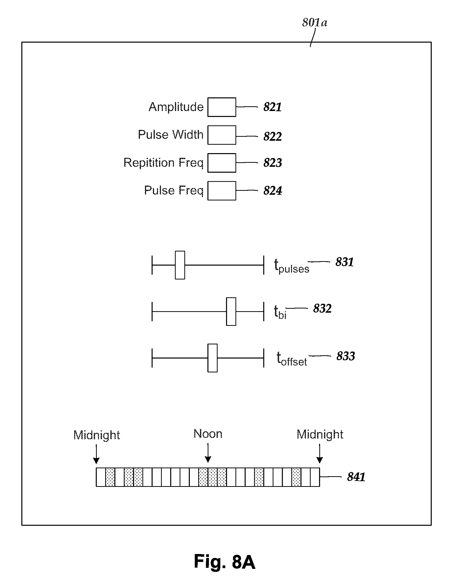
[0032] FIG. 8A is a schematic view of one embodiment of a display with user-selectable controls for adjusting stimulation parameters and time settings for each of the fields collectively, according to the invention;
[0033] FIG. 8B is a schematic view of one embodiment of a display with user-selectable controls for adjusting stimulation parameters and time settings for each of the fields individually, according to the invention;
[0034] FIG. 9A is a schematic view of one embodiment of an overview display with user-selectable controls for adjusting stimulation parameters and time settings for each of the fields collectively, as well as graphical representations of stimulation patterns and fields formed from the selected settings, according to the invention; and
[0035] FIG. 9B is a schematic view of one embodiment of an overview display with user-selectable controls for adjusting stimulation parameters and time settings for each of the fields individually, as well as graphical representations of stimulation patterns and fields formed from the selected settings, according to the invention.
DETAILED DESCRIPTION
[0036] The present invention is directed to the area of electrical stimulation systems and methods of using the systems. The present invention is also directed to systems and methods for enabling a user to control electrical stimulation using multiple stimulation fields.
[0037] Suitable implantable electrical stimulation systems include, but are not limited to, a least one lead with one or more electrodes disposed on a distal end of the lead and one or more terminals disposed on one or more proximal ends of the lead. Leads include, for example, percutaneous leads, paddle leads, cuff leads, or any other arrangement of electrodes on a lead. Examples of electrical stimulation systems with leads are found in, for example, U.S. Pat. Nos. 6,181,969; 6,516,227; 6,609,029; 6,609,032; 6,741,892; 7,244,150; 7,450,997; 7,672,734;7,761,165; 7,783,359; 7,792,590; 7,809,446; 7,949,395; 7,974,706; 8,175,710; 8,224,450; 8,271,094; 8,295,944; 8,364,278; 8,391,985; and 8,688,235; and U.S. Patent Applications Publication Nos. 2007/0150036; 2009/0187222; 2009/0276021; 2010/0076535; 2010/0268298; 2011/0005069; 2011/0004267; 2011/0078900; 2011/0130817; 2011/0130818; 2011/0238129; 2011/0313500; 2012/0016378; 2012/0046710; 2012/0071949; 2012/0165911; 2012/0197375; 2012/0203316; 2012/0203320; 2012/0203321; 2012/0316615; 2013/0105071; and 2013/0197602, all of which are incorporated by reference. In the discussion below, a percutaneous lead will be exemplified, but it will be understood that the methods and systems described herein are also applicable to paddle leads and other leads.
[0038] A percutaneous lead for electrical stimulation (for example, deep brain, spinal cord, peripheral nerve, or cardiac-tissue stimulation) includes stimulation electrodes that can be ring electrodes, segmented electrodes that extend only partially around the circumference of the lead, or any other type of electrode, or any combination thereof. The segmented electrodes can be provided in sets of electrodes, with each set having electrodes circumferentially distributed about the lead at a particular longitudinal position. A set of segmented electrodes can include any suitable number of electrodes including, for example, two, three, four, or more electrodes. For illustrative purposes, the leads are described herein relative to use for deep brain stimulation, but it will be understood that any of the leads can be used for applications other than deep brain stimulation, including spinal cord stimulation, peripheral nerve stimulation, dorsal root ganglion stimulation, sacral nerve stimulation, or stimulation of other nerves, muscles, and tissues.
[0039] Turning to FIG. 1, one embodiment of an electrical stimulation system 10 includes one or more stimulation leads 12 and an implantable pulse generator (IPG) 14. The system 10 can also include one or more of an external remote control (RC) 16, a clinician's programmer (CP) 18, an external trial stimulator (ETS) 20, or an external charger 22.
[0040] The IPG 14 is physically connected, optionally via one or more lead extensions 24, to the stimulation lead(s) 12. Each lead carries multiple electrodes 26 arranged in an array. The IPG 14 includes pulse generation circuitry that delivers electrical stimulation energy in the form of, for example, a pulsed electrical waveform (i.e., a temporal series of electrical pulses) to the electrode array 26 in accordance with a set of stimulation parameters. The implantable pulse generator can be implanted into a patient's body, for example, below the patient's clavicle area or within the patient's buttocks or abdominal cavity. The implantable pulse generator can have eight stimulation channels which may be independently programmable to control the magnitude of the current stimulus from each channel. In some embodiments, the implantable pulse generator can have more or fewer than eight stimulation channels (e.g., 4-, 6-, 16-, 32-, or more stimulation channels). The implantable pulse generator can have one, two, three, four, or more connector ports, for receiving the terminals of the leads and/or lead extensions.
[0041] The ETS 20 may also be physically connected, optionally via the percutaneous lead extensions 28 and external cable 30, to the stimulation leads 12. The ETS 20, which may have similar pulse generation circuitry as the IPG 14, also delivers electrical stimulation energy in the form of, for example, a pulsed electrical waveform to the electrode array 26 in accordance with a set of stimulation parameters. One difference between the ETS 20 and the IPG 14 is that the ETS 20 is often a non-implantable device that is used on a trial basis after the neurostimulation leads 12 have been implanted and prior to implantation of the IPG 14, to test the responsiveness of the stimulation that is to be provided. Any functions described herein with respect to the IPG 14 can likewise be performed with respect to the ETS 20.
[0042] The RC 16 may be used to telemetrically communicate with or control the IPG 14 or ETS 20 via a uni- or bi-directional wireless communications link 32. Once the IPG 14 and neurostimulation leads 12 are implanted, the RC 16 may be used to telemetrically communicate with or control the IPG 14 via a uni- or bi-directional communications link 34. Such communication or control allows the IPG 14 to be turned on or off and to be programmed with different stimulation parameter sets. The IPG 14 may also be operated to modify the programmed stimulation parameters to actively control the characteristics of the electrical stimulation energy output by the IPG 14. The CP 18 allows a user, such as a clinician, the ability to program stimulation parameters for the IPG 14 and ETS 20 in the operating room and in follow-up sessions. Alternately, or additionally, stimulation parameters can be programed via wireless communications (e.g., Bluetooth) between the RC 16 (or external device such as a hand-held electronic device) and the IPG 14.
[0043] The CP 18 may perform this function by indirectly communicating with the IPG 14 or ETS 20, through the RC 16, via a wireless communications link 36. Alternatively, the CP 18 may directly communicate with the IPG 14 or ETS 20 via a wireless communications link (not shown). The stimulation parameters provided by the CP 18 are also used to program the RC 16, so that the stimulation parameters can be subsequently modified by operation of the RC 16 in a stand-alone mode (i.e., without the assistance of the CP 18).
[0044] For purposes of brevity, the details of the RC 16, CP 18, ETS 20, and external charger 22 will not be further described herein. Details of exemplary embodiments of these devices are disclosed in U.S. Pat. No. 6,895,280, which is expressly incorporated herein by reference. Other examples of electrical stimulation systems can be found at U.S. Pat. Nos. 6,181,969; 6,516,227; 6,609,029; 6,609,032; 6,741,892; 7,949,395; 7,244,150; 7,672,734; and 7,761,165; 7,974,706; 8,175,710; 8,224,450; and 8,364,278; and U.S. Patent Application Publication No. 2007/0150036, as well as the other references cited above, all of which are incorporated by reference.
[0045] FIG. 2 illustrates one embodiment of a lead 112 with electrodes 126 disposed at least partially about a circumference of the lead 112 along a distal end portion of the lead and terminals 135 disposed along a proximal end portion of the lead. The lead 112 can be implanted near or within the desired portion of the body to be stimulated such as, for example, the brain, spinal cord, or other body organs or tissues. In one example of operation for deep brain stimulation, access to the desired position in the brain can be accomplished by drilling a hole in the patient's skull or cranium with a cranial drill (commonly referred to as a burr), and coagulating and incising the dura mater, or brain covering. The lead 112 can be inserted into the cranium and brain tissue with the assistance of a stylet (not shown). The lead 112 can be guided to the target location within the brain using, for example, a stereotactic frame and a microdrive motor system. In some embodiments, the microdrive motor system can be fully or partially automatic. The microdrive motor system may be configured to perform one or more the following actions (alone or in combination): insert the lead 112, advance the lead 112, retract the lead 112, or rotate the lead 112.
[0046] In some embodiments, measurement devices coupled to the muscles or other tissues stimulated by the target neurons, or a unit responsive to the patient or clinician, can be coupled to the implantable pulse generator or microdrive motor system. The measurement device, user, or clinician can indicate a response by the target muscles or other tissues to the stimulation or recording electrode(s) to further identify the target neurons and facilitate positioning of the stimulation electrode(s). For example, if the target neurons are directed to a muscle experiencing tremors, a measurement device can be used to observe the muscle and indicate changes in, for example, tremor frequency or amplitude in response to stimulation of neurons. Alternatively, the patient or clinician can observe the muscle and provide feedback.
[0047] The lead 112 for deep brain stimulation can include stimulation electrodes, recording electrodes, or both. In at least some embodiments, the lead 112 is rotatable so that the stimulation electrodes can be aligned with the target neurons after the neurons have been located using the recording electrodes.
[0048] Stimulation electrodes may be disposed on the circumference of the lead 112 to stimulate the target neurons. Stimulation electrodes may be ring-shaped so that current projects from each electrode equally in every direction from the position of the electrode along a length of the lead 112. In the embodiment of FIG. 2, two of the electrodes 126 are ring electrodes 120. Ring electrodes typically do not enable stimulus current to be directed from only a limited angular range around of the lead. Segmented electrodes 130, however, can be used to direct stimulus current to a selected angular range around the lead. When segmented electrodes are used in conjunction with an implantable pulse generator that delivers constant current stimulus, current steering can be achieved to more precisely deliver the stimulus to a position around an axis of the lead (i.e., radial positioning around the axis of the lead). To achieve current steering, segmented electrodes can be utilized in addition to, or as an alternative to, ring electrodes.
[0049] The lead 112 includes a lead body 110, terminals 135, and one or more ring electrodes 120 and one or more sets of segmented electrodes 130 (or any other combination of electrodes). The lead body 110 can be formed of a biocompatible, non-conducting material such as, for example, a polymeric material. Suitable polymeric materials include, but are not limited to, silicone, polyurethane, polyurea, polyurethane-urea, polyethylene, or the like. Once implanted in the body, the lead 100 may be in contact with body tissue for extended periods of time. In at least some embodiments, the lead 112 has a cross-sectional diameter of no more than 1.5 mm and may be in the range of 0.5 to 1.5 mm. In at least some embodiments, the lead 100 has a length of at least 10 cm and the length of the lead 112 may be in the range of 10 to 70 cm.
[0050] The electrodes 126 can be made using a metal, alloy, conductive oxide, or any other suitable conductive biocompatible material. Examples of suitable materials include, but are not limited to, platinum, platinum iridium alloy, iridium, titanium, tungsten, palladium, palladium rhodium, or the like. Preferably, the electrodes are made of a material that is biocompatible and does not substantially corrode under expected operating conditions in the operating environment for the expected duration of use.
[0051] Each of the electrodes can either be used or unused (OFF). When the electrode is used, the electrode can be used as an anode or cathode and carry anodic or cathodic current. In some instances, an electrode might be an anode for a period of time and a cathode for a period of time.
[0052] Deep brain stimulation leads may include one or more sets of segmented electrodes. Segmented electrodes may provide for superior current steering than ring electrodes because target structures in deep brain stimulation are not typically symmetric about the axis of the distal electrode array. Instead, a target may be located on one side of a plane running through the axis of the lead. Through the use of a radially segmented electrode array ("RSEA"), current steering can be performed not only along a length of the lead but also around a circumference of the lead. This provides precise three-dimensional targeting and delivery of the current stimulus to neural target tissue, while potentially avoiding stimulation of other tissue. Examples of leads with segmented electrodes include U.S. Pat. Nos. 8,473,061; 8,571,665; and 8,792,993; U.S. Patent Application Publications Nos. 2010/0268298; 2011/0005069; 2011/0130803; 2011/0130816; 2011/0130817; 2011/0130818; 2011/0078900; 2011/0238129; 2012/0016378; 2012/0046710; 2012/0071949; 2012/0165911; 2012/197375; 2012/0203316; 2012/0203320; 2012/0203321; 2013/0197424; 2013/0197602; 2014/0039587; 2014/0353001; 2014/0358208; 2014/0358209; 2014/0358210; 2015/0045864; 2015/0066120; 2015/0018915; 2015/0051681; U.S. patent applications Ser. Nos. 14/557,211 and 14/286,797; and U.S. Provisional Patent Application Ser. No. 62/113,291, all of which are incorporated herein by reference. Segmented electrodes can also be used for other stimulation techniques including, but not limited to, spinal cord stimulation, peripheral nerve stimulation, dorsal root ganglion stimulation, or stimulation of other nerves, muscles, and tissues.
[0053] FIG. 3 is a schematic overview of one embodiment of components of an electrical stimulation system 300 including an electronic subassembly 310. It will be understood that the electrical stimulation system can include more, fewer, or different components and can have a variety of different configurations including those configurations disclosed in the stimulator references cited herein.
[0054] Some of the components (for example, a power source 312, an antenna 318, a receiver 302, and a processor 304) of the electrical stimulation system can be positioned on one or more circuit boards or similar carriers within a sealed housing of an implantable pulse generator (see e.g., 14 in FIG. 1), if desired. Any power source 312 can be used including, for example, a battery such as a primary battery or a rechargeable battery. Examples of other power sources include super capacitors, nuclear or atomic batteries, mechanical resonators, infrared collectors, thermally-powered energy sources, flexural powered energy sources, bioenergy power sources, fuel cells, bioelectric cells, osmotic pressure pumps, and the like including the power sources described in U.S. Pat. No. 7,437,193, incorporated herein by reference.
[0055] As another alternative, power can be supplied by an external power source through inductive coupling via the optional antenna 318 or a secondary antenna. The external power source can be in a device that is mounted on the skin of the user or in a unit that is provided near the user on a permanent or periodic basis.
[0056] If the power source 312 is a rechargeable battery, the battery may be recharged using the optional antenna 318, if desired. Power can be provided to the battery for recharging by inductively coupling the battery through the antenna to a recharging unit 316 external to the user. Examples of such arrangements can be found in the references identified above.
[0057] The electronic subassembly 310 and, optionally, the power source 312 can be disposed within a control module (e.g., the IPG 14 or the ETS 20 of FIG. 1). The control module is shown in FIG. 4.
[0058] In one embodiment, electrical stimulation signals are emitted by the electrodes 126 on the paddle or lead body to stimulate nerve fibers, muscle fibers, or other body tissues near the electrical stimulation system. The processor 304 is generally included to control the timing and electrical characteristics of the electrical stimulation system. For example, the processor 304 can, if desired, control one or more of the timing, frequency, strength, duration, and waveform of the pulses. In addition, the processor 304 can select which electrodes can be used to provide stimulation, if desired. In some embodiments, the processor 304 selects which electrode(s) are cathodes and which electrode(s) are anodes. In some embodiments, the processor 304 is used to identify which electrodes provide the most useful stimulation of the desired tissue.
[0059] Any processor can be used and can be as simple as an electronic device that, for example, produces pulses at a regular interval or the processor can be capable of receiving and interpreting instructions from an external programming unit 308 that, for example, allows modification of pulse characteristics. In the illustrated embodiment, the processor 304 is coupled to a receiver 302 which, in turn, is coupled to the optional antenna 318. This allows the processor 304 to receive instructions from an external source to, for example, direct the pulse characteristics and the selection of electrodes, if desired.
[0060] In one embodiment, the antenna 318 is capable of receiving signals (e.g., RF signals) from an external telemetry unit 306 which is programmed by the programming unit 308. The programming unit 308 can be external to, or part of, the telemetry unit 306. The telemetry unit 306 can be a device that is worn on the skin of the user or can be carried by the user and can have a form similar to a pager, cellular phone, or remote control, if desired. As another alternative, the telemetry unit 306 may not be worn or carried by the user but may only be available at a home station or at a clinician's office. The programming unit 308 can be any unit that can provide information to the telemetry unit 306 for transmission to the electrical stimulation system 300. The programming unit 308 can be part of the telemetry unit 306 or can provide signals or information to the telemetry unit 306 via a wireless or wired connection. One example of a suitable programming unit is a computer operated by the user or clinician to send signals to the telemetry unit 306.
[0061] The signals sent to the processor 304 via the antenna 318 and the receiver 302 can be used to modify or otherwise direct the operation of the electrical stimulation system. For example, the signals may be used to modify the pulses of the electrical stimulation system such as modifying one or more of pulse duration, pulse frequency, pulse waveform, and pulse strength. The signals may also direct the electrical stimulation system 300 to cease operation, to start operation, to start charging the battery, or to stop charging the battery. In other embodiments, the stimulation system does not include the antenna 318 or receiver 302 and the processor 304 operates as programmed.
[0062] Optionally, the electrical stimulation system 300 may include a transmitter (not shown) coupled to the processor 304 and the antenna 318 for transmitting signals back to the telemetry unit 306 or another unit capable of receiving the signals. For example, the electrical stimulation system 300 may transmit signals indicating whether the electrical stimulation system 300 is operating properly or not or indicating when the battery needs to be charged or the level of charge remaining in the battery. The processor 304 may also be capable of transmitting information about the pulse characteristics so that a user or clinician can determine or verify the characteristics.
[0063] FIG. 4 illustrates one embodiment of a system for practicing the invention. The system can include a computer 400 or any other similar device that includes a processor 402 and a memory 404, a display 406, an input device 408, and, optionally, the electrical stimulation system 412.
[0064] The computer 400 can be a laptop computer, desktop computer, tablet, mobile device, smartphone or other devices that can run applications or programs, or any other suitable device for processing information and for presenting a user interface. The computer can be, for example, a clinician programmer, patient programmer, or remote programmer for the electrical stimulation system 412. The computer 400 can be local to the user or can include components that are non-local to the user including one or both of the processor 402 or memory 404 (or portions thereof). For example, in some embodiments, the user may operate a terminal that is connected to a non-local computer. In other embodiments, the memory can be non-local to the user.
[0065] The computer 400 can utilize any suitable processor 402 including one or more hardware processors that may be local to the user or non-local to the user or other components of the computer. The processor 402 is configured to execute instructions provided to the processor, as described below.
[0066] Any suitable memory 404 can be used for the processor 402. The memory 404 illustrates a type of computer-readable media, namely computer-readable storage media. Computer-readable storage media may include, but is not limited to, nonvolatile, non-transitory, removable, and non-removable media implemented in any method or technology for storage of information, such as computer readable instructions, data structures, program modules, or other data. Examples of computer-readable storage media include RAM, ROM, EEPROM, flash memory, or other memory technology, CD-ROM, digital versatile disks ("DVD") or other optical storage, magnetic cassettes, magnetic tape, magnetic disk storage or other magnetic storage devices, or any other medium which can be used to store the desired information and which can be accessed by a computer.
[0067] Communication methods provide another type of computer readable media; namely communication media. Communication media typically embodies computer-readable instructions, data structures, program modules, or other data in a modulated data signal such as a carrier wave, data signal, or other transport mechanism and include any information delivery media. The terms "modulated data signal," and "carrier-wave signal" includes a signal that has one or more of its characteristics set or changed in such a manner as to encode information, instructions, data, and the like, in the signal. By way of example, communication media includes wired media such as twisted pair, coaxial cable, fiber optics, wave guides, and other wired media and wireless media such as acoustic, RF, infrared, and other wireless media.
[0068] The display 406 can be any suitable display device, such as a monitor, screen, display, or the like, and can include a printer. The input device 408 can be, for example, a keyboard, mouse, touch screen, track ball, joystick, voice recognition system, or any combination thereof, or the like and can be used by the user to interact with a user interface or clinical effects map.
[0069] The electrical stimulation system 412 can include, for example, a control module 414 (for example, an implantable pulse generator) and a lead 416 (for example, the lead illustrated in FIG. 1.) The electrical stimulation system 412 may communicate with the computer 400 through a wired or wireless connection or, alternatively or additionally, a user can provide information between the electrical stimulation system 412 and the computer 400 using a computer-readable medium or by some other mechanism. In some embodiments, the computer 400 may include part of the electrical stimulation system.
[0070] In at least some instances, a treating physician may wish to tailor the stimulation parameters (such as which one or more of the stimulating electrode contacts to use, the stimulation pulse amplitude (such as current or voltage amplitude depending on the stimulator being used,) the stimulation pulse width, the stimulation frequency, or the like or any combination thereof) for a particular patient to improve the effectiveness of the therapy. Electrical stimulation systems can provide a user interface that facilitates parameter selections. Examples of such systems and interfaces can be found in, for example, U.S. Pat. Nos. 8,326,433; 8,831,731; 8,849,632; 9,050,470; and 9,072,905; and U.S. Patent Application Publication No. 2014/0277284, all of which are incorporated herein by reference in their entireties.
[0071] Turning to FIG. 5A, conventional stimulation may involve generating a single stimulation field for each lead, such that all electrical pulses emitted from the lead do so at the same time. The stimulation field is typically generated to stimulate as many targeted neurons as feasible, while also avoiding stimulation of as many untargeted neurons as feasible.
[0072] At least some neurological conditions (e.g., Parkinsonism, essential tremor, dystonia, or the like) involve populations of neurons in the brain that become overactive. Such over-activity may involve pathological synchronous firings of action potentials along affected parenchymal populations.
[0073] Although the invention is not limited to any particular theory, it is thought that electrical stimulation can be used to desynchronize action potential firings along at least some neurons of the affected neuron population. For example, asynchronous stimulation can be used to produce a coordinated reset of synchronous action potential firings.
[0074] One way to provide asynchronous stimulation is to stimulate neurons using multiple stimulation fields. In some instances, the electrodes of one or more leads are used to generate a series of stimulation fields ("fields"), where each field is generated by a different subset of electrodes (although the subsets may be overlapping). Each field has a set of stimulation parameters (e.g., frequency, pulse width, and the like). The stimulation parameters for each field can be either the same or different from the remaining fields. In at least some embodiments, the period for two different stimulation fields are temporally offset from one another. The difference in stimulation timing may reduce, or even prevent, undesired neuronal synchronization. Each field stimulates different subpopulations of neurons with or without temporal or physical overlap with one or more other fields.
[0075] The electrodes can either be in close physical proximity to one another, or physically spaced-apart from one another. The electrodes may be disposed along a single implanted lead, or along multiple implanted leads. When multiple leads are utilized, the multiple leads may be coupled to the same control module, or to separate control modules in communication with one another (to coordinate the stimulation timing or stimulation parameters). The electrodes may be implanted at the same target stimulation location or along two different target stimulation locations within the patient. In at least some embodiments, the two or more electrodes are implanted within the patient's brain.
[0076] It is thought, although not necessary to the invention, that the electrical stimulation signals generated by the two or more electrodes generate effective electric fields (e.g., electrical stimulation propagating from the electrodes sufficient to cause an excitatory effect on axons surrounding the electrodes) that function to reset the undesired neural activity in a coordinated manner.
[0077] The electrodes may employ the same stimulation parameters, or may have one or more different stimulation parameters. The size and shape of the effective electric fields generated by the electrodes is based on the set of stimulation parameters used to generate the stimulation. In at least some instances, the size and shape of the effective electric fields generated by the two or more electrodes (or sets of electrodes) at a given set of stimulation parameters can be estimated, using one or more computer models (e.g., Volume of Tissue Activated Model, Stimulation Field Model, or the like or combinations thereof). In at least some embodiments, the effective volume of an electric field can be based on the region of tissue that experiences a stimulating effect in response to the electric field. Outside this effective volume, the electric field may be too weak to stimulate the tissue. Although sub-threshold stimulation may also provide some effects, the computer models may facilitate selection of implantation locations, or facilitate selection of stimulation parameters, or both. Examples of methods for determining the volume of activation can be found in, for example, U.S. Pat. Nos. 7,346,282; 8,180,601; 8,209,027; 8,326,433; 8,589,316; 8,594,800; 8,606,360; 8,675,945; 8,831,731; 8,849,632; 8.958,615; 9.020,789; and U.S. Patent Application Publications Nos. 2009/0287272; 2009/0287273; 2012/0314924; 2013/0116744; 2014/0122379; 2015/0066111; and 2016/0030749, all of which are incorporated herein by reference.
[0078] In some embodiments, the electrodes generate effective electric fields that are temporally offset (e.g., time-delayed) from one another so that the effective electric fields are out of phase from one another. In at least some embodiments, the electrodes are situated such the effective electric fields generated by the electrodes stimulate different populations of neurons in communication with one another (e.g., different neurons along a particular neural pathway). Although not wishing to be bound by a particular theory, the offsetting of the effective electric fields generated by the electrodes may be such that the downstream neurons are in a refractory period while the upstream neurons are propagating action potentials. In which case, the action potentials may be unable to propagate from the upstream neurons to the downstream neurons. Accordingly, undesired synchronized neuronal activity may be disrupted.
[0079] Any suitable time delay may be implemented between the electrodes. In some embodiments, the time delay may be determined by testing and observation. In some embodiments, the time delay is determined based on the frequency of the undesired neural activity (e.g., an observed shifted theta-band frequency) to be desynchronized or disrupted.
[0080] When the generated effective electric fields are time-delayed from one another, in some embodiments it may be desirable for the different electric fields to have little or no physical overlap. This may facilitate coordination the resetting of the action potential propagation by stimulating different populations of cells that are in communication with one another. When there is substantial physical overlap of effective electric fields between the electrodes, the stimulation parameters of the electrodes may be varied from one another in order to preferentially target some neurons more than others.
[0081] It has been shown that some stimulation parameters may preferentially target some neurons more than others. At least some physical characteristics of neurons (e.g., axon diameters, the presence or absence of a myelin sheath, or the like) may affect whether or not those neurons are excited by an effective electric field having a particular set of stimulation parameters. Consequently, in at least some embodiments, the stimulation parameters of at least one of the generated effective electric fields is varied in response to one or more physical characteristics of the neurons along the overlapping portion of the generated effective electric fields (e.g., axon diameters, the presence or absence of a myelin sheath, or the like).
[0082] The different stimulation parameters may enable a first set of stimulation parameters of a first electrode (or set of electrodes) to stimulate a first set of target neurons and a second set of stimulation parameters of a second electrode (or set of electrodes) to stimulate a second set of target neurons. In some embodiments, the second set of target neurons is a subset of the first set of target neurons. In which case, one narrow example of a stimulation procedure may include only a portion of the overall population of neurons within an overlapping portion of the effective electric fields becoming excitable during stimulation by a first electrode (or set of electrodes) with a first set of stimulation parameters, while all (or nearly all) of the overall population of neurons within the overlapping portion of the effective electric fields becoming excitable during stimulation by a second electrode with a second set of stimulation parameters.
[0083] In other embodiments, the second set of target neurons is mutually exclusive of the first set of target neurons. In which case, one example of a stimulation procedure may include a first portion of the overall population of neurons within an overlapping portion of the effective electric fields becoming excitable during stimulation by a first electrode (or set of electrodes) with a first set of stimulation parameters, and a second portion (mutually exclusive of the first portion) of the overall population of neurons within the overlapping portion of the effective electric fields becoming excitable during stimulation by a second electrode (or set of electrodes) with a second set of stimulation parameters.
[0084] In at least some embodiments, stimulation can be timed between the two or more electrodes such that some neurons are in a refractory period while other neurons are propagating action potentials. In which case, at least some of the action potentials are unable to propagate along the entire length of the neural pathway. Accordingly, undesired neural activity may be disrupted through desynchronization.
[0085] FIG. 5A shows one example of a series of repeating stimulation patterns generated by multiple stimulation fields ("fields") over a period of time. The illustrated embodiment includes a graphical depiction of stimulation patterns from each of four different fields: Field 1 507, Field 2 508, Field 3 509, and Field 4 510 graphed over time 512. In the illustrated embodiment, each of the four fields is generated using the same stimulation parameters. In alternate embodiments, one or more of the fields is generated using different stimulation parameters than at least one other field.
[0086] The illustrated stimulation patterns, each field includes a repeating stimulation-pattern time interval (T.sub.sp) 520, which includes a first time-interval (t.sub.pulses) 524 over which a series of pulses are emitted at a particular frequency (f.sub.pulses) 526, followed by a second time-interval (t.sub.inactivity) 530 when no pulses are emitted (i.e., a period of inactivity). For each particular field, the stimulation pattern is temporally-adjusted from the remaining fields by a time interval such that the series of pulses for a particular field (i.e., the first time-interval) occurs during the periods of inactivity (i.e., the second time-interval) of each of the remaining fields. For example, in the illustrated embodiment the beginning of the series of pulses for Field 2 508 is temporally-adjusted from the beginning of the series of pulses for Field 1 507 by an amount of time (t.sub.offset) 534. And during the first time-interval 524 for Field 1 507, each of Field 2 508, Field 3 509, and Field 4 510 are in the second time-interval 530.
[0087] From an initial temporal starting point 537, each of the fields is temporally-adjusted from the remaining fields by a period of time (t.sub.delay) 539 that is a multiple of the amount of time (t.sub.offset) 534. For example, Field 2 508 is temporally-adjusted from the beginning of the series of pulses for Field 1 507 by a (t.sub.delay) 539 equal to (t.sub.offset) 534, while Field 3 509 is temporally-adjusted from the beginning of the series of pulses for Field 1 507 by a (t.sub.delay) 539 equal to two times (t.sub.offset) 534, and Field 4 510 is temporally-adjusted from the beginning of the series of pulses for Field 1 507 by a (t.sub.delay) 539 equal to three times (t.sub.offset) 534.
[0088] The stimulation-pattern time intervals 520 can be either the same or different for each of the fields. The first time-interval 524 can be either the same or different for each of the fields. The second time-interval 530 can be either the same or different for each of the fields.
[0089] The second time-interval (t.sub.inactivity) 530 can include an inter-pulse time delay between the end of a series of pulses from one field and the beginning of the series of pulses from the next most closely temporally-offset field. In the illustrated embodiment, the beginning of the series of pulses for Field 3 509 is offset from the end of the series of pulses for Field 2 508 by inter-pulse time delay (t.sub.iptd) 540. In the illustrated embodiment, the time interval t.sub.burst 550 refers to the time interval over which the series of pulses occur (t.sub.pulses) 524 plus the inter-pulse time delay (t.sub.iptd) 540. In other words, t.sub.burst=t.sub.pulses+t.sub.iptd, where t.sub.iptd is the time interval during a "burst" when the field is "inactive". In the illustrated embodiment, the period of time t.sub.burst 550 is shown as occurring from the beginning of a series of pulses from Field 2 508 to the beginning of a series of pulses from Field 3 509.
[0090] FIG. 5A shows the stimulation fields arranged into a set of repeating time blocks: Block 1 560, Block 2 561, Block 3 562. Each time block is of equal duration and has a time duration that is equal in length to the stimulation-pattern time intervals (T.sub.sp) 520. Each time block includes a single series of pulses (i.e., a first time-interval 524) for each of the stimulation fields. The blocks occur at a repetition frequency (f.sub.repetition) 565, which can be user-adjustable via the user interface (see e.g., 455 in FIG. 4).
[0091] In FIG. 5A, each pulse of a given series of pulses is shown as a vertical line, or spike. The spikes shown FIG. 5A are idealized representations of pulses. Actual pulses may include more complex waveforms. FIG. 5B shows one embodiment of a possible waveform 570 suitable for use in lieu of any one of the spikes shown in FIG. 5A.
[0092] A user interface can be used to generate and control stimulation patterns. Certain rules can be applied to limit a range of user-selectable values, based on the stimulation patterns described in FIG. 5A. For example, the maximum time duration for t.sub.burst 550 is T.sub.sp 520/N, where Nis the number of fields. Additionally, since t.sub.burst 550=t.sub.pulses 524+t.sub.iptd 540, t.sub.iptd 540 must be less than T.sub.sp/N.
[0093] Turning to FIG. 5C, the graphical depiction of repeating stimulation patterns (blocks) shown in FIG. 5A represents a portion of a "micro-schedule" of stimulation patterns. Micro-schedules, in turn, typically occur as part of a larger "macro-schedule" of stimulation patterns. Micro-schedules may, for example, define a particular stimulation session, while macro-schedules may define when stimulation sessions are to occur (e.g, once every fifteen minutes, once an hour, twice a day, three days a week, or the like).
[0094] FIG. 5C shows the series of repeating stimulation patterns of each of four different fields: Field 1 507, Field 2 508, Field 3 509, and Field 4 510 graphed over time 512. Note that in FIG. 5C, the first time-intervals (524 in FIG. 5A) over which a series of pulses are emitted are shown as cross-hatched rectangles instead of a series of spikes, for clarity of illustration.
[0095] In FIG. 5C, the stimulation patterns are shown over a period of time that is longer than the period of time depicted in FIG. 5A. A micro-schedule 581 includes at least one micro ON period of time 583 (represented in FIG. 5A as a repeating stimulation-pattern time interval (T.sub.sp) 520, or a block), where stimulation occurs. A micro ON period of time 583 may be any suitable length of time, but is typically in the millisecond or second range of time. Typically, a stimulation session (described below) includes multiple repeating micro ON period of time 583 (e.g., stimulation-pattern time intervals). When multiple micro ON period of time 583 are used, each micro-schedule 581 also includes a micro OFF period of time 585 occurring after the micro ON period of time 583 until the last successive micro ON period of time 583 occurs. Stimulation does not occur during the micro OFF period of time 585. A macro-schedule 591 is a period of time that includes a stimulation session 593 followed by a macro OFF period of time 595 over which no stimulation occurs. A macro OFF period of time 595 can be any suitable length of time (e.g., minutes, hours, days, weeks, or the like)
[0096] In the embodiments shown in FIGS. 5A and 5C, Field 1 507, Field 2 508, Field 3 509, and Field 4 510 stimulate in the same order during each micro ON period of time 583. In at least some embodiments, the ordering of the stimulation occurring by different fields during micro ON periods of time 583 can be shuffled. Shuffling the order of stimulation may be beneficial to therapy. The ordering of the stimulation can be reshuffled at particular intervals of time (e.g., every block, after a particular number of milliseconds, after a particular number of seconds, or the like). As described below, a user interface can include one or more controls for activating a field shuffling feature and for defining an interval of shuffling. Any suitable type of shuffling can be implemented. For example, the shuffling can be random, sequential, user-defined, or other type of shuffling.
[0097] Turning to FIG. 6A, in at least some embodiments each of the stimulation fields can be manually defined. A user interface can be used to provide a way for a user to define the stimulation fields individually, collectively, or both. The user interface includes user-selectable controls for adjusting the number of stimulation fields. In at least some embodiments, the user interface includes user-selectable controls for adjusting one or more field settings (e.g., which electrodes are used, whether or not current is adjusted axially or radially, the locations of the stimulation fields relative to the lead, or the like). In at least some embodiments, the user interface includes a graphical representation of one or more leads and electrodes disposed along the lead(s).
[0098] FIGS. 6A-6D show a display 601 with graphical representations of a distal portion of a lead 612' and corresponding electrodes 626'. The display 601 also includes user-selectable controls for defining fields obtainable from the electrodes 626'. Different user selections are included in each of FIGS. 6A-6D.
[0099] A user-controllable field-span indicator 657 is disposed along an electrode-containing portion of the lead 612'. The field-span indicator 657 enables a user to select the length, as well as the placement, of the span for one or more generated fields and the electrodes used to generate the field(s). The user can slide endpoints 658a and 658b to select a particular set of electrodes from which fields are generated, or a particular location along the length of the lead where one or more fields are desired. In FIGS. 6A-6D, the span is oriented axially with respect to the graphical representation of a lead 612'. In FIGS. 6A and 6B, the span covers a span of four electrodes 626'. In FIG. 6C, the span covers two electrodes. In FIG. 6D, the span covers six electrodes.
[0100] A user-selectable field control 661 enables a user to select the number of fields to be generated within the selected span. In the embodiment illustrated in FIGS. 6A and 6B, a user-selected value of "4" has been entered. In FIG. 6C, a user-selected value of "3" has been entered. In FIG. 6D, a user-selected value of "12" has been entered.
[0101] The fields are distributed along the spans. The user-controllable field-span indicator 657 includes a distribution center control 659 for selecting a position for the distribution center of the selected number of fields along the selected span. In FIGS. 6A, 6C, and 6D, the distribution center is set to a "center" of the selected span. In FIG. 6B, the distribution center is "off-center" along the span. In at least some embodiments, a span may include multiple distribution centers that can be selected by a user. FIG. 6D shows three user-adjustable distribution center controls 659a, 659b, 659c.
[0102] FIGS. 6E-6F show one embodiment of differences in field centers between a distribution center set to a "center" of a span compared to an off-center distribution center. FIG. 6E shows field centers, such as field center 663, for the fields of FIG. 6A, where the distribution center is set to the "center" of the span. As shown in FIG. 6E, the four field centers are equally spaced-apart along the span 657. FIG. 6F shows field centers, such as field center 663, for the fields of FIG. 6B, where the distribution center is off-center. As shown in FIG. 6F, the four field centers are unequally spaced-apart along the span 657.
[0103] Linear interpolation may be used to distribute the fields along the span. In at least some embodiments, field fractionalizations are generated by algorithm rather than by programmer. In at least some embodiments, fields specified by a programmer are mapped onto the user interface.
[0104] Turning to FIGS. 7A-7B, the user interface may include one or more user-selectable controls 702 for selecting between a linear (axial) set of settings of field parameters and a directional (radial) set of settings of field parameters. In some embodiments, a user can toggle between different displays, with each display being dedicated to either a linear (axial) set of settings of field parameters or a directional (radial) set of settings of field parameters. In other embodiments, a user can integrate linear and directions settings in a single display.
[0105] In FIGS. 6A-6D, the electrodes are ring-shaped. Stimulation energy emitted from ring-shaped electrodes is typically distributed evenly around a circumference of the lead. Accordingly, each field may extend around the entire circumference of the lead. Thus, while the stimulation energy can be adjusted axially, it is typically not adjustable circumferentially (i.e., radially) around a lead. When, however, electrode arrays include segmented electrodes, multiple fields can be generated circumferentially around the lead in lieu of, or in addition to, one or more linear fields.
[0106] FIGS. 7A-7B show a display 701 with a graphical representation of a distal portion of a lead 712' and corresponding electrodes 726'. A user-controllable field-span indicator 757 is disposed along an electrode-containing portion of the lead 712'.
[0107] The lead 712' and electrodes 726' are shown in two orientations. In FIG. 7A, the 712' and electrodes 726' are shown in side view, whereas in FIG. 7B, the lead 712' and electrodes 726' are shown in transverse cross-sectional view. In FIG. 7A, the span is oriented axially with respect to the lead 712', and the distribution center control 659 is adjustable linearly along the span. In FIG. 7B, the span is oriented radially with respect to the lead 712', and the distribution center control 759 is adjustable circumferentially along the span.
[0108] A user-selectable field control 761a enables a user to select the number of fields to be generated along the selected linear span. In the embodiment illustrated in FIG. 7A, a user-selected value of "4" has been entered. In FIG. 7B, a user-selectable field control 761b enables a user to select the number of fields to be generated along the selected circumferential span. In the embodiment illustrated in FIG. 7B, a user-selected value of "3" has been entered. When segmented electrodes are used, the total number of fields would typically be the number of linear fields multiplied by the number of circumferential fields. When fields are generated solely from ring electrodes, then there is only a linear component and there is no circumferential component.
[0109] Turning to FIGS. 8A-8B, the user interface may include user-selectable controls for adjusting one or more stimulation parameters for each field, either separately or collectively. FIG. 8A shows a display 801a with user-selectable controls for selecting a general setting for making selections for each of the fields at once. In the illustrated embodiment, the user interface includes user-selectable controls 821-824 that enable a user to select values for different stimulation parameters, such as amplitude 821, pulse width 822, first frequency (see e.g., 565 in FIG. 5A) 823, and second frequency (see e.g., 526 in FIG. 5A) 824.
[0110] The user interface may include user-selectable temporal-adjustment controls for adjusting different time intervals, time delays, time offsets, or the like, for one or more fields, individually or collectively. In the illustrated embodiment, the user interface includes user-selectable controls 831-833 that enable a user to adjust the duration of time intervals, such as the first time-interval over which a series of pulses are emitted (see e.g., 524 in FIG. 5A) 831, the inter-pulse time delay (see e.g., 540 in FIG. 5A) 832, and the timing offset between different fields (see e.g., 534 in FIG. 5A) 833.
[0111] The user interface may include user-selectable temporal-adjustment controls for adjusting the timing of the repeating stimulation patterns at the micro-schedule level or over the macro-schedule level. For example, it may be desired for one or more fields to stimulate over some timing blocks, but not others. As another example, it may be desired for one or more fields to stimulate during some hours of the day, but not others. In the illustrated embodiment, the user interface includes a user-selectable control 841 that enables a user to select, for one or more fields, whether or not to stimulate over each hour of the day. It will be understood that other increments of time are possible in lieu of, or in addition to, hour increments (e.g., one minute, five minutes, ten minute, fifteen minutes, thirty minutes, two hours, four hours, or the like)
[0112] Additionally, or alternatively, the user interface may enable a user to select the same variables as described in FIG. 8A for each field individually. FIG. 8B shows a display 801b with user-selectable controls for selecting a general setting for making selections for each of the fields individually. In the illustrated embodiment, four fields 812-815 are available for selection. In at least some embodiments, the number of available fields is based on the number of fields available. Any suitable number of fields can be selected based on user selection or other technique.
[0113] In the illustrated embodiment, the user interface includes user-selectable controls 821-824 that enable a user to select values for different stimulation parameters, such as amplitude 821, pulse width 822, repetition frequency (see e.g., 565 in FIG. 5A) 823, and pulse frequency (see e.g., 526 in FIG. 5A) 824.
[0114] The user interface may include user-selectable temporal-adjustment controls for adjusting different time intervals for one or more fields, individually or collectively. In the illustrated embodiment, the user interface includes user-selectable controls 831-833 that enable a user to adjust the duration of time intervals, such as the first time-interval over which a series of pulses are emitted (see e.g., 524 in FIG. 5A) 831, the inter-pulse time delay (see e.g., 540 in FIG. 5A) 832, and the timing offset between different fields (see e.g., 534 in FIG. 5A) 833.
[0115] The user interface may include user-selectable temporal-adjustment controls for adjusting the timing of the repeating stimulation patterns for the fields over a period of time equal to or greater than the stimulation-pattern time interval. For example, it may be desired for one or more fields to stimulate over some timing blocks, but not others. As another example, it may be desired for one or more fields to stimulate during some hours of the day, but not others. In the illustrated embodiment, the user interface includes a user-selectable control 841 that enables a user to select, for one or more fields, whether or not to stimulate over each hour of the day.
[0116] Turning to FIGS. 9A-9B, the user interface may include a display that provides an overview of previously-selected settings and one or more graphical representations of the generated fields, or stimulation patterns, or both. FIG. 9A shows a display 901a with a graphical representation 902 of the stimulation patterns after making selections for each of the fields collectively. The illustrated embodiment shows the stimulation patterns for four fields over three timing blocks. Each of the stimulation patterns in the illustrated embodiment are identical to one another except for a time delay between each of the fields. The user interface may include one or more stimulation-parameter settings of the graphical representations of the stimulation patterns. The illustrated embodiment shows values entered for the repetition frequency (see e.g., 565 in FIG. 5A) 823 and pulse frequency (see e.g., 526 in FIG. 5A) 824.
[0117] The user interface may include one or more graphical representations of the stimulation fields 911-914 disposed around one or more graphical representations of leads positioned in one or more orientations. The illustrated embodiment shows, for each field, a graphical representation of a stimulation field disposed around a graphical representation of a lead in both side view and transverse cross-sectional view.
[0118] The illustrated embodiment also includes several different user-selectable temporal-adjustment controls for adjusting the timing of the repeating stimulation patterns. Control 921 shows user-selected ratios for the timing blocks being in an "ON" position (i.e., stimulating) to the timing blocks being in an "OFF" position (i.e., not stimulating). In other words, the control 921 enables a user to select a repeating pattern of stimulation at the timing-block level (e.g., micro-schedule). Control 921 is selected for all of the fields collectively.
[0119] Control 931 also shows user-selected ratios of timing blocks being "ON" and "OFF". Control 931, however, shows selected repeating pattern of stimulation over a period of hours rather than over a period of timing blocks (e.g., macro-schedule). Control 931 is set for all of the fields collectively.
[0120] Control 941 enables a user to activate a field shuffle for shuffling the ordering of stimulation by the different fields. The time interval between successive reshuffles can also be user-selected (e.g., every block, after a particular number of milliseconds, after a particular number of seconds, or the like). In FIG. 9A, the time interval of reshuffling is shown as being based on a selectable number of blocks. Any suitable type of shuffling can be implemented. For example, the shuffling can be random, sequential, user-defined, or other type of shuffling. Selection of the type of shuffling can be pre-selected or user-selected, and can be performed on the display 901a, or via another device. In alternate embodiments, a slider other type of control, can be used to enable a user to select the time interval between successive reshuffles.
[0121] Additionally, or alternatively, the user interface may enable a user to select the same variables as described in FIG. 9A for each field individually. FIG. 9B shows a display 901b with a graphical representation 902 of the stimulation patterns after making selections for each of the fields collectively. The illustrated embodiment shows the stimulation patterns for four fields over three timing blocks. Each of the stimulation patterns in the illustrated embodiment are identical to one another except for a time delay between each of the fields. The user interface may include one or more stimulation-parameter settings of the graphical representations of the stimulation patterns. The illustrated embodiment shows values entered for the repetition frequency (see e.g., 565 in FIG. 5A) 823 and pulse frequency (see e.g., 526 in FIG. 5A) 824 for each individual field.
[0122] The user interface may include one or more graphical representations of the stimulation fields 911-914 disposed around one or more graphical representations of leads positioned in one or more orientations. The illustrated embodiment shows, for each field, a graphical representation of a stimulation field disposed around a graphical representation of a lead in both side view and transverse cross-sectional view.
[0123] The illustrated embodiment also includes several different user-selectable temporal-adjustment controls for adjusting the timing of the repeating stimulation patterns. Control 921 shows user-selected ratios for the timing blocks being in an "ON" position (i.e., stimulating) to the timing blocks being in an "OFF" position (i.e., not stimulating). In other words, the control 921 enables a user to select a repeating pattern of stimulation at the timing-block level. Control 921 is selected individually for each of the fields.
[0124] Control 931 also shows user-selected ratios of timing blocks being "ON" and "OFF". Control 931, however, shows selected repeating pattern of stimulation over a period of hours rather than over a period of timing blocks. Control 931 is set individually for each of the fields.
[0125] Control 941 enables a user to activate a field shuffle for shuffling the ordering of stimulation by the different fields. The time interval between successive reshuffles can also be user-selected (e.g., every block, after a particular number of milliseconds, after a particular number of seconds, or the like). In FIG. 9B, the time interval of reshuffling is shown as being based on a selectable number of blocks. Any suitable type of shuffling can be implemented. For example, the shuffling can be random, sequential, user-defined, or other type of shuffling. Selection of the type of shuffling can be pre-selected or user-selected, and can be performed on the display 901a, or via another device. In alternate embodiments, a slider other type of control, can be used to enable a user to select the time interval between successive reshuffles.
[0126] The computer program instructions can be stored on any suitable computer-readable medium including, but not limited to, RAM, ROM, EEPROM, flash memory or other memory technology, CD-ROM, digital versatile disks ("DVD") or other optical storage, magnetic cassettes, magnetic tape, magnetic disk storage or other magnetic storage devices, or any other medium which can be used to store the desired information and which can be accessed by a computing device.
[0127] The above specification and examples provide a description of the manufacture and use of the invention. Since many embodiments of the invention can be made without departing from the spirit and scope of the invention, the invention also resides in the claims hereinafter appended.
* * * * *
D00000
D00001
D00002
D00003
D00004
D00005
D00006
D00007
D00008
D00009
D00010
D00011
D00012

XML
uspto.report is an independent third-party trademark research tool that is not affiliated, endorsed, or sponsored by the United States Patent and Trademark Office (USPTO) or any other governmental organization. The information provided by uspto.report is based on publicly available data at the time of writing and is intended for informational purposes only.
While we strive to provide accurate and up-to-date information, we do not guarantee the accuracy, completeness, reliability, or suitability of the information displayed on this site. The use of this site is at your own risk. Any reliance you place on such information is therefore strictly at your own risk.
All official trademark data, including owner information, should be verified by visiting the official USPTO website at www.uspto.gov. This site is not intended to replace professional legal advice and should not be used as a substitute for consulting with a legal professional who is knowledgeable about trademark law.