Beverage Container Having Non-Circular Shape
Novak; Michael A. ; et al.
U.S. patent application number 15/895432 was filed with the patent office on 2019-02-21 for beverage container having non-circular shape. The applicant listed for this patent is Decision Basis Consulting, LLC. Invention is credited to Benjamin C. Danker, Christopher M. Novak, Michael A. Novak.
| Application Number | 20190053649 15/895432 |
| Document ID | / |
| Family ID | 65359896 |
| Filed Date | 2019-02-21 |


View All Diagrams
| United States Patent Application | 20190053649 |
| Kind Code | A1 |
| Novak; Michael A. ; et al. | February 21, 2019 |
Beverage Container Having Non-Circular Shape
Abstract
A beverage container having an oval or elliptical cross-sectional shape is provided. The beverage container comprises a beverage receptacle comprising a cavity surrounded by a container wall configured to store a liquid and an open top portion. The beverage container further comprises a lid configured to be attached to the open top portion of the beverage receptacle to cover the open top portion of the beverage receptacle and comprising an opening formed through the lid configured to dispense the liquid. The lid and at least the open top portion of the beverage receptacle comprise an oval or elliptical shape to provide the beverage container with its oval or elliptical cross-sectional shape. The oval or elliptical shape of the beverage container is configured to improve visibility of a user during use of the beverage container.
| Inventors: | Novak; Michael A.; (Woodbury, CT) ; Novak; Christopher M.; (Woodbury, CT) ; Danker; Benjamin C.; (Branford, CT) | ||||||||||
| Applicant: |
|
||||||||||
|---|---|---|---|---|---|---|---|---|---|---|---|
| Family ID: | 65359896 | ||||||||||
| Appl. No.: | 15/895432 | ||||||||||
| Filed: | February 13, 2018 |
Related U.S. Patent Documents
| Application Number | Filing Date | Patent Number | ||
|---|---|---|---|---|
| 62458330 | Feb 13, 2017 | |||
| Current U.S. Class: | 1/1 |
| Current CPC Class: | B65D 43/022 20130101; B65D 2543/00629 20130101; B65D 2543/00888 20130101; B65D 53/02 20130101; B65D 81/3869 20130101; B65D 2543/00731 20130101; B65D 2543/00398 20130101; B65D 2543/00083 20130101; B65D 43/267 20130101; B65D 47/286 20130101; B65D 2543/00046 20130101; B65D 2543/00796 20130101; B65D 2543/00296 20130101; B65D 23/102 20130101; A47G 19/2288 20130101; B65D 2543/005 20130101; B65D 2543/00685 20130101; A47G 19/2266 20130101; B65D 47/06 20130101; B65D 2543/00555 20130101; B65D 43/0212 20130101; B65D 2543/00509 20130101; A47G 19/2272 20130101; B65D 2543/00537 20130101; B65D 47/0847 20130101 |
| International Class: | A47G 19/22 20060101 A47G019/22; B65D 81/38 20060101 B65D081/38; B65D 47/28 20060101 B65D047/28; B65D 43/02 20060101 B65D043/02; B65D 43/26 20060101 B65D043/26; B65D 53/02 20060101 B65D053/02; B65D 23/10 20060101 B65D023/10 |
Claims
1. A beverage container comprising: a beverage receptacle comprising: a cavity surrounded by a container wall configured to store a liquid and, an open top portion; and a lid configured to be attached to the open top portion of the beverage receptacle to cover the open top portion of the beverage receptacle and comprising an opening formed therethrough configured to dispense the liquid; wherein the lid and at least the open top portion of the beverage receptacle comprise an oval shape to provide the beverage container with an oval cross-sectional shape configured to improve visibility of a user during use of the beverage container.
2. The beverage container according to claim 1, further comprising a plate configured to seal the opening in the lid from the cavity of the beverage container to prevent liquid from being dispensed from the beverage container.
3. The beverage container according to claim 2, wherein the lid further comprises a slot configured to receive a first end of a bar, wherein the bar comprises a second end affixed to a trigger, and wherein actuating the trigger is configured to unseal the opening in the lid from the cavity of the beverage container.
4. The beverage container according to claim 3, wherein the first end of the bar is a beveled end and the plate comprises a raised surface positioned adjacent to the beveled end of the bar; and wherein the actuation of the trigger causes the beveled end to slide over the raised surface of the plate and depress the plate towards the cavity to unseal the opening in the lid from the cavity of the beverage container.
5. The beverage container according to claim 4, further comprising a spring arranged between a wall in the slot and the first end of the bar, wherein the spring is configured to exert a biasing force against the bar and trigger when the trigger is released to seal the opening in the lid from the cavity of the beverage container.
6. The beverage container according to claim 5, wherein the lid comprises a base section; and wherein the plate is configured to be received within the base section of the lid and comprises one or more sealing gaskets arranged around the plate.
7. The beverage container according to claim 6, wherein the plate further comprises a cover portion configured to be received in the opening of the lid when the plate is in a closed position sealing the opening in the lid from the cavity of the beverage container.
8. The beverage container according to claim 1, further comprising a valve configured to seal the opening in the lid from the cavity of the beverage container to prevent the liquid from being dispensed from the beverage container.
9. The beverage container according to claim 8, wherein the valve comprises: a flexible valve dome configured in a first position to seal the opening in the lid from the cavity; a valve stem affixed to the valve dome; and a valve actuator affixed to the valve stem.
10. The beverage container according to claim 9, wherein the lid further comprises a lever having a first end with a slot or opening configured to receive the valve stem and a second end affixed to a trigger.
11. The beverage container according to claim 10, wherein actuating the trigger is configured to cause the lever to lift the valve actuator, inverting the valve dome to a second position to unseal the opening in the lid from the cavity of the beverage container.
12. The beverage container according to claim 11, wherein releasing the trigger is configured to cause the valve dome to return to the first position to seal the opening in the lid from the cavity of the beverage container.
13. The beverage container according to claim 12, wherein the valve is made of a rubber material.
14. The beverage container according to claim 1, wherein the container wall comprises an outer wall and an inner wall with an insulation layer formed therebetween, and wherein the cavity is formed within the inner wall.
15. The beverage container according to claim 14, wherein at least a top portion of the outer wall and at least a top portion of the inner wall comprise an oval shape.
16. The beverage container according to claim 15, wherein the lid comprises a base section comprising one or more sealing gaskets configured to be received in the top portion of the inner wall to attach the lid to the beverage receptacle.
17. The beverage container according to claim 1, wherein the beverage container is made of a paper material and wherein the lid comprises one or more ribs molded into the lid.
18. The beverage container according to claim 1, wherein a base portion of the beverage receptacle has a circular cross-sectional shape.
19. The beverage container according to claim 1, wherein the lid and at least the open top portion of the beverage receptacle comprise an elliptical shape to provide the beverage container with an elliptical cross-sectional shape.
20. The beverage container according to claim 3, wherein the trigger is arranged to the left or right side of an axis of symmetry of the lid passing through the opening in the lid.
Description
CROSS-REFERENCE TO RELATED APPLICATIONS
[0001] The present application claims the benefit of U.S. Provisional Application No. 62/458,330 filed Feb. 13, 2017, which is hereby incorporated by reference in its entirety.
BACKGROUND OF THE INVENTION
[0002] The current marketplace features many travel beverage containers to allow a consumer to drink a beverage, such as coffee or tea, while on the go. Current travel beverage containers take user safety into account in a few manners. In addition to the dangers of burns that a spilled hot beverage can cause, there is the idea that a driver could take their eyes off the road, even for a short moment in order to address the concern of a spill on their person or the interior of the vehicle. Design features are provided to address this concern by making the container spill or leak-proof, such as providing automatic locking, press-to-open, gaskets and stable forms. Travel containers should also be designed for one-handed use, allowing the user to open, close and drink from a beverage container with one hand, while allowing the user to still safely operate a vehicle. These actions should be simple and elegant, and not require any additional attention taking mind of the road.
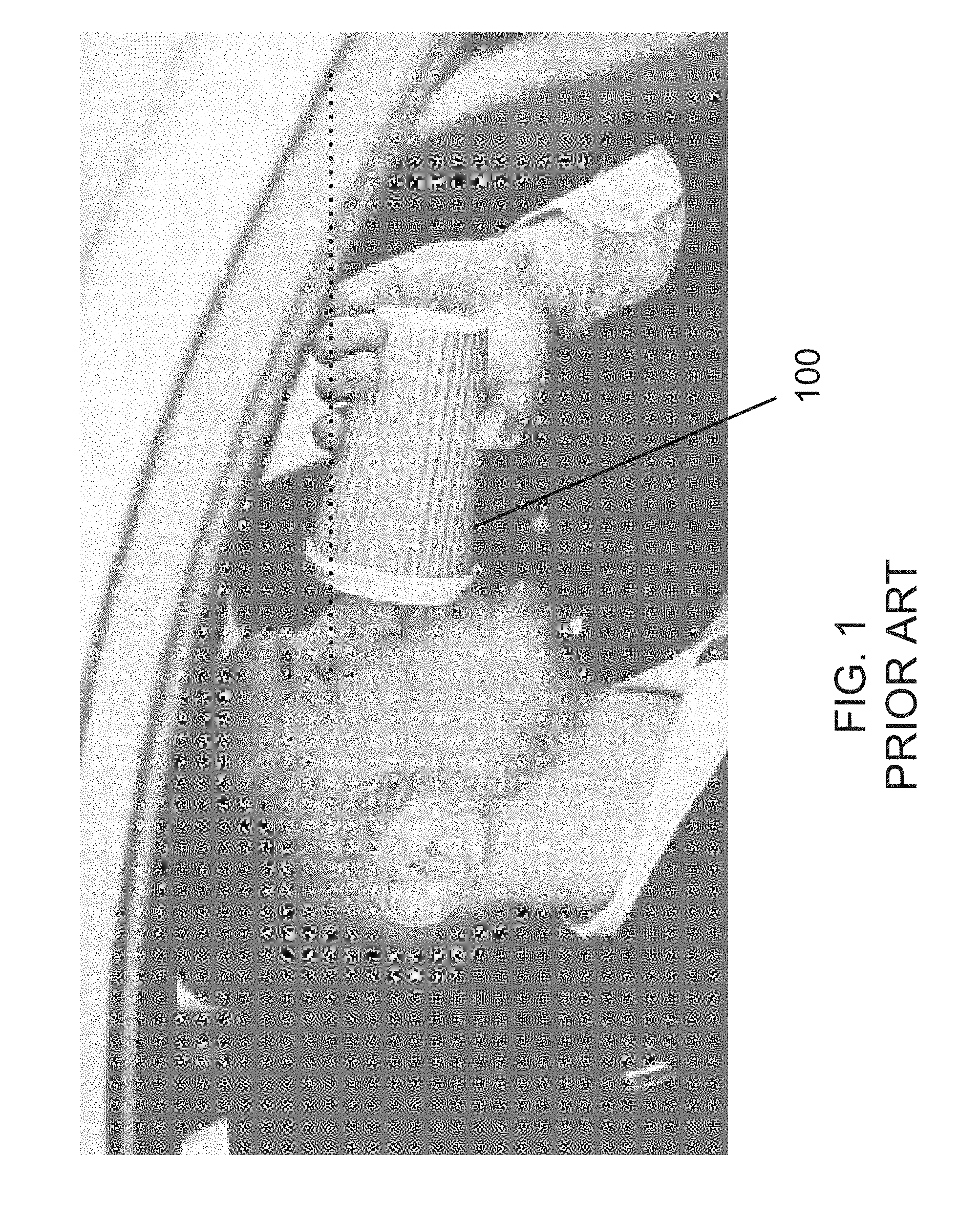
[0003] However, many design attributes of existing containers aim to prevent problems a user may face, but do not address a major concern that exists while driving, which is that drinking from a container while driving limits the user's field of view by obstructing his or her visual path to the road. This is shown for example in the beverage container 100 in FIG. 1. It is one of many causes of distraction while driving. The tilt needed, especially as the beverage container 100 is nearing being empty, requires the driver to lift the container to a point which blocks a vast majority, if not the entirety, of the user's field of view. As the volume or size of the container increases, the problem is exacerbated. In 2014, 3,179 people were killed and 431,000 injured in motor vehicle crashes involving distracted drivers.
[0004] The present invention seeks to provide a beverage container that increases visibility for the user without limiting features that have come to be expected by the consumer. It is an object of the present invention to provide a travel beverage container for beverages such as coffee or tea, that makes up for the deficiencies in the art by taking into consideration the field of view of the user while driving, ultimately creating a safer and more thoughtful consumer experience.
SUMMARY OF THE INVENTION
[0005] The present invention solves the shortcomings of the art by providing a beverage container that transitions the shape from circular to a more pinched oval or ellipse as the container progresses towards the lid. This dramatically increases visibility during use, while allowing the vessel to sit inside standard cup holders and maintain stability when standing on a table or surface. The present invention includes travel beverage containers in disposable and non-disposable form.
[0006] In accordance with the present invention, a beverage container is provided comprising a beverage receptacle comprising a cavity surrounded by a container wall configured to store a liquid and, an open top portion and further comprising a lid configured to be attached to the open top portion of the beverage receptacle to cover the open top portion of the beverage receptacle and comprising an opening formed therethrough configured to dispense the liquid. The lid and at least the open top portion of the beverage receptacle comprise an oval shape to provide the beverage container with an oval cross-sectional shape configured to improve visibility of a user during use of the beverage container.
[0007] In accordance with an embodiment of the present invention, the beverage container may further comprise a plate configured to seal the opening in the lid from the cavity of the beverage container to prevent liquid from being dispensed from the beverage container. The lid may further comprise a slot configured to receive a first end of a bar, wherein the bar comprises a second end affixed to a trigger, and wherein actuating the trigger is configured to unseal the opening in the lid from the cavity of the beverage container. The first end of the bar may be a beveled end and the plate comprises a raised surface positioned adjacent to the beveled end of the bar, such that the actuation of the trigger causes the beveled end to slide over the raised surface of the plate and depress the plate towards the cavity to unseal the opening in the lid from the cavity of the beverage container. The beverage container may further comprise a spring arranged between a wall in the slot and the first end of the bar, and the spring is configured to exert a biasing force against the bar and trigger when the trigger is released to seal the opening in the lid from the cavity of the beverage container. The lid may comprise a base section, and the plate may be configured to be received within the base section of the lid and may comprise one or more sealing gaskets arranged around the plate. The plate may further comprise a cover portion configured to be received in the opening of the lid when the plate is in a closed position sealing the opening in the lid from the cavity of the beverage container. In certain embodiments of the beverage container, the bar and the trigger can be arranged to the left or right side of an axis of symmetry of the lid passing through the opening in the lid.
[0008] In accordance with a further embodiment of the beverage container of the present invention, the beverage container may further comprise a valve configured to seal the opening in the lid from the cavity of the beverage container to prevent the liquid from being dispensed from the beverage container. The valve may comprise a flexible valve dome configured in a first position to seal the opening in the lid from the cavity, a valve stem affixed to the valve dome and a valve actuator affixed to the valve stem. The lid may further comprise a lever having a first end with a slot or opening configured to receive the valve stem and a second end affixed to a trigger. Actuating the trigger is configured to cause the lever to lift the valve actuator, inverting the valve dome to a second position to unseal the opening in the lid from the cavity of the beverage container, and releasing the trigger is configured to cause the valve dome to return to the first position to seal the opening in the lid from the cavity of the beverage container. In an embodiment of the beverage container of the present invention, the valve is made of a rubber material. In certain embodiments of the beverage container, the lever and the trigger can be arranged to the left or right side of an axis of symmetry of the lid passing through the opening in the lid.
[0009] In a further embodiment of the beverage container of the present invention, which may include one or more of the above-referenced embodiments, the container wall comprises an outer wall and an inner wall with an insulation layer formed therebetween, and wherein the cavity is formed within the inner wall. At least a top portion of the outer wall and at least a top portion of the inner wall comprise an oval shape. In certain embodiments of the beverage container, the lid may comprise a base section comprising one or more sealing gaskets configured to be received in the top portion of the inner wall to attach the lid to the beverage receptacle.
[0010] In accordance with a further embodiment of the beverage container of the present invention, the beverage container is made of a paper material and the lid comprises one or more ribs molded into the lid.
[0011] In a further embodiment of the beverage container of the present invention, which may include one or more of the above-referenced embodiments, a base portion of the beverage receptacle has a circular cross-sectional shape.
[0012] In a further embodiment of the beverage container of the present invention, which may include one or more of the above-referenced embodiments, the lid and at least the open top portion of the beverage receptacle comprise an elliptical shape to provide the beverage container with an elliptical cross-sectional shape.
BRIEF DESCRIPTION OF THE FIGURES
[0013] FIG. 1 shows the use of a beverage container according to the prior art.
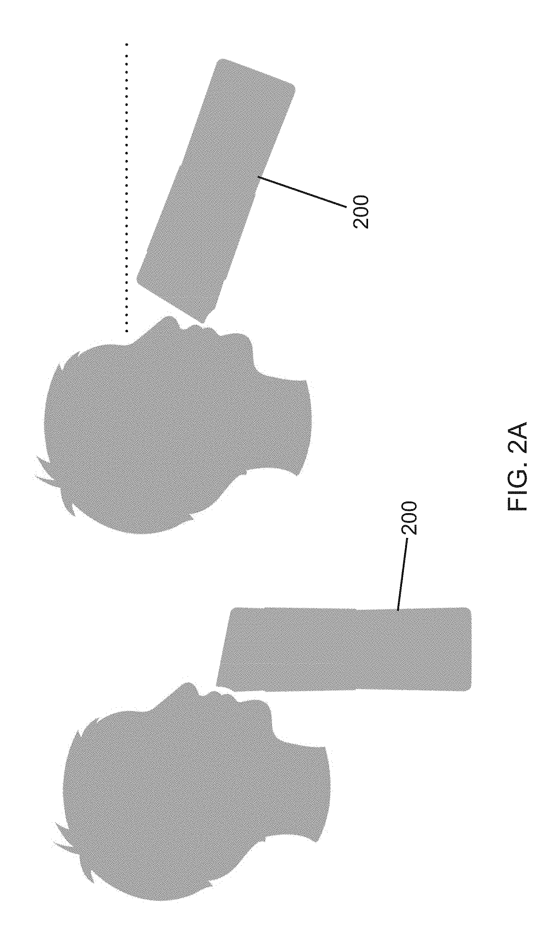
[0014] FIG. 2A shows an example of the visibility increase resulting from a beverage container in accordance with the present invention.
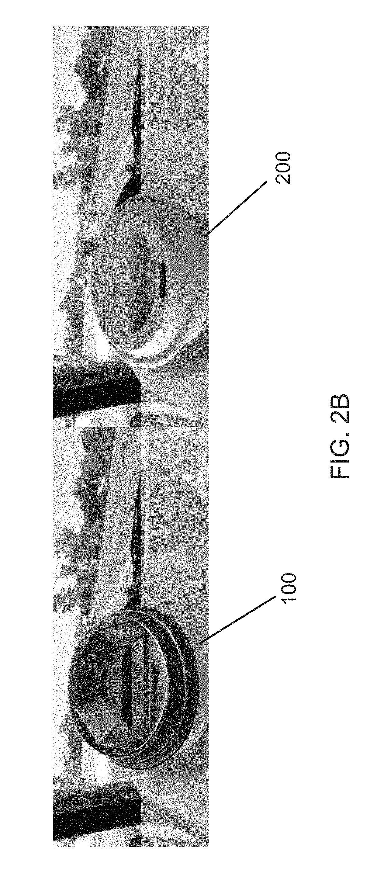
[0015] FIG. 2B shows an example illustration of the difference in field of view to a user when using a beverage container in accordance with the present invention (image on the right side) as compared to using a beverage container according to the prior art (image on the left side).
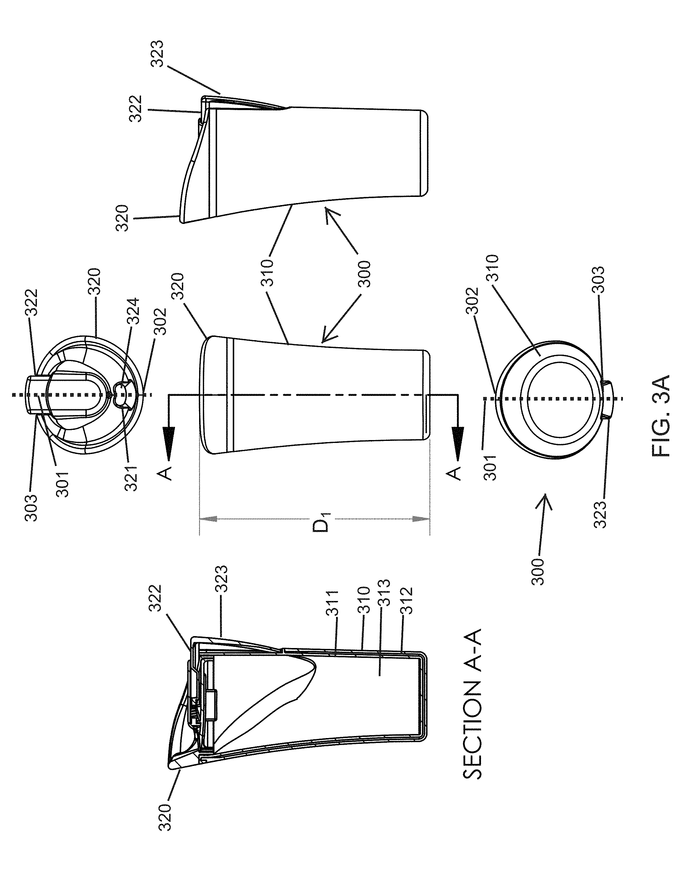
[0016] FIG. 3A shows various views of a beverage container according to a first embodiment of the present invention, including a top side view, a bottom side view, a front side view, a right side view, and a cross-sectional view along axis A-A.
[0017] FIG. 3B shows a perspective view of the beverage container according to the first embodiment of the present invention.
[0018] FIG. 3C shows a cross-sectional view of the beverage container according to the first embodiment of the present invention.
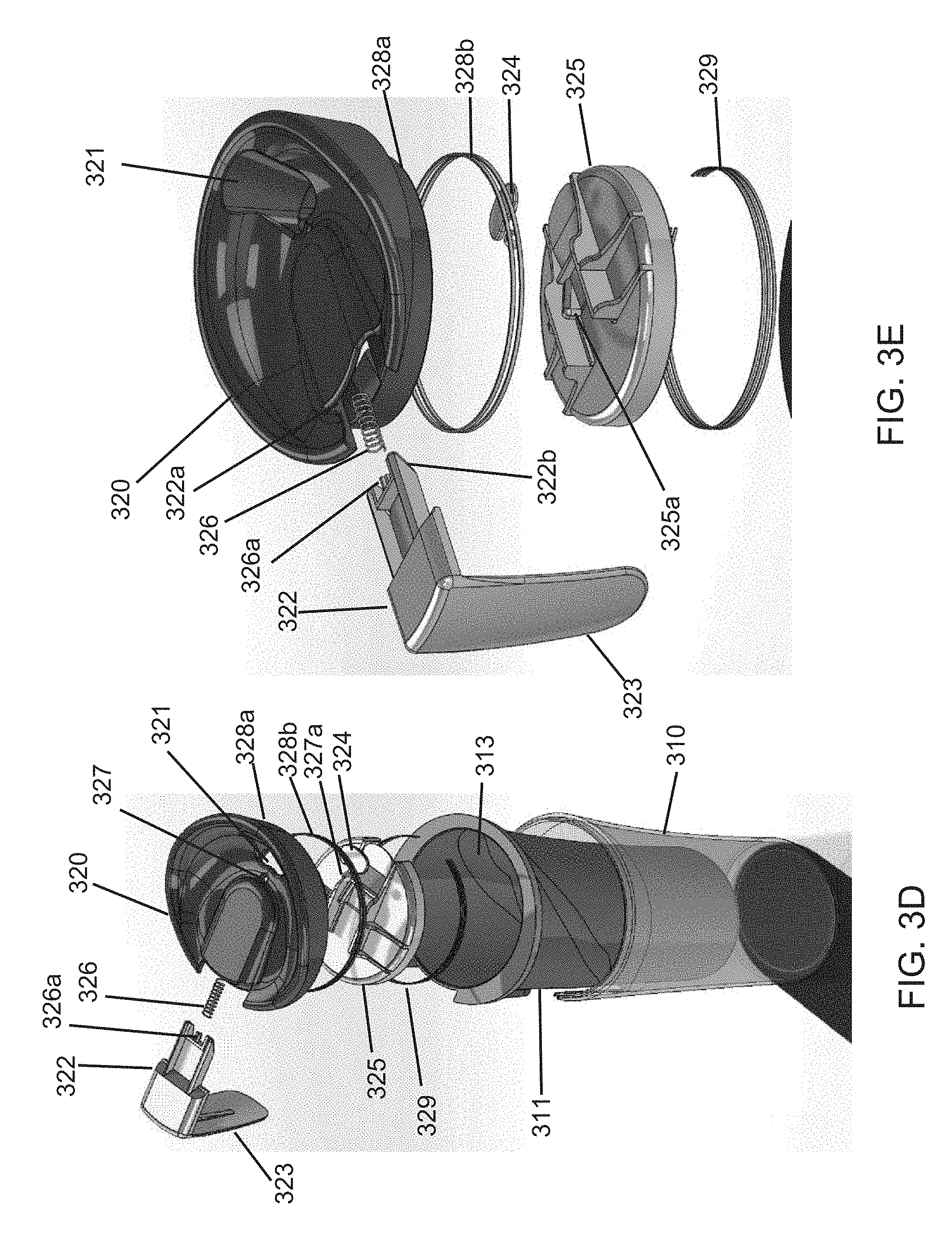
[0019] FIG. 3D shows an exploded view of the beverage container according to the first embodiment of the present invention.
[0020] FIG. 3E shows an exploded view of a lid of the beverage container according to the first embodiment of the present invention.
[0021] FIGS. 3F-3J show various views of lids of the beverage container according to the first embodiment of the present invention.
[0022] FIG. 4A shows a beverage container according to a second embodiment of the present invention.
[0023] FIG. 4B shows various views of the beverage container according to the second embodiment of the present invention, including a top side view, a bottom side view, a front side view, a right side view, a left side view and a cross-sectional view along axis A-A.
[0024] FIG. 4C shows a valve for the beverage container according to the second embodiment of the present invention,
[0025] FIGS. 4D-4E show various views of the beverage container according to the second embodiment of the present invention.
[0026] FIG. 4F shows a cross-sectional view of the beverage container according to the second embodiment of the present invention.
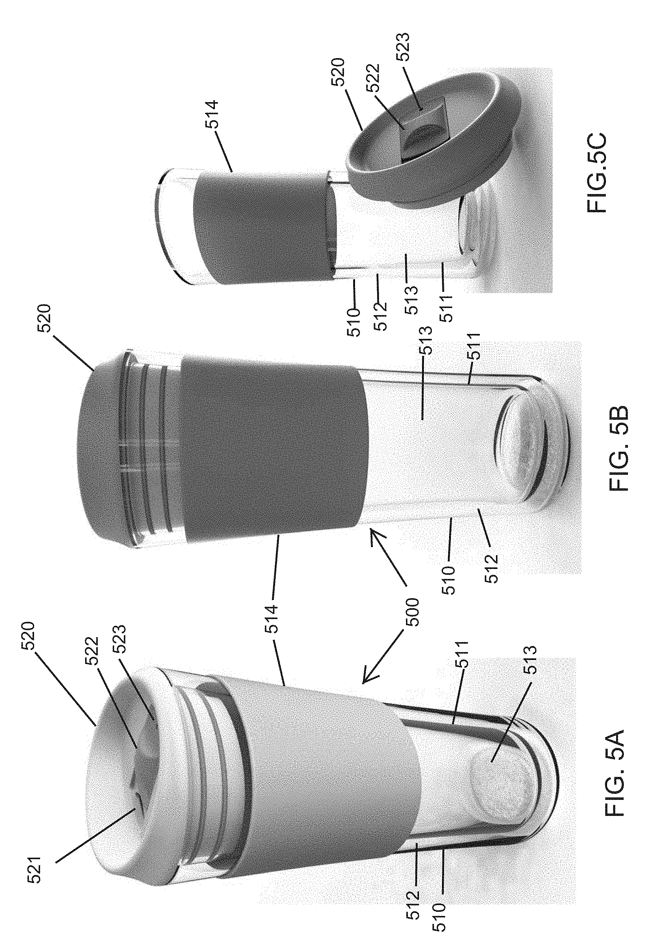
[0027] FIGS. 5A-5C show various views of the beverage container according to a third embodiment of the present invention.
[0028] FIG. 5D shows various further views of the beverage container according to the third embodiment of the present invention, including a top side view, a bottom side view, a front side view, a right side view, a left side view and a cross-sectional view along axis A-A.
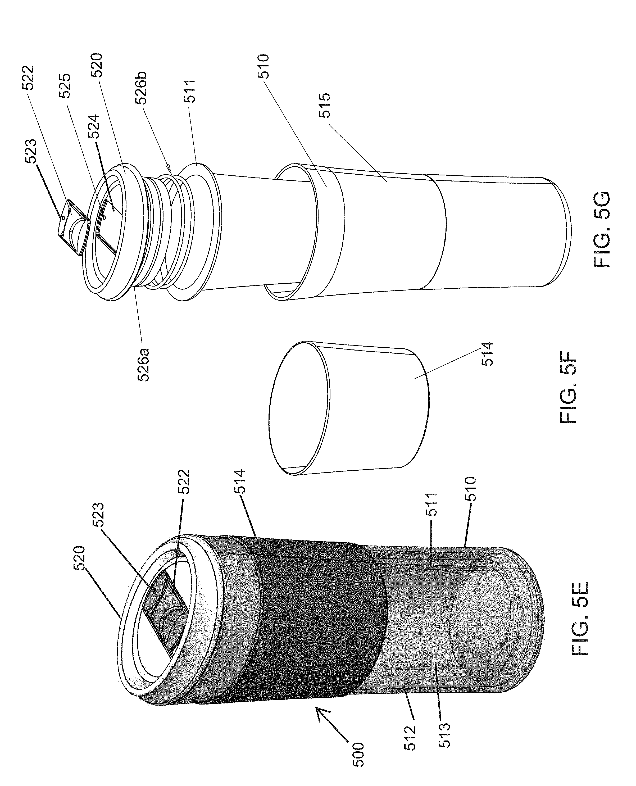
[0029] FIG. 5E shows a perspective view of the beverage container according to the third embodiment of the present invention.
[0030] FIG. 5F shows a grip for the beverage container according to the third embodiment of the present invention.
[0031] FIG. 5G shows an exploded view of the beverage container according to the third embodiment of the present invention.
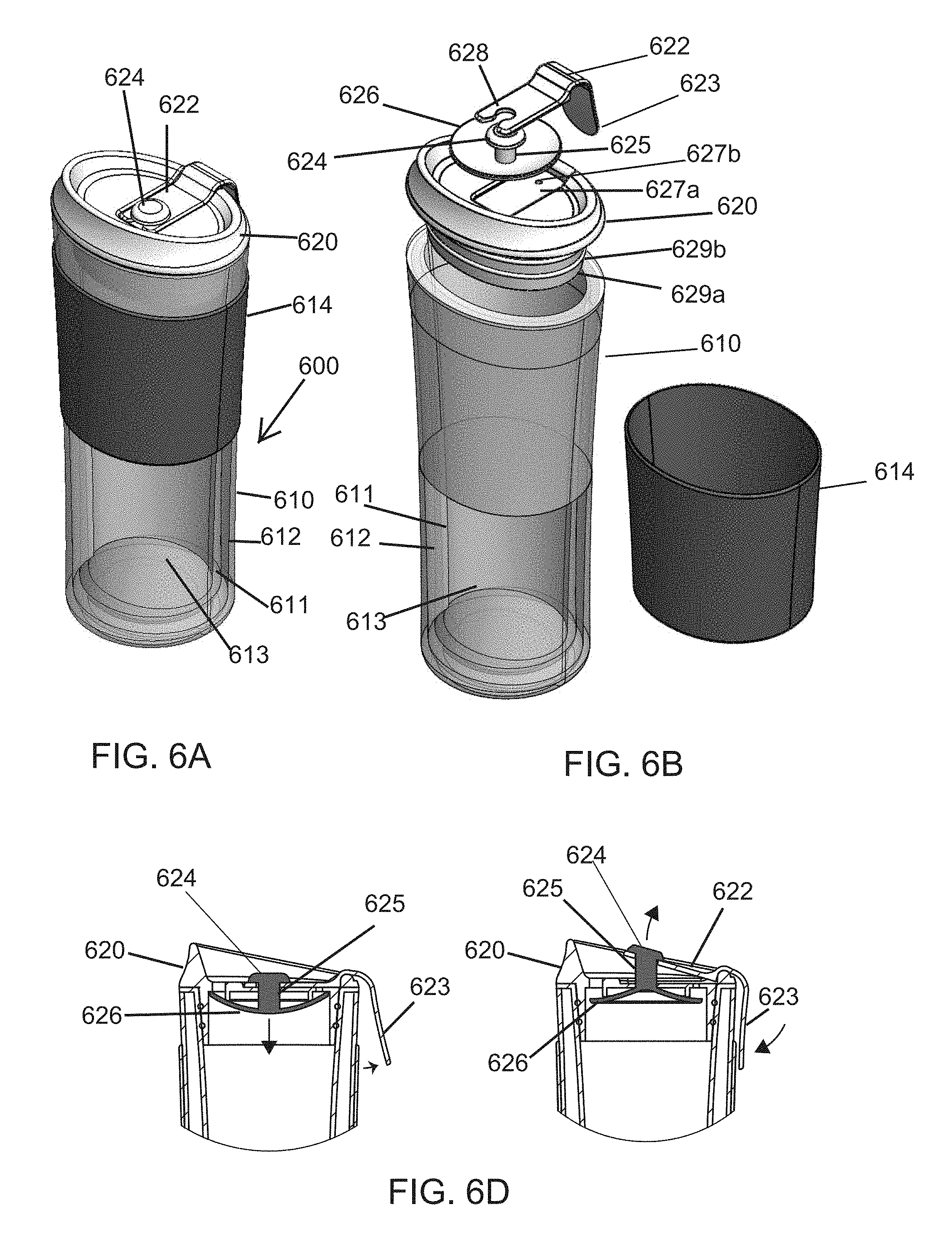
[0032] FIG. 6A shows a perspective view of a beverage container according to a fourth embodiment of the present invention.
[0033] FIG. 6B shows an exploded view of the beverage container according to the fourth embodiment of the present invention.
[0034] FIG. 6C shows various views of the beverage container according to the fourth embodiment of the present invention, including a top side view, a bottom side view, a front side view, a right side view, and a back side view.
[0035] FIG. 6D shows the opening and closing of a valve of the beverage container of the fourth embodiment of the present invention.
[0036] FIGS. 7A-7C show various views of a beverage container according to a fifth embodiment of the present invention.
[0037] FIG. 7D shows various further views of the beverage container according to the fifth embodiment of the present invention, including a top side view, a bottom side view, a front side view, a right side view, and a left side view.
[0038] FIG. 8A shows a beverage container according to a sixth embodiment of the present invention.
[0039] FIG. 8B shows various views of the beverage container according to the sixth embodiment of the present invention, including a top side view, a bottom side view, a front side view and a right side view.
[0040] FIGS. 9A-9C show various views of a beverage container according to a seventh embodiment of the present invention.
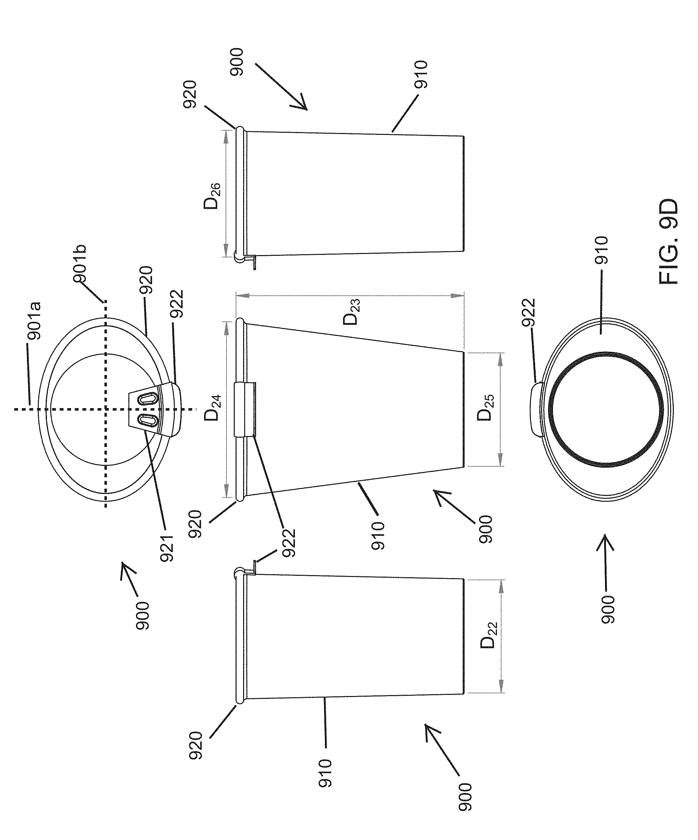
[0041] FIG. 9D shows various further views of the beverage container according to the seventh embodiment of the present invention, including a top side view, a bottom side view, a front side view, a right side view, and a left side view.
DETAILED DESCRIPTION OF THE FIGURES
[0042] The present invention will now be described, with reference made to FIGS. 2A-9D.
[0043] FIG. 2A shows an example of the visibility increase resulting from a beverage container 200 in accordance with the present invention. FIG. 2B shows an example illustration of the difference in field of view to a user when using a beverage container 200 in accordance with the present invention compared to a using beverage container 100 according to the prior art. By pinching the cross-section of the container, the user's field of view is not obstructed by the beverage container.
[0044] FIGS. 3A-9D show various embodiments of beverage containers according to the present invention, at least a portion of which has an oval or non-circular cross-section, which results in a pinched shape to improve visibility while drinking. The beverage container of the present invention comprises a shape in which the lid and at least an upper portion of the beverage container wall are oval or elliptical. As used herein, "ellipse" or "elliptical" is intended to refer to an ellipse or an elliptical shape that is not a circle, and "oval" may to refer to a shape having two axes of symmetry, such as an ellipse, or having one axis of symmetry, as understood by those of skill in the art.
[0045] The container can be made from any material known in the art that is used in beverage containers, including various plastic or metal materials. In certain embodiments, the beverage container may be made from transparent materials to further aid the user's visibility through the beverage container. The beverage containers of the present invention may also be configured to hold various volumes of liquid, and are not limited to any particular volume or dimensions.
[0046] Several embodiments of the invention may include a valve mechanism in the lid of the container for opening and closing the container, as shown for example in FIGS. 4A-4F and 6A-6D. The valve mechanism includes a dome, made of rubber or another flexible material, attached to a lever. The dome includes a projection, which attaches the dome to the lever, by snapping the lever onto the projection, for example. When the lever is actuated, it flexes the dome upward, causing the container to open and allow the beverage contents to exit the container. When the lever is released, the dome reverts back to its original form and closes the container. It is further noted that this valve mechanism and other container opening mechanisms described herein and shown in FIGS. 3A-9D can be used in combination with containers other than those shown in the Figures and does not require the container have a non-circular shape. For example, the valve mechanism comprising the dome and lever as in FIGS. 4A-4F and 6A-6D may be used in combination with beverage containers known in the art, including those with a circular shape.
[0047] Various additional, exemplary features of the inventions are illustrated and described in the embodiments shown in FIGS. 3A-9D.
[0048] FIGS. 3A-3 show a first embodiment of a beverage container 300 according to the present invention.
[0049] The overall shape of the outer perimeter of the beverage container 300 is non-circular, as shown for example in the top side and bottom side views of the beverage container 300 in FIG. 3A. In particular, the beverage container 300 has an oval shape defined by the lid 320 and at least a top portion of the outer wall 310, having a single axis of symmetry 301. A first section 302 of the perimeter of the lid 320, adjacent to the opening 321 of the beverage container 300, is curved and has a first radius of curvature. A second section 303 of the perimeter of the lid 320, opposite the opening 321 of the beverage container 300, is flattened and has a second radius of curvature that is greater than the first radius of curvature. The flattened, second section 303 is opposite the opening 321, such that during use of the beverage container 300, there is less obstruction in the user's line of vision. Although the cross-sectional shape at the top of the beverage container 300 defined by the lid 320 and top portion of the outer wall 310 are non-circular, the outer wall 310 may taper as it approaches the base of the beverage container 300 such that the base of the beverage container 300 may have a circular cross-section, allowing the beverage container 300 to fit in a standard cup holder.
[0050] The beverage container 300 includes a lid 320 configured to be received in and attachable to a receptacle comprising an outer wall 310. The receptacle comprises an outer wall 310 and an inner wall 311. An insulating layer 312 is provided in between the outer wall 310 and inner wall 311 and the inner wall 311 surrounds a cavity 313 formed therein configured to receive a beverage. The insulating layer 312 may comprise a vacuum or may be filled with an insulating material, and is sealed by sealing or connecting the outer wall 310 and inner wall 311 at the top of the beverage container 300. The insulating layer 312 is configured to aid in maintaining the temperature of a hot or cold beverage in the cavity 313. In certain embodiments, the outer wall 310 may also comprise a grip to assist a user in gripping the beverage container 300.
[0051] The lid 320 of the beverage container 300 comprises an opening 321 formed therethrough that allows any beverage in the cavity 313 to be dispensed from the beverage container 300. The lid 320 also comprises an opening mechanism that is configured to keep the opening 321 closed and provide a seal between the cavity 313 and opening 321 when the beverage container 300 is not in use or the user does not intend to dispense a beverage.
[0052] A bar 322 is provided on a top surface of the lid 320 and comprises a trigger 323 that extends over an edge of the lid 320. The opening 321 is sealed in a closed position by a cover 324 that is dimensioned and shaped to fit into the opening 321. The cover 324 is affixed to a plate 325 that is arranged directly beneath the lid 320, in between the lid 320 and the cavity 313 so as to form a seal between the cavity 313 and the lid 320 when the beverage container 300 is in a closed position. The lid 320 comprises a slot 322a that is configured to house a beveled end 322b of the bar 322. A spring 326 is provided in the slot 322a, with one end of the spring 326 attached to a projection 326a on the bar 322 and the other end of the spring 326 attached to a projection 326b in the slot 322a. The bar 322 is arranged within the slot 322a such that when the beverage container 300 is in a closed position, the beveled end 322b of the bar 322 is positioned adjacent to a raised surface 325a on the plate 325.
[0053] When the trigger 323 is squeezed by the user towards the opening 321 of the beverage container 300, the bar 322 is pushed towards the opening 321. Movement of the bar 322 towards the opening 321 causes the beveled end 322b of the bar 322 to also move towards the opening 321, and the beveled end 322b slides over the raised surface 325a of the plate 325. This causes the plate 325 to be depressed downward, away from the opening 321 and towards the cavity 313, thereby breaking the seal between the cavity 313 and the opening 321 and allowing a beverage in the cavity 313 to be dispensed from the opening 321. When in the opened position, a vent hole plug 327a affixed to the plate 325 is also repositioned, such that an air vent hole 327 on the lid 320 is also opened. To return the beverage container 300 to the closed position, the trigger 323 can be released, and the force of the spring 326 biases the bar 322 back to its original position, allowing the plate 325 and cover 324 to return to their original positions, closing the opening 321.
[0054] The lid 320 has an oval shape and is configured to be secured to the receptacle of the beverage container 300 by inserting the lid 320 into the cavity 313 defined by the inner wall 311, which also has a corresponding oval shape at least at a top portion of the inner wall 311. In an exemplary embodiment of the beverage container 300, the lid 320 comprises one or more sealing gaskets 328b arranged around a base section 328a of the lid 320, which is configured to be inserted into the cavity 313 and secured to the inner wall 311 in a manner that seals any beverage in the cavity 313. The base section 328a of the lid is also configured to receive and house the plate 325. The plate 325 may comprise one or more sealing gaskets 329 around the perimeter of the plate 325 to provide a seal between the base section 328a of the lid 320 and the plate 325, which prevents the beverage from being dispensed out of the opening 321 when the beverage container 300 is in a closed position.
[0055] In the embodiment of the beverage container 300 shown in FIGS. 3A-3I, the beverage container may have a height (D.sub.1) of approximately 7 inches. However, the dimensions of the beverage container 300 may vary in alternative embodiments without departing from the scope of the invention.
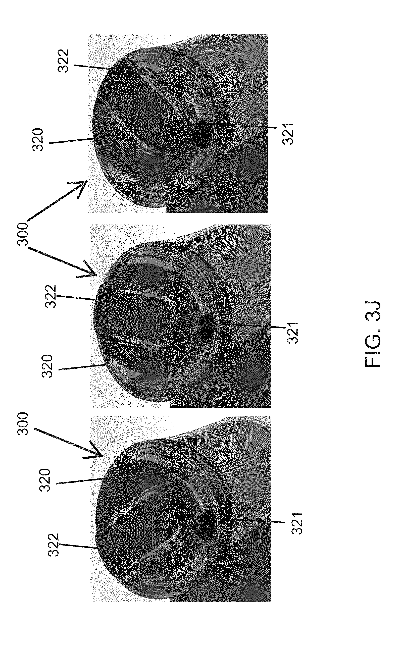
[0056] In various embodiments of the beverage container 300 shown in FIG. 3J, the lid 320 may provide the bar 322 and trigger 323 on the center, right side or left side of the lid for additional vision clearance. Different lids 320 having the different configurations can be provided and the user may determine which lid 320 to use. Arranging the bar 322 and trigger 323 to the left or right of the axis 301 may further improve the user's ability to see around the beverage container 300 during use.
[0057] FIGS. 4A-4F show a second embodiment of a beverage container 400 according to the present invention.
[0058] The beverage container 400 incorporates design and mechanical aspects that offer reduced vision loss during use while driving, an improved drinking angle for multi-task usage and a rubberized drinking valve that automatically seals upon releasing the trigger 423. A narrowed body with flattened back side offers optimal visibility of the road during use.
[0059] The overall shape of the outer perimeter of the beverage container 400 is non-circular, as shown for example in the top side and bottom side views of the beverage container 400 in FIG. 4B. In particular, the beverage container 400 has an oval shape defined by the lid 420 and at least a top portion of the outer wall 410, having a single axis of symmetry 401. A first section 402 of the perimeter of the lid 420, adjacent to the opening 421 of the beverage container 400, is curved and has a first radius of curvature. A second section 403 of the perimeter of the lid 420, opposite the opening 421 of the beverage container 400, is flattened and has a second radius of curvature that is greater than the first radius of curvature. The flattened, second section 403 is opposite the opening 421, such that during use of the beverage container 400, there is less obstruction in the user's line of vision. Although the cross-sectional shape at the top of the beverage container 400 defined by the lid 420 and top portion of the outer wall 410 are non-circular, the outer wall 410 may taper as it approaches the base of the beverage container 400 such that the base of the beverage container 400 may have a circular cross-section.
[0060] The beverage container 400 includes a lid 420 configured to be received in and attachable to a receptacle comprising an outer wall 410. The receptacle comprises an outer wall 410 and an inner wall 411. An insulating layer 412 is provided in between the outer wall 410 and inner wall 411 and the inner wall 411 surrounds a cavity 413 formed therein configured to receive a beverage. The insulating layer 412 may comprise a vacuum or may be filled with an insulating material, and is sealed by sealing or connecting the outer wall 410 and inner wall 411 at the top of the beverage container 400. The insulating layer 412 is configured to aid in maintaining the temperature of a hot or cold beverage in the cavity 413. The outer wall 410 may also comprise a grip 414 to assist a user in gripping the beverage container 400.
[0061] The lid 420 of the beverage container 400 comprises an opening 421 formed therethrough that allows any beverage in the cavity 413 to be dispensed from the beverage container 400. The lid 420 also comprises a valve that is configured to keep the opening 421 closed and provide a seal between the cavity 413 and opening 421 when the beverage container 400 is not in use or the user does not intend to dispense a beverage. The operation of the valve is shown for example in FIG. 4C. A lever 422 is provided on a top surface of the lid 420 and comprises a trigger 423 that extends over an edge of the lid 420. A valve is provided comprising a valve actuator 424 attached to a valve stem 425 and a valve dome 426 attached to the valve stem 425. The valve, and in particular the valve dome 426, are made from rubber or another flexible material. In an exemplary embodiment, the valve stem 425 extends through an opening in the lid 420 and the end of the lever 422 opposite the trigger 423 is attached to the valve stem 425. The lever 422 may comprise a slot or opening configured to receive the valve stem 425. The valve actuator 424 has a diameter greater than that of the slot or opening of the lever 422 and the valve stem 425.
[0062] At rest, the valve dome 426 is flexed upward, as shown for example in FIG. 4B and 4F. In this position, the valve dome 426 creates a gasket seal of the cavity 413 and keeps any beverage in the cavity 413 from passing around the valve dome 426 and out of the opening 421. When the trigger 423 is squeezed inward (i.e., towards the beverage container 400), it causes the lever 422 to lift the valve actuator 424, which causes the valve actuator 424 to lift the valve stem 425 and the center of the flexible valve dome 426. This causes the valve dome 426 to invert its shape, as shown in FIG. 4C, releasing the seal of the cavity 413 and allowing the beverage to pass through the opening 421. When the trigger 423 is released, the valve dome 426 returns to its original shape, resealing the cavity 413 of the beverage container 400.
[0063] The lid 420 has an oval shape and is configured to be secured to the receptacle of the beverage container 400 by inserting the lid 420 into the cavity 413 defined by the inner wall 411, which also has a corresponding oval shape at least at a top portion of the inner wall 411. In an exemplary embodiment of the beverage container 400, the lid 420 comprises one or more sealing gaskets arranged around a base section of the lid 420, which is configured to be inserted into the cavity 413 and secured to the inner wall 411 in a manner that seals any beverage in the cavity 413.
[0064] In the embodiment of the beverage container 400 shown in FIGS. 4A-4F, the beverage container may have various dimensions, including a height (D.sub.2) of approximately 187 millimeters and a greatest width (D.sub.3) of approximately 97.50 millimeters. However, the dimensions of the beverage container 400 may vary in alternative embodiments without departing from the scope of the invention.
[0065] The beverage container 400 provides several benefits. The dimensions of the beverage container promote full visibility during use. The double wall design offers standard look and feel externally, but has a slanted internal cavity which allows the liquid to pour at a less drastic angle, further opening the user's vision. The interior surfaces make liquid pour from a spout at a decreased angle without chugging or over pouring. Additionally, the rubberized mechanical valve has material memory. It is pulled inside out by trigger actuation and pulls back to original shape once released to achieve a full gasket seal.
[0066] FIGS. 5A-5G show a third embodiment of a beverage container 500 according to the present invention.
[0067] The overall shape of the outer perimeter of the beverage container 500 is non-circular, as shown for example in the top side and bottom side views of the beverage container 500 in FIG. 5D. In particular, the beverage container 500 has a shape of an oval or ellipse, defined by the lid 520 and at least a top portion of the outer wall 510. In the embodiment of the beverage container 500 shown in FIGS. 5A-5G, the beverage container 500, is elliptical, having two axes of symmetry 501a, 501b. The lid 520 has a first width (D.sub.8) extending through the opening 521 for dispensing the beverage that is less than a second width (D.sub.4) perpendicular to the first, defining the elliptical cross-sectional shape of the beverage container 500. During use of the beverage container 500, this non-circular, elliptical shape results in less obstruction in the user's line of vision. Although the cross-sectional shape at the top of the beverage container 500 defined by the lid 520 and top portion of the outer wall 510 are non-circular, the outer wall 510 may taper as it approaches the base of the beverage container 500 such that the base of the beverage container 500 may have a circular cross-section.
[0068] The beverage container 500 includes a lid 520 configured to be received in and attachable to a receptacle comprising an outer wall 510. The receptacle comprises an outer wall 510 and an inner wall 511. An insulating layer 512 is provided in between the outer wall 510 and inner wall 511 and the inner wall 511 surrounds a cavity 513 formed therein configured to receive a beverage. The insulating layer 512 may comprise a vacuum or may be filled with an insulating material, and is sealed by sealing or connecting the outer wall 510 and inner wall 511 at the top of the beverage container 500. The insulating layer 512 is configured to aid in maintaining the temperature of a hot or cold beverage in the cavity 513. The outer wall 510 may also comprise a grip 514 to assist a user in gripping the beverage container 500, which is configured to be secured to a grip recess 515 formed in the outer wall 510, shown for example in FIGS. 5F and 5G.
[0069] The lid 520 of the beverage container 500 comprises an opening 521 formed therethrough that allows any beverage in the cavity 513 to be dispensed from the beverage container 500. The lid 520 also comprises a slide 522 that is configured to keep the opening 521 closed and provide a seal between the cavity 513 and opening 521 when the beverage container 500 is not in use or the user does not intend to dispense a beverage. The lid 520 comprises a slide recess 524 that is configured to receive the slide 522 and permit the lateral movement of the slide 522 between a closed position and an opened position. In the closed position, the slide 522 covers the opening 521 through the lid 520 and the beverage cannot be dispensed from the cavity 513. The slide 522 can be moved laterally away from the opening 521 to an opened position, in which the beverage can be dispensed through the opening 521. The slide 522 may comprise an air vent hole 523 and the slide recess 524 may also comprise an air vent hole 525. In the closed position, the two air vent holes 523, 525 are configured to be in alignment and allow air to pass into or out of the cavity 513. The slide 522 may comprise a projection that is configured to aid the user in sliding the slide 522 laterally between the opened and closed positions.
[0070] The lid 520 has an elliptical or oval shape and is configured to be secured to the receptacle of the beverage container 500 by inserting the lid 520 into the cavity 513 defined by the inner wall 511, which also has a corresponding elliptical or oval shape at least at a top portion of the inner wall 511. In an exemplary embodiment of the beverage container 500, the lid 520 comprises one or more sealing gaskets 526b arranged around a base section 526a of the lid 520, which is configured to be inserted into the cavity 513 and secured to the inner wall 511 in a manner that seals any beverage in the cavity 513.
[0071] In the embodiment of the beverage container 500 shown in FIGS. 5A-5G, the beverage container may have various dimensions, shown for example in FIG. 5D, including a height (D.sub.6) of approximately 207 millimeters, a first width (D.sub.8) of approximately 68 millimeters, a second width (D.sub.4) of approximately 90 millimeters, a base diameter (D.sub.5) of approximately 68 millimeters, a lid height (D.sub.7) of approximately 38.5 millimeters, a wall thickness (D.sub.9) of approximately 1.8 millimeters and a grip height (D.sub.10) of approximately 75 millimeters. However, the dimensions of the beverage container 500 may vary in alternative embodiments without departing from the scope of the invention.
[0072] FIGS. 6A-6D show a fourth embodiment of a beverage container according to the present invention.
[0073] The overall shape of the outer perimeter of the beverage container 600 is non-circular, as shown for example in the top side and bottom side views of the beverage container 600 in FIG. 6C. In particular, the beverage container 600 has a shape of an oval or ellipse, defined by the lid 620 and at least a top portion the outer wall 610. In the embodiment of the beverage container 600 shown in FIGS. 6A-6D, the beverage container 600, is elliptical, having two axes of symmetry 601a, 601b. The lid 620 has a first width (D.sub.14) extending through the opening 621 for dispensing the beverage that is less than a second width (D.sub.11) perpendicular to the first, defining the elliptical cross-sectional shape of the beverage container 600. During use of the beverage container 600, this elliptical shape results in less obstruction in the user's line of vision. Although the cross-sectional shape at the top of the beverage container 600 defined by the lid 620 and top portion of the outer wall 610 are non-circular, the outer wall 610 may taper as it approaches the base of the beverage container 600 such that the base of the beverage container 600 may have a circular cross-section.
[0074] The beverage container 600 includes a lid 620 configured to be received in and attachable to a receptacle comprising an outer wall 610. The receptacle comprises an outer wall 610 and an inner wall 611. An insulating layer 612 is provided in between the outer wall 610 and inner wall 611 and the inner wall 611 surrounds a cavity 613 formed therein configured to receive a beverage. The insulating layer 612 may comprise a vacuum or may be filled with an insulating material, and is sealed by sealing or connecting the outer wall 610 and inner wall 611 at the top of the beverage container 600. The insulating layer 612 is configured to aid in maintaining the temperature of a hot or cold beverage in the cavity 613. The outer wall 610 may also comprise a grip 614 to assist a user in gripping the beverage container 600.
[0075] The lid 620 of the beverage container 600 comprises an opening 621 formed therethrough that allows any beverage in the cavity 613 to be dispensed from the beverage container 600. The lid 620 also comprises a valve that is configured to keep the opening 621 closed and provide a seal between the cavity 613 and opening 621 when the beverage container 600 is not in use or the user does not intend to dispense a beverage. The operation of the valve is shown for example in FIG. 6D. A lever 622 is provided on a top surface of the lid 620 and comprises a trigger 623 that extends over an edge of the lid 620. A valve is provided comprising a valve actuator 624 attached to a valve stem 625 and a valve dome 626 attached to the valve stem 625. The valve, and in particular the valve dome 626, are made from rubber or another flexible material. In an exemplary embodiment, the valve stem 625 extends through an opening in the lid 620 and the end of the lever 622 opposite the trigger 623 is attached to the valve stem 625. The lever 622 may comprise a slot or opening 628 configured to receive the valve stem 625. The valve actuator 624 has a diameter greater than that of the slot 628 of the lever 622 and the valve stem 625. The lid 620 may also comprise a recess 627a configured to receive the lever 622. The recess 627a may include a vent hole 627b to allow air to pass into and out of the cavity 613 when the beverage container 610 is opened.
[0076] At rest, the valve dome 626 is flexed upward, as shown for example in FIGS. 6C and left side of FIG. 6D. In this position, the valve dome 626 creates a gasket seal of the cavity 613 and keeps any beverage in the cavity 613 from passing around the valve dome 626 and out of the opening 621. When the trigger 623 is squeezed inward (as shown in the right side of FIG. 6D), it causes the lever 622 to lift the valve actuator 624, which causes the valve actuator 624 to lift the valve stem 625 and the center of the flexible valve dome 626. This causes the valve dome 626 to invert its shape, releasing the seal of the cavity 613 and allowing the beverage to pass through the opening 621. When the trigger 623 is released, the valve dome 626 returns to its original shape, resealing the cavity 613 of the beverage container 600.
[0077] The lid 620 has an elliptical shape and is configured to be secured to the receptacle of the beverage container 600 by inserting the lid 620 into the cavity 613 defined by the inner wall 611, which also has a corresponding elliptical shape at least at a top portion of the inner wall 611. In an exemplary embodiment of the beverage container 600, the lid 620 comprises one or more sealing gaskets 629b arranged around a base section 629a of the lid 620, which is configured to be inserted into the cavity 613 and secured to the inner wall 611 in a manner that seals any beverage in the cavity 613.
[0078] In the embodiment of the beverage container 600 shown in FIGS. 6A-6D, the beverage container may have various dimensions, as shown for example in FIG. 6C, including a height (D.sub.13) of approximately 8 inches, a first width (D.sub.14) of approximately 2.68 inches, a second width (D.sub.11) of approximately 3.54 inches, and a base diameter (D.sub.12) of approximately 2.68 inches. However, the dimensions of the beverage container 600 may vary in alternative embodiments without departing from the scope of the invention.
[0079] In various alternative embodiments of the invention, various features of the beverage containers 300, 400, 500, 600 may be substituted and/or used in alternative combinations without departing from the scope of the invention.
[0080] The travel beverage container of the present invention may also be provided in a disposable form, as shown for example in FIGS. 7A-9D. A challenge facing the design of a disposable container having an oval or elliptical shape is that without the gaskets and firm plastic to hold the form of the vessel, a paper cup, or a cup made from another disposable material, has a propensity to collapse when squeezed too firmly. To address this problem, a series of concentric ribs are molded directly into the underside of the lid to provide resistance if the cup begins to bend, and maintain a watertight seal. The disposable beverage containers can be made from materials that are known in the art and used in disposable cups or containers, including for example, paper and other synthetic materials.
[0081] FIGS. 7A-7D show a first embodiment of a disposable beverage container according to the present invention.
[0082] The overall shape of the outer perimeter of the beverage container 700 is non-circular, as shown for example in the top side and bottom side views of the beverage container 700 in FIG. 7D. In particular, the beverage container 700 has a shape of an oval or ellipse, defined by the lid 720 and at least a top portion of the container wall 710. In the embodiment of the beverage container 700 shown in FIGS. 7A-7D, the beverage container 700, is elliptical, having two axes of symmetry 701a, 701b. The lid 720 has a first width extending through the opening 721 for dispensing the beverage that is less than a second width perpendicular to the first width, defining the elliptical cross-sectional shape of the beverage container 700. During use of the beverage container 700, this non-circular, elliptical shape results in less obstruction in the user's line of vision. Although the cross-sectional shape at the top of the beverage container 700 defined by the lid 720 and top portion of the container wall 710 are non-circular, the container wall 710 may taper as it approaches the base of the beverage container 700 such that the base of the beverage container 700 may have a circular cross-section.
[0083] The beverage container 700 includes a lid 720 configured to be attachable to a container wall 710. The container wall 710 surrounds a cavity formed therein configured to receive a beverage.
[0084] The lid 720 of the beverage container 700 comprises an opening 721 formed therethrough that allows any beverage in the cavity to be dispensed from the beverage container 700. The lid 720 has an elliptical or oval shape and is configured to be secured to the container wall 710, which also has a corresponding elliptical or oval shape at least at a top portion of the container wall 710. In an exemplary embodiment of the beverage container 700, the lid 720 comprises a lip 724 that is configured to receive a lip 711 around the top of the container wall 710 to secure the lid 720 to the container wall 710. In the beverage container 700, the lid 720 is formed with a raised surface extending above the lip 724. The lid 720 also comprises a plurality of ribs 723 molded directly into the lid 720. The ribs 723 of the lid 720 are configured to provide resistance if the beverage container 700 or lid 720 begin to bend, in order to keep the lid 720 secured to the container wall 710 and maintain a watertight seal.
[0085] In the embodiment of the beverage container 700 shown in FIGS. 7A-7D, the beverage container may have various dimensions, shown for example in FIG. 7D, including a container wall height (D.sub.15) of approximately 118 millimeters, a lid height (D.sub.17) of approximately 26 millimeters, and a total height (D.sub.16) of approximately 133 millimeters. However, the dimensions of the beverage container 700 may vary in alternative embodiments without departing from the scope of the invention.
[0086] FIGS. 8A-8B show a second embodiment of a disposable beverage container according to the present invention.
[0087] The overall shape of the outer perimeter of the beverage container 800 is non-circular, as shown for example in the top side and bottom side views of the beverage container 800 in FIG. 8B. In particular, the beverage container 800 has a shape of an oval or ellipse, defined by the lid 820 and at least a top portion of the container wall 810. In the embodiment of the beverage container 800 shown in FIGS. 8A-8B, the beverage container 800 is elliptical, having two axes of symmetry 801a, 801b. The lid 820 has a first width (D.sub.21) extending through the opening 821 for dispensing the beverage that is less than a second width (D.sub.ig) perpendicular to the first width, defining the elliptical cross-sectional shape of the beverage container 800. During use of the beverage container 800, this non-circular, elliptical shape results in less obstruction in the user's line of vision. Although the cross-sectional shape at the top of the beverage container 800 defined by the lid 820 and top portion of the container wall 810 are non-circular, the container wall 810 may taper as it approaches the base of the beverage container 800 such that the base of the beverage container 800 may have a circular cross-section.
[0088] The beverage container 800 includes a lid 820 configured to be attachable to a container wall 810. The container wall 810 surrounds a cavity formed therein configured to receive a beverage.
[0089] The lid 820 of the beverage container 800 comprises an opening 821 formed therethrough that allows any beverage in the cavity to be dispensed from the beverage container 800. The lid 820 may further comprise a cover 822 including a tab, which is configured to cover the opening 821, and which can be raised to uncover the opening 821. The lid 820 has an elliptical or oval shape and is configured to be secured to the container wall 810, which also has a corresponding elliptical or oval shape at least at a top portion of the container wall 810. In an exemplary embodiment of the beverage container 800, the lid 820 comprises a lip 824 that is configured to receive a lip around the top of the container wall 810 to secure the lid 820 to the container wall 810. The lid 820 also comprises a plurality of ribs or pillars 823 molded directly into the lid 820 and extending beneath a top surface of the lid 820. The ribs 823 of the lid 820 are configured to provide structural rigidity and resistance if the beverage container 800 or lid 820 begins to bend, in order to keep the lid 820 secured to the container wall 810 and maintain a watertight seal.
[0090] In the embodiment of the beverage container 800 shown in FIGS. 8A-8B, the beverage container 800 may have various dimensions, shown for example in FIG. 8B, including a total height (D.sub.18) of approximately 4.64 inches, a first width (D.sub.21) of approximately 2.89 inches, a second width (D.sub.19) of approximately 3.77 inches and a base width (D.sub.20) of approximately 2.24 inches. However, the dimensions of the beverage container 800 may vary in alternative embodiments without departing from the scope of the invention.
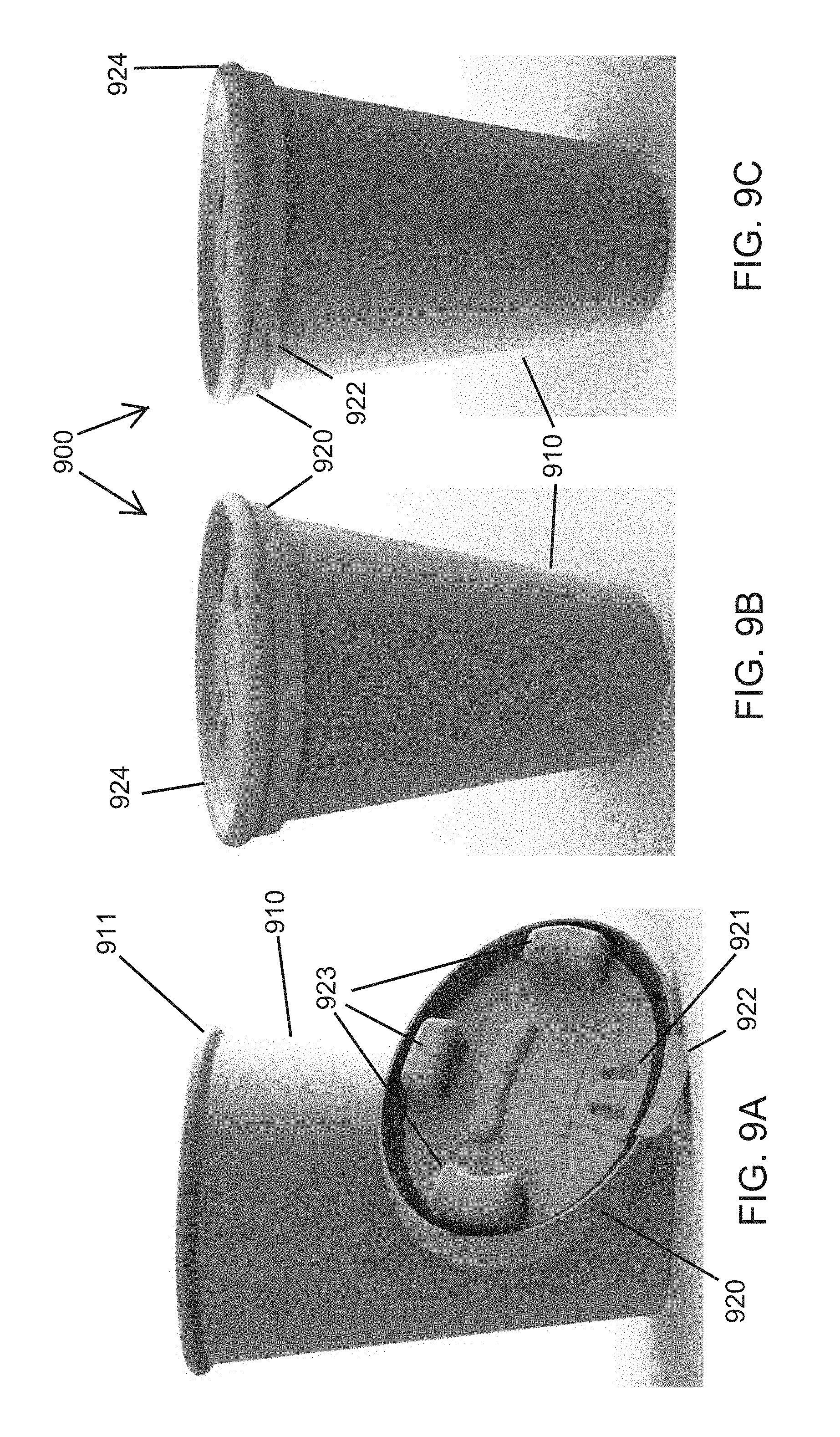
[0091] FIGS. 9A-9D show a third embodiment of a disposable beverage container according to the present invention.
[0092] The overall shape of the outer perimeter of the beverage container 900 is non-circular, as shown for example in the top side and bottom side views of the beverage container 900 in FIG. 9D. In particular, the beverage container 900 has a shape of an oval or ellipse, defined by the lid 920 and at least the top portion the container wall 910. In the embodiment of the beverage container 900 shown in FIGS. 9A-9B, the beverage container 900 is elliptical, having two axes of symmetry 901a, 901b. The lid 920 has a first width (D.sub.21) extending through the opening 921 for dispensing the beverage that is less than a second width (D.sub.19) perpendicular to the first width, defining the elliptical cross-sectional shape of the beverage container 900. During use of the beverage container 900, this non-circular, elliptical shape results in less obstruction in the user's line of vision. Although the cross-sectional shape at the top of the beverage container 900 defined by the lid 920 and top portion of the container wall 910 are non-circular, the container wall 910 may taper as it approaches the base of the beverage container 900 such that the base of the beverage container 900 may have a circular cross-section.
[0093] The beverage container 900 includes a lid 920 configured to be attachable to a container wall 910. The container wall 910 surrounds a cavity formed therein configured to receive a beverage.
[0094] The lid 920 of the beverage container 900 comprises an opening 921 formed therethrough that allows any beverage in the cavity to be dispensed from the beverage container 900. The lid 920 may further comprise a cover 922 including a tab, which is configured to cover the opening 921, and which can be raised to uncover the opening 921. The lid 920 has an elliptical or oval shape and is configured to be secured to the container wall 910, which also has a corresponding elliptical or oval shape at least at a top portion of the container wall 910. In an exemplary embodiment of the beverage container 900, the lid 920 comprises a lip 924 that is configured to receive a lip 911 around the top of the container wall 910 to secure the lid 920 to the container wall 910. The lid 920 also comprises a plurality of ribs or pillars 923 molded directly into the lid 920 and extending beneath a top surface of the lid 920. The ribs 923 of the lid 920 are configured to provide structural rigidity and resistance if the beverage container 900 or lid 920 begins to bend, in order to keep the lid 920 secured to the container wall 910 and maintain a watertight seal.
[0095] In the embodiment of the beverage container 900 shown in FIGS. 9A-9D, the beverage container 900 may have various dimensions, shown for example in FIG. 9D, including a total height (D.sub.23) of approximately 4.61 inches, a first width (D.sub.26) of approximately 2.56 inches, a second width (D.sub.24) of approximately 3.54 inches and a base width (D.sub.22, D.sub.25) of approximately 2.3 inches. However, the dimensions of the beverage container 900 may vary in alternative embodiments without departing from the scope of the invention.
[0096] Other attempts to create an oval or elliptical disposable cup have failed due to leaking. The unique pillar or rib system of the disposable beverage containers 700, 800, 900 creates even pressure around the lid making a leak proof seal. The oval or elliptical shape of the beverage container 700, 800, 900 offers superior visibility when consuming a beverage while driving.
[0097] It should be understood that, unless stated otherwise herein, any of the features, characteristics, alternatives or modifications described regarding a particular embodiment herein may also be applied, used, or incorporated with any other embodiment described herein. Additionally, the drawings herein may not be drawn to scale in whole or in part.
[0098] Although the invention has been described and illustrated with respect to exemplary embodiments thereof, the foregoing and various other additions and omissions may be made therein and thereto without departing from the spirit and scope of the present invention.
* * * * *
D00000
D00001
D00002
D00003
D00004
D00005
D00006
D00007
D00008
D00009
D00010
D00011
D00012

D00013
D00014
D00015

D00016

D00017

D00018

D00019
D00020
XML
uspto.report is an independent third-party trademark research tool that is not affiliated, endorsed, or sponsored by the United States Patent and Trademark Office (USPTO) or any other governmental organization. The information provided by uspto.report is based on publicly available data at the time of writing and is intended for informational purposes only.
While we strive to provide accurate and up-to-date information, we do not guarantee the accuracy, completeness, reliability, or suitability of the information displayed on this site. The use of this site is at your own risk. Any reliance you place on such information is therefore strictly at your own risk.
All official trademark data, including owner information, should be verified by visiting the official USPTO website at www.uspto.gov. This site is not intended to replace professional legal advice and should not be used as a substitute for consulting with a legal professional who is knowledgeable about trademark law.