Cosmetic Material Container
KAMITANI; Kazuyuki
U.S. patent application number 16/075865 was filed with the patent office on 2019-02-21 for cosmetic material container. The applicant listed for this patent is SHISEIDO COMPANY, LTD.. Invention is credited to Kazuyuki KAMITANI.
| Application Number | 20190053603 16/075865 |
| Document ID | / |
| Family ID | 59563044 |
| Filed Date | 2019-02-21 |


| United States Patent Application | 20190053603 |
| Kind Code | A1 |
| KAMITANI; Kazuyuki | February 21, 2019 |
COSMETIC MATERIAL CONTAINER
Abstract
A cosmetic material container constituted by a main body and a lid member is configured such that one of a pair of abutment surfaces that abut each other when fitted is a cam surface and the other is a follower surface. The cam surface and the follower surface are configured to relatively move the main body and the lid member in a direction of a rotational axis in response to rotation of the lid member with respect to the main body. The main body and the lid member move between a fitted position at which the abutment surfaces abut each other and are held together by magnetic force, and a separated position at which the abutment surfaces are separated from each other against the magnetic force, by rotation of the lid member with respect to the main body.
| Inventors: | KAMITANI; Kazuyuki; (Kanagawa, JP) | ||||||||||
| Applicant: |
|
||||||||||
|---|---|---|---|---|---|---|---|---|---|---|---|
| Family ID: | 59563044 | ||||||||||
| Appl. No.: | 16/075865 | ||||||||||
| Filed: | February 10, 2017 | ||||||||||
| PCT Filed: | February 10, 2017 | ||||||||||
| PCT NO: | PCT/JP2017/004890 | ||||||||||
| 371 Date: | August 6, 2018 |
| Current U.S. Class: | 1/1 |
| Current CPC Class: | A45D 2040/0025 20130101; A45D 40/06 20130101; A45D 34/00 20130101; B65D 5/00 20130101; B65D 2313/04 20130101; A45D 40/00 20130101; A45D 40/02 20130101; A45D 2200/055 20130101 |
| International Class: | A45D 40/06 20060101 A45D040/06; A45D 34/00 20060101 A45D034/00 |
Foreign Application Data
| Date | Code | Application Number |
|---|---|---|
| Feb 12, 2016 | JP | 2016-025322 |
Claims
1. A cosmetic material container, comprising: a main body that houses a cosmetic material; a lid member which is fitted onto the main body in a relatively rotatable manner; and at least one set of magnets that maintain a fitted state between the main body and the lid member; the main body and the lid member respectively having abutment surfaces that abut each other during a fitting operation; the abutment surfaces being configured to separate and approach each other between a position at which the main body and the lid member are positioned at a predetermined position in a rotational direction of the lid member such that the abutment surfaces abut each other, and a position other than the predetermined position at which the main body and the lid member are separated in a direction of a rotational axis; the lid member being movable between a fitted position at which the abutment surfaces abut each other and the main body and the lid member are maintained in a fitted state by magnetic force, and a separated position at which the abutment surfaces are in the position other than the predetermined position, separated from each other against the magnetic force, by rotating the lid member.
2. A cosmetic material container, comprising: a main body that houses a cosmetic material; a lid member which is fitted onto the main body in a relatively rotatable manner; and at least one set of magnets that maintain a fitted state between the main body and the lid member; the main body and the lid member respectively having abutment surfaces that abut each other during a fitting operation; one of the abutment surfaces including a cam surface, and the other of the abutment surfaces including a follower surface that follows along the cam surface; the cam surface and the follower surface being configured to move the main body and the lid member in a direction of a rotational axis in response to relative rotation of the lid member with respect to the main body; and the lid member being movable between a fitted position at which the abutment surfaces abut each other and the main body and the lid member are maintained in a fitted state by magnetic force, and a separated position at which the abutment surfaces are separated from each other against the magnetic force, by rotating the lid member.
3. A cosmetic material container as defined in claim 2, wherein: one of the cam surface and the follower surface is formed as a recessed portion provided in one of the abutment surfaces, and the other of the cam surface and the follower surface is formed on the other of the abutment surfaces as a protruding portion that abuts the recessed portion; and the main body and the lid member are configured to separate by the recessed portion riding up on the protruding portion due to the rotation.
4. A cosmetic material container as defined in claim 3, wherein: a plurality of combinations of the recessed portion and the protruding portion are provided along an arc having the rotational axis as its center.
5. A cosmetic material container as defined in claim 1, wherein: the main body is a cylinder; and a lipstick which is capable of being fed out is contained in the cylinder.
6. A cosmetic material container as defined in claim 1, wherein: an outer peripheral surface of the lid member and an outer peripheral surface of the main body are coplanar in the fitted state.
7. A cosmetic material container as defined in claim 1, wherein: the cross sectional shapes of the main body and the lid member perpendicular to the direction of the rotational axis are linearly symmetrical with respect to one line.
8. A cosmetic material container as defined in claim 1, further comprising: a plurality of the sets of magnets.
9. A cosmetic material container as defined in claim 1, wherein: one of the sets of magnets is provided at one of the abutment surfaces, and the other of the sets of magnets is provided at the other of the abutment surfaces.
10. A cosmetic material container as defined in claim 9, wherein: the one of the sets of magnets at one of the abutment surfaces has an N pole facing the other abutment surface, and the other of the sets of magnets at the other of the abutment surfaces has an S pole facing the one of the abutment surfaces.
11. A cosmetic material container as defined in claim 1, wherein: magnetic force that leaks from the set of magnets in the fitted state is being 500 gauss or less.
12. A cosmetic material container, comprising: a main body that houses a cosmetic material; a lid member which is fitted onto the main body; and at least one set of magnets that maintain a fitted state between the main body and the lid member; the main body and the lid member respectively having abutment surfaces that abut each other during a fitting operation; and one of the abutment surfaces including a cam surface, and the other of the abutment surfaces including a follower surface that follows along the cam surface.
13. A cosmetic material container as defined in claim 2, wherein: the main body is a cylinder; and a lipstick which is capable of being fed out is contained in the cylinder.
14. A cosmetic material container as defined in claim 2, wherein: an outer peripheral surface of the lid member and an outer peripheral surface of the main body are coplanar in the fitted state.
15. A cosmetic material container as defined in claim 2, wherein: the cross sectional shapes of the main body and the lid member perpendicular to the direction of the rotational axis are linearly symmetrical with respect to one line.
16. A cosmetic material container as defined in claim 2, further comprising: a plurality of the sets of magnets.
17. A cosmetic material container as defined in claim 2, wherein: one of the sets of magnets is provided at one of the abutment surfaces, and the other of the sets of magnets is provided at the other of the abutment surfaces.
18. A cosmetic material container as defined in claim 17, wherein: the one of the sets of magnets at one of the abutment surfaces has an N pole facing the other abutment surface, and the other of the sets of magnets at the other of the abutment surfaces has an S pole facing the one of the abutment surfaces.
19. A cosmetic material container as defined in claim 2, wherein: magnetic force that leaks from the set of magnets in the fitted state is 500 gauss or less.
Description
CROSS REFERENCE TO RELATED APPLICATIONS
[0001] The present application is a National Phase Entry of PCT International Application No. PCT/JP2017/004890 filed on Feb. 10, 2017, which claims priority under 35 U.S.C. .sctn. 119(a) to Japanese Patent Application No. 2016-025322 filed on Feb. 12, 2016. Each of the above applications is hereby expressly incorporated by reference, in its entirety, into the present application.
TECHNICAL FIELD
[0002] The present disclosure is related to a cosmetic material container. More specifically, the present disclosure is related to a cosmetic material container equipped with a main body that houses a cosmetic material such as lipstick, a lid member that fits on the main body in a rotatable manner, and a magnet that maintains the main body and the lid member in a fitted state by magnetic force.
BACKGROUND ART
[0003] In conventional cosmetic material containers constituted by a main body that houses a cosmetic material and a lid member that fits on the main body in a rotatable manner, a technique that mounts magnets on each of a main body and a lid member in order to maintain a fitted state is well known (Japanese Unexamined Utility Model Publication No. S57-187117).
[0004] In cosmetic material containers provided with fit maintaining magnets, a technique that provides markings on the outer peripheral surfaces of a main body and a lid member in order to prevent the same magnetic poles facing each other by positioning opposite magnetic poles to face each other during fitting is also a known technique (Japanese Patent No. 5480553). Further, there is also a known technique that provides a stepped portion on a main body and a recessed portion that engages with the stepped portion on a lid member to perform more accurate positioning, because positioning that only utilizes magnetic force may generate a degree of positioning shift.
SUMMARY
[0005] It is necessary to employ magnets having strong magnetic force if positioning is performed utilizing only magnetic force, as in Japanese Unexamined Utility Model Publication No. S57-187117 and Japanese Patent No. 5480553. Therefore, a strong pulling force will be necessary when removing the lid member from the main body, and there is a problem that removal will be difficult.
[0006] In addition, there are many cases in which cosmetic material containers are carried in bags or the like. If the magnetic force that leaks from the cosmetic material container is strong, there is a possibility that various electronic devices and various magnetic strip card which are in the same bag will be influenced by the magnetic force. However, the above patent documents neither disclose nor suggest suppressing magnetic force from leaking from the cosmetic material containers, or to facilitate removal of the lid members form the main bodies.
[0007] The present disclosure has been developed in view of the foregoing circumstances. The present disclosure provides a cosmetic material container that maintains a fitted state between a main body and a lid member by magnetic force, that suppresses the leakage of magnetic force, facilitates removal of the lid member from the main body, and facilitates positive positioning of the main body and the lid member at a predetermined position in a rotational direction of the lid member, without sacrificing the pleasant sensation of magnetic attraction by the magnetic force during fitting operations.
Means for Solving the Problem
[0008] A cosmetic material container of the present disclosure that achieves the above objective comprises:
[0009] a main body that houses a cosmetic material;
[0010] a lid member which is fitted onto the main body in a relatively rotatable manner; and
[0011] at least one set of magnets that maintain a fitted state between the main body and the lid member;
[0012] the main body and the lid member respectively having abutment surfaces that abut each other during a fitting operation;
[0013] the abutment surfaces being configured to separate and approach each other between a position at which the main body and the lid member are positioned at a predetermined position in a rotational direction of the lid member such that the abutment surfaces abut each other, and a position other than the predetermined position at which the main body and the lid member are separated in a direction of a rotational axis;
[0014] the lid member being movable between a fitted position at which the abutment surfaces abut each other and the main body and the lid member are maintained in a fitted state by magnetic force, and a separated position at which the abutment surfaces are in the position other than the predetermined position, separated from each other against the magnetic force, by rotating the lid member.
[0015] Here, the "lid member which is fitted onto the main body in a relatively rotatable manner" means that one of the lid member and the main body is rotatable with respect to the other in a state in which the main body and the lid member are fitted. This configuration is not limited to that in which one is fixed and the other is rotated, and a configuration in which both the main body and the lid member rotate is also possible.
[0016] The abutment surfaces are configured to separate and approach each other between a position at which the main body and the lid member are positioned at the predetermined position in the rotational direction of the lid member such that the abutment surfaces abut each other, and the position other than the predetermined position at which the main body and the lid member are separated in the direction of the rotational axis thereof by relative rotation of the main body and the lid member. The main body and the lid member may be configured such that a recessed portion is formed on one of the abutment surfaces and a protruding portion that abuts the recessed portion is formed the other of the abutment surfaces, and separate from each other by the recessed portion riding up on the protruding portion due to the relative rotation. Here, "separate" means that the main body and the lid member move away from each other, and "separate and approach" means that the main body and the lid member move away from and abut each other.
[0017] That is, the main body and the lid member are in a relationship in which the protruding portion formed on the abutment surface of one of the two moves in a sliding direction along the recessed portion, which is formed on the abutment surface on the abutment surface of the other, along an arc having the rotational axis as the center, by the lid member being rotated with respect to the main body. Thereby, the lid member can be separated from the main body, by rotating the lid member with respect to the main body.
[0018] In addition, in the cosmetic material container of the present disclosure, a plurality of combinations of the recessed portion and the protruding portion may be provided along the arc having the rotational axis as the center.
[0019] In addition, in the cosmetic material container of the present disclosure, the main body may be a cylinder, and a cosmetic material which is capable of being fed out, lipstick, for example, may be housed in the cylinder.
[0020] In addition, in the cosmetic material container of the present disclosure, the outer peripheral surface of the lid member and the outer peripheral surface of a base end portion of the main body may be coplanar in the fitted state.
[0021] In addition, in the cosmetic material container of the present disclosure, the cross sectional shape of the main body and the lid member in a direction perpendicular to the rotational axis may be linearly symmetrical with respect to one line.
[0022] In addition, the cosmetic material container of the present disclosure may be equipped with a plurality of sets of magnets.
[0023] Here, a "set of magnets" refers to a combination of an S pole of one magnet provided at the abutment surface of the main body, and an N pole of another magnet provided at the abutment surface of the lid member.
[0024] In addition, in the cosmetic material container of the present disclosure, it is desirable for one of the set of magnets at a first one of the corresponding abutment surfaces to have an N pole facing a second abutment surface and for the other of the set of magnets at the second abutment surface to have an S pole facing the corresponding first abutment surface. That is, it is desirable for magnetic poles of the same polarity to be exposed on the same abutment surface.
[0025] In addition, in the cosmetic material container of the present disclosure, it is desirable for the magnetic force that leaks from the set of magnets in the fitted state to be 500 gauss or less.
Advantageous Effects of the Disclosure
[0026] According to the cosmetic material container of the present disclosure, the cosmetic material container maintains the fitted state between the main body and the lid member by magnetic force. The abutment surfaces of the main body and the lid member that abut each other during a fitting operation are configured to separate and approach each other between the position at which the main body and the lid member are positioned at the predetermined position in a rotational direction of the lid member such that the abutment surfaces abut each other, and the position other than the predetermined position at which the main body and the lid member are separated in a direction of the rotational axis. The lid member is movable between a fitted position at which the abutment surfaces abut each other and the main body and the lid member are maintained in a fitted state by magnetic force, and a separated position at which the abutment surfaces are in the position other than the predetermined position, separated from each other against the magnetic force, by rotating the lid member. Therefore, positioning is not performed only by magnetic force, and it is not necessary for the magnetic force of the magnets to be great. As a result, removal of the lid member from the main body is facilitated, and accurate positioning of the main body and the lid member at the predetermined position in the rotational direction is also facilitated.
[0027] A user will experience a sensation that positioning and fitting are automatically performed without sacrificing the pleasant sensation of magnetic attraction by the magnetic force during fitting operations, because if the main body is held and the lid member is rotated, the lid member will be fitted at the predetermined position by magnetic attraction of the magnetic force when the lid member is at a position close to the predetermined position.
BRIEF DESCRIPTION OF THE DRAWINGS
[0028] FIG. 1 is a perspective view that illustrates a cosmetic material container in a state in which a lid member is fitted onto a main body.
[0029] FIG. 2 is a perspective view that illustrates the cosmetic material container in a state in which the lid member is removed from the main body.
[0030] FIG. 3 is a plan view of the main body of the cosmetic material container.
[0031] FIG. 4 is a bottom view of the lid member of the cosmetic material container.
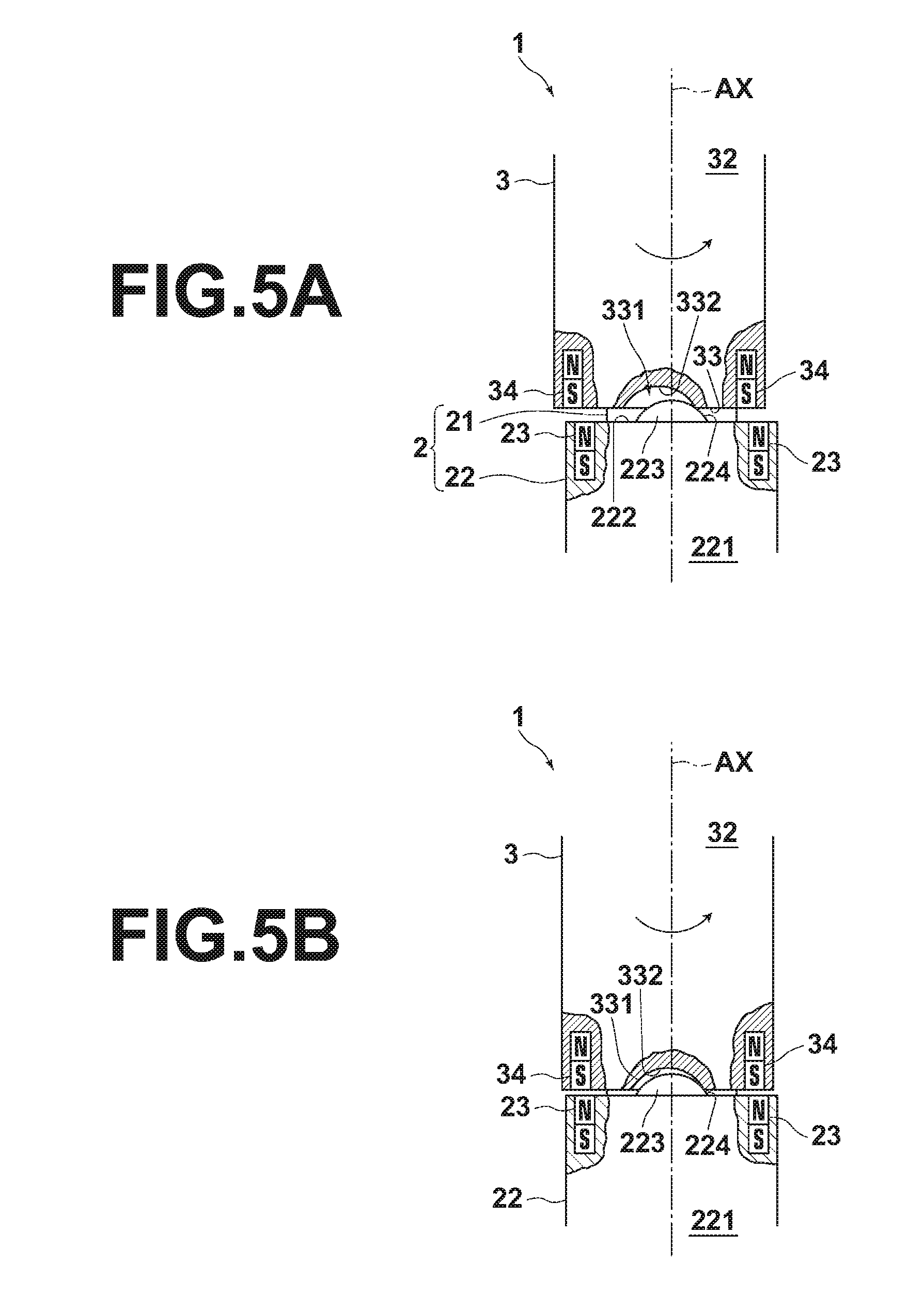
[0032] FIG. 5A is a first schematic diagram that illustrates transitions between the state in which the lid member is fitted on the main body and the state in which the lid member is removed from the main body.
[0033] FIG. 5B is a second schematic diagram that illustrates transitions between the state in which the lid member is fitted on the main body and the state in which the lid member is removed from the main body.
[0034] FIG. 5C is a third schematic diagram that illustrates transitions between the state in which the lid member is fitted on the main body and the state in which the lid member is removed from the main body.
[0035] FIG. 5D is a fourth schematic diagram that illustrates transitions between the state in which the lid member is fitted on the main body and the state in which the lid member is removed from the main body.
[0036] FIG. 6 is a schematic diagram that illustrates a first modification of a combination of a protruding portion and a recessed portion of the cosmetic material container.
[0037] FIG. 7 is a schematic diagram that illustrates a second modification of the combination of the protruding portion and the recessed portion of the cosmetic material container.
[0038] FIG. 8 is a schematic diagram that illustrates a third modification of the combination of the protruding portion and the recessed portion of the cosmetic material container.
[0039] FIG. 9 is a schematic diagram that illustrates a fourth modification of the combination of the protruding portion and the recessed portion of the cosmetic material container.
[0040] FIG. 10 is a schematic diagram that illustrates a fifth modification of the combination of the protruding portion and the recessed portion of the cosmetic material container.
[0041] FIG. 11 is a diagram that illustrates a cosmetic material container according to a second embodiment.
[0042] FIG. 12 is a diagram that illustrates the results of comparison between the cosmetic material container of the present disclosure and another cosmetic material container.
[0043] FIG. 13 is a perspective view that illustrates a cosmetic material container according to a third embodiment of the present disclosure.
DETAILED DESCRIPTION OF THE EMBODIMENTS
[0044] Hereinafter, a cosmetic material container 1 according to an embodiment of the present disclosure will be described in detail with reference to the attached drawings.
[0045] The cosmetic material container 1 houses a cosmetic material for lips (including lipstick, lip color, lip liner, lip cream, lip gloss, and lip essence) in the form of a stick. Note that the cosmetic material container of the present disclosure is not limited to housing a cosmetic material for lips, and may be applied to any cosmetic material container that houses any cosmetic material, as long as the cosmetic material container is that of an aspect having a main body and a lid member having a fitting portion which is rotatable. For example, the cosmetic material container of the present disclosure may be applied to cosmetic material containers of the dispenser type and the pump type.
[0046] As illustrated in FIG. 1 through FIG. 4, the cosmetic material container 1 is constituted mainly by a main body 2, and a lid member 3 which is fitted on the main body 2 in a manner rotatable about a rotational axis AX. FIG. 1 illustrates a state in which the lid member 3 is fitted on the main body 2, and FIG. 2 illustrates a state in which the lid member 3 and the main body 2 are separated. In addition, FIG. 3 is a plan view of the main body 2, and FIG. 4 is a bottom view of the lid member 3.
[0047] As illustrated in FIG. 2, the main body 2 is mainly constituted by a columnar portion 21 that houses lipstick, which is not illustrated, and a base end portion 22 having a greater outer dimension than the outer diameter of the columnar portion 21. The columnar portion 21 is a cylinder having an opening 211 at the upper end thereof. The lipstick is inserted into the columnar portion 21 through the opening 211, and is contained therein.
[0048] In the cosmetic material container 1, the base end portion 22 is relatively rotatable with respect to the columnar portion 21. The cosmetic material container 1 is equipped with a known feeding mechanism that enables the lipstick, which is not illustrated, to be fed out from the opening 211 by rotating the base end portion 22 while holding the columnar portion 21.
[0049] As illustrated in FIG. 2, the lid member 3 is a bottomed cylinder. A penetrating aperture 31 for the columnar portion 21 to penetrate through is formed in the lower end of the lid member 3 (the lid member is illustrated inverted in the vertical direction in FIG. 2). The shapes of the outer peripheral surfaces of the base end portion 22 of the main body 2 and the lid member 3 are substantially the same, particularly at a fitting portion, and in the fitted state illustrated in FIG. 1, the entirety of the cosmetic material container 1 is of an integrated shape. Of course, the outer peripheral surface of the lid member 3 may become as narrow as possible toward the upper end thereof, or may be a design that deviates from a circular shape.
[0050] The main body 2 and the lid member 3 of the cosmetic material container 1 are fitted together by a stepped surface 222 that constitutes the upper end of the base end portion 22 and a bottom end surface 33 of the lid member 3 abutting each other. As illustrated in FIG. 1, the outer peripheral surface 221 of the base end portion 22 and the outer peripheral surface 32 of the lid member 3 become coplanar in the fitted state. The stepped surface 222 and the end surface 33 correspond to the "abutment surfaces" recited in the claims.
[0051] As is clear from FIG. 3 and FIG. 4, the contours of the cross sections perpendicular to the height direction, that is, the direction of the rotational axis AX, of the base end portion 22 and the lid member 3 are non circular shapes having a plurality of continuous arcs having different curvatures. These cross sections are linearly symmetrical with respect to only one line that intersects the rotational axis AX. That is, the cross sections are not symmetrical with respect to two or more lines. Such contours of the cross sectional shapes include a heart shape, a crescent moon shape, an isosceles triangle, etc., in addition to the shapes illustrated in FIG. 3 and FIG. 4. Of course, the contours of the cross sections may be designed as other arbitrary shapes that satisfy the above condition regarding symmetry.
[0052] Thereby, the position at which the outer peripheral surface 221 and the outer peripheral surface 32 become coplanar due to fitting is uniquely determined. It is desirable for the cosmetic material container 1 to have one or fewer lines L of linear symmetry (having zero lines L of linear symmetry means that a shape is asymmetrical in all directions). The reason why the number of lines L of linear symmetry is set to only one is due to preference as well as aesthetics.
[0053] However, the cosmetic material container of the present disclosure includes those having cross sectional shapes with two lines L of linear symmetry, such as rectangles and ellipses, those having cross sectional shapes with three lines L of linear symmetry, such as an equilateral triangle, those having cross sectional shapes with four lines L of linear symmetry, such as a square, and those having cross sectional shapes with an infinite number of lines L of linear symmetry, such as a circle.
[0054] As illustrated in FIG. 3, two main body magnets 23 are mounted on the stepped surface 222 at a predetermined angular interval other than 180 degrees along a circumferential direction having its center on the rotational axis AX. As illustrated in FIG. 4, two lid member magnets 34 are mounted on the end surface 33 at positions at the same predetermined angular interval along the circumferential direction having its center on the rotational axis AZ that cause the main body magnets 23 to face the lid member magnets 34 at a fitting position.
[0055] The two main body magnets 23 and the two lid member magnets 34 have opposite magnetic poles facing each other at the fitting positions such that they will be magnetically attached. The main body magnets 23 and the lid member magnets 34 maintain the main body 2 and the lid member 3 in the fitted position by magnetically attaching to each other. A combination of the main magnet 23 and the lid member 34 at a position at which opposite magnetic poles face each other is a set of magnets. In the example illustrated in the drawings, the magnetic poles of the two main body magnets 23 are both N, and the magnetic poles of the two lid member magnets 34 are both S. The main body 2 and the lid member 3 both have magnets with the same magnetic poles facing (exposed at) the surface. However, the magnetic poles may not be the same, and may be opposite poles. That is, one of the two main body magnets 23 may have an N pole exposed at the abutment surface while the other main body magnet 23 may have an S pole exposed at the abutment surface, and the one of the two lid member magnets 34 that faces the main body magnet 23 with the exposed N pole may have an S pole exposed at the abutment surface while the other lid member magnet 34 that faces the main body magnet 23 with the exposed S pole may have an N pole exposed at the abutment surface. In this case, however, there is a disadvantage that the polarities of magnets must be changed when embedding the magnets according to the position thereof during assembly. Therefore, it is desirable for the magnets to be embedded with the same orientation as in the embodiment illustrated in the drawings.
[0056] The number of the sets of magnets is not limited to two, and it is necessary for at least one or more sets to be provided. However, in the case that only one set is provided, there is a possibility that the magnetic force that leak from the cosmetic material container 1 will become locally strong. Therefore, it is desirable for at least two sets of magnets to be provided, so as to distribute the magnetic force that leaks.
[0057] In addition, the positions at which the main body magnets 23 and the lid member magnets 34 are mounted are not limited to the stepped surface 222 and the end surface 33. For example, the main body magnets 23 may be mounted on an outer peripheral surface 212 of the columnar portion 21, and the lid member magnets 34 may be mounted on an inner peripheral surface 35 of the lid member 3.
[0058] As illustrated in FIG. 3 and FIG. 4, the main body magnets 23 and the lid member magnets 34 are substantially circular in shape, but the shape of the magnets is not particularly limited. The magnets may be rectangular, ring shaped, etc. The main body magnets 23 and the lid member magnets 34 are mounted at positions which are linearly symmetrical with respect to the line L of linear symmetry, but the positions at which the magnets are mounted are not particularly limited. The magnets may be provided at any position as long as opposite magnetic poles face each other in the fitted state.
[0059] If a plurality of lines L of linear symmetry exist for the contours of the outer peripheral surfaces of the main body 2 and the lid member 3, a plurality of fitting positions at which the outer peripheral surface 221 and the outer peripheral surface 32 become coplanar will exist. In the case that all of the plurality of fitting positons are allowed, the positions at which the main body magnets 23 and the lid member magnets 34 are mounted may be positions at which opposite magnetic poles face each other in different fitting positions.
[0060] However, in the case that a logo, a mark, or the like is printed across the outer peripheral surface 221 and the outer peripheral surface 32, and the printed contents can be visually discriminated at only a specific fitting position from among a plurality of fitting positions, for example, it is desirable for the main body magnets 23 and the lid member magnets 34 to be mounted such that opposite poles face each other only at the specific fitting position.
[0061] As illustrated in FIG. 3, all of the main body magnets 23 are mounted such that N poles face the end surface 33 during fitting operations. As illustrated in FIG. 4, all of the lid member magnets 34 are mounted such that S poles face the stepped surface 222 during fitting operations. The magnets may be mounted with poles opposite those of the present embodiment, that is, such that the S poles of all of the main body magnets 23 face the end surface 33 and the N poles of all of the lid member magnets 34 face the stepped surface 222 during fitting operations.
[0062] In the case that a plurality of sets of magnets are provided, steps during manufacture can be reduced and costs can be decreased, by mounting the magnets such that the directions of the magnetic poles are aligned compared to mounting the magnets such that S poles and N poles alternate, as described previously.
[0063] It is desirable for magnets that leak 500 gauss or less of magnetic force as measured by a known method that employs a known magnetic force sensor in the fitted state to be employed as the main body magnets 23 and the lid member magnets 34, in order to prevent adverse influence from being imparted onto objects which are influenced by magnetic force, such as cards and memories when the cosmetic material container 1 is placed in bags or pockets. As methods realizing leaked magnetic force of 500 gauss or less other than employing weak magnets, the widths of the stepped surface 222 and the end surface 33 may be increased to increase the distance from the magnets to the outer peripheral surface of the cosmetic material container 1, or the magnets may be distributed, even if strong magnets are employed.
[0064] As illustrated in FIG. 2, the stepped surface 222 includes two protruding portions 223 which are formed on the stepped surface 222. In addition, the end surface 33 includes two smoothly recessed portions 331 which are formed in the end surface 33. The protruding portions 223 and the recessed portions 331 engage each other at the fitting position.
[0065] FIGS. 5A through 5D are diagrams that illustrate the transition between fitting and separation of the protruding portions 223 and the recessed portions 331. As illustrated in FIGS. 5A through 5D, the protruding portions 223 have curved surfaces which are ridged with respect to the stepped surface 222 other than the protruding portions 223. The recessed portions 331 have curved surfaces which are recessed with respect to the end surface 33 other than the recessed portions 331. The curved surfaces of the protruding portions 223 are follower surfaces 224, and the curved surfaces of the recessed portions 331 are cam surfaces 332.
[0066] When the stepped surface 222 and the end surface 33 approach each other, the cam surfaces 332 and the follower surfaces 224 contact each other (refer to FIG. 5A). The force of magnetic attraction between the main body magnets 23 and the lid member magnets 34 increases, and the cam surfaces 332 slide smoothly along the follower surfaces 224 (refer to FIG. 5B).
[0067] The main body 2 and the lid member 3 relatively move in a direction to approach each other along the rotational axis AX while rotating relative to each other, by the cam mechanism formed by the combination of the cam surfaces 332 and the follower surfaces 224, as well as the operation of the set of magnets.
[0068] When the cam surfaces 332 and the follower surfaces 224 slide until the positions thereof match, the protruding portions 223 and the recessed portions 331 are caused to approach each other by the force of magnetic attraction between the sets of magnets, and engage each other (refer to FIG. 5C). At this time, the sensation felt by fingers that rotate the lid member 3 is a feeling not of assisting rotation of the lid member 3, but of the lid member 3 being automatically drawn into the fitted position beyond the force of rotation. The main body magnets 23 and the lid member magnets 34 become magnetically attached and the lid member 3 is positioned at a desired fitting position with respect to the main body 2 in this manner. The set of magnets maintain the fitted state.
[0069] When the lid member 3 is relatively rotated with respect to the main body 2 about the rotational axis AX in order to separate the lid member 3 from the main body 2, the follower surfaces 224 slide along the cam surfaces 332 against the magnetic force (refer to FIG. 5D). The force that relatively rotates the lid member 3 about the rotational axis AX is converted to a force that separates the main body 2 and the lid member in the direction of the rotational axis AX by the operation of the cam mechanism described above. The follower surfaces 224 ride up on the cam surfaces 332, and the main body 2 and the lid member 3 are separated from each other.
[0070] The sensation felt by fingers that rotate the lid member 3 at this time is a feeling that requires a force to rotate the lid member 3 against the magnetic force, and a feeling of an urging force that urges the lid member 3 to return to the fitting position by the magnetic force if the fingers are released. When the main body 2 and the lid member 3 move in the direction to separate from each other along the rotational axis X, the fitting is released, and the lid member 3 can be easily removed from the main body 2.
[0071] The cam mechanism described above is not limited to a combination of the protruding portions 223 of the main body 2 and the recessed portions 331 of the lid member 3. Conversely, the end surface 33 of the line member 3 may have protruding portions 333, and the stepped surface 222 may have recessed portions 225. Curved surfaces of the protruding portions 333 may be follower surfaces 334 and curved surfaces of the recessed portions 225 may be cam surfaces 226.
[0072] In addition, the follower surfaces 224 and the cam surfaces 332 are not limited to curved surfaces. As illustrated in FIG. 7, the follower surfaces 224 may be surfaces which are inclined with respect to the stepped surface 222 other than the protruding portions 223, and the cam surfaces 332 may be surfaces which are inclined with respect to the end surface 33 other than the recessed portions 331. Note that use of inclined surfaces may also be applied to the follower surfaces 334 and the cam surfaces 226 (refer to FIG. 6) as well. In this case, the respective surfaces will not be smooth as a whole. However, if the inclined surface of the recessed portion 331, which is formed in the end surface 33, adjacent to the end surface 33 is a gradual inclined surface, the follower surfaces 334 will follow and be easily guided into the recessed portions 331, and therefore smooth movement will be secured.
[0073] The shapes of the follower surfaces 224 and the cam surfaces 332 are not particularly limited. Any shapes may be adopted, as long as at least portions thereof complement each other substantially without gaps when the shapes engage each other. The same applies to the follower surfaces 334 and the cam surfaces 226 (refer to FIG. 6) as well.
[0074] One protruding portion 223 and one recessed portion 331 may be provided, as illustrated in FIG. 8. In addition, the sizes of the two protruding portions 223 and the two recessed portions 331 may largely differ, as illustrated in FIG. 9. In addition, four protruding portions 223 and four recessed portions 331 may be provided, that is, a plurality of pairs of protruding portions and recessed portions may be provided, as illustrated in FIG. 10. The same applies to the protruding portions 333 and the recessed portions 225 (refer to FIG. 6) as well.
[0075] As illustrated in FIG. 11, the present disclosure may be applied to a cosmetic material container 6 constituted by a cylindrical main body 4 and a lid member 5 which fits onto the main body 4 in a rotatable manner about a rotational axis B. Protruding portions or recessed portions may be formed on a stepped surface 41 of the main body 4, and recessed portions or protruding portions may be formed on an end surface 51 of the lid member 5.
[0076] FIG. 12 is a table that shows the results of various comparative measurements which were conducted on a cosmetic material container (E) of the present disclosure and other cosmetic material containers (A through D) of the type that maintain fitted states by sets of magnets.
[0077] The items of measurement are: a force (N) necessary to remove the lid members from the main bodies by pulling the lid members in the height direction without rotation; a force necessary to remove the lid members by pulling the lid members while rotating the lid members (units are Newton: N); and magnetic force that leaks in a fitted state (units are gauss: G).
[0078] The cosmetic material containers A through C are not equipped with cam mechanisms constituted by protruding portions and recessed portions, and have configurations that maintain fitting only by magnets. The cosmetic material container A is that in which a set of ring shaped magnets are mounted, the cosmetic material container B is that in which two sets of columnar magnets are mounted, and the cosmetic material container C is that in which four sets of columnar magnets are mounted.
[0079] The cosmetic material container D is that in which four sets of columnar magnets are mounted, and further has a positioning structure constituted by protruding portions and recessed portions. This positioning structure is a simple engagement between protrusions and recesses, and if rotation of the lid member is attempted, the protruding portions and the recessed portions do not slide with each other, but rather suppress relative rotating motion of the lid member with respect to the main body in the fitted state.
[0080] As shown in FIG. 12, it is possible to employ a set of magnets having a comparatively weak magnetic force in the cosmetic material container of the present disclosure. Thereby, it is possible to remove the lid member in the cosmetic material container E with a weaker force than the cosmetic material containers A through D, both in cases in which the lid member is simply pulled, and cases in which the lid member is pulled while being rotated.
[0081] As described above, according to the present embodiment, the cam mechanism formed by the cam surfaces 332 (recessed portions) and the follower surfaces (protruding portions) 224 cause the main body 2 and the lid member 3 to approach each other or separate from each other in response to rotation of the main body 2 with respect to the lid member 3 in the axial direction of the rotational axis AX. Therefore, smooth fitting and removal can be realized. In addition, fitting operations while receiving magnetic force and removal against the magnetic force impart a favorable sense of use, a sense of richness, and a sense of class to users.
[0082] The cosmetic material container of the present disclosure may be applied to containers that house a cosmetic material for the eyebrows and eyes, such as eyeliner, mascara, eye shadow, and an eyebrow pencil/liner. The cosmetic material container of the present disclosure may also be applied to containers that house a liquid or a semiliquid cosmetic material as an external preparation for skin.
[0083] In the above description, the follower surfaces 224 and the cam surfaces 332 provided on the abutment surfaces 222 and 33 of the main body 2 and the lid member 3 are provided at an interval (180 degrees, for example) along an arc having the rotational axis AX at its center. However, the cam surface (step) may be a surface that rises throughout the entirety of a 360 degree angular range. Such an embodiment is illustrated in FIG. 13.
[0084] FIG. 13 illustrates a third embodiment of the present disclosure. A cosmetic container of the third embodiment is constituted by a main body 12 and a lid member 13 which are coaxial with the rotational axis AX, and a push type discharge unit 12B that discharges a cosmetic material is fixed on a base end portion 12A of the main body.
[0085] The main body 12 and the lid member 13 are of different shapes of which the cross sectional shapes perpendicular to the rotational axis AX are not circular but symmetrical with respect to one axis. The position at which the lid member 13 is fitted onto the main body 12 is clearly discernable from the outer shapes thereof. A step 14 which is the same shape as an upper surface 12C of the base end portion 12A and is smaller than the upper surface 12C is formed on the upper surface 12C. The discharge unit 12B is fixed on the step 14. The step 14 has a deformed triangular upper surface 14B which is surrounded by an inclined surface 14A which is the side surface of the step 14.
[0086] The lid member 13 is equipped with an abutment surface 13A that abuts the upper surface 12C of the base end portion 12A of the main body 12 when fitted thereon, a recess 13B for accommodating the step 14 of the main body 12, and a housing hole 13C having a circular cross section for accommodating the discharge unit 12B. The inner surface of the recess 13B is formed to accommodate the step 14 substantially along the outer surface of the step 14. Although not illustrated in the drawing, magnets that attract each other are embedded in the abutment surfaces 12C and 13A of the main body 12 and the lid member 13, or in the outer surface of the step 14 and the inner surface of the recess 13B.
[0087] When the cosmetic material container of the third embodiment is opened and closed, if the lid member 13 is rotated with respect to the main body 12 in a fitted state, the lid member 13 rides up on the step 14 of the main body 12 to separate from the main body 12. When fitting the lid member 13 onto the main body 12, if the lid member 13 is fitted onto the main body 12 according to the outer shapes thereof, the lid member 13 is positioned along the inclined surface of the step 14, and simultaneously attracted into the fitting position by magnetic force. In this case, the inclined surface 14A functions as a cam surface.
[0088] The present disclosure is not particularly limited to the embodiments described above, and may be modified as appropriate as long as such modifications do not stray from the spirit of the present disclosure.
* * * * *
D00000
D00001
D00002
D00003
D00004
D00005
D00006
D00007
D00008
D00009
XML
uspto.report is an independent third-party trademark research tool that is not affiliated, endorsed, or sponsored by the United States Patent and Trademark Office (USPTO) or any other governmental organization. The information provided by uspto.report is based on publicly available data at the time of writing and is intended for informational purposes only.
While we strive to provide accurate and up-to-date information, we do not guarantee the accuracy, completeness, reliability, or suitability of the information displayed on this site. The use of this site is at your own risk. Any reliance you place on such information is therefore strictly at your own risk.
All official trademark data, including owner information, should be verified by visiting the official USPTO website at www.uspto.gov. This site is not intended to replace professional legal advice and should not be used as a substitute for consulting with a legal professional who is knowledgeable about trademark law.