Shoe, In Particular A Sports Shoe
JOHNSON; Charles ; et al.
U.S. patent application number 15/769929 was filed with the patent office on 2019-02-21 for shoe, in particular a sports shoe. The applicant listed for this patent is PUMA SE. Invention is credited to Charles JOHNSON, Thomas KRUGER, Reinhold SUSSMANN.
| Application Number | 20190053569 15/769929 |
| Document ID | / |
| Family ID | 54364245 |
| Filed Date | 2019-02-21 |


| United States Patent Application | 20190053569 |
| Kind Code | A1 |
| JOHNSON; Charles ; et al. | February 21, 2019 |
SHOE, IN PARTICULAR A SPORTS SHOE
Abstract
A shoe, comprising a sole and a shoe upper, wherein the sole comprises a sole part which has a base region from which at least one support part extends upwards during the intended use of the shoe, wherein the shoe upper comprises a sock-like section connected to the sole for receiving the foot of the wearer. To obtain improved contact of the shoe with the foot of the wearer, the at least one support part covers the sock-like section on the shoe outer side, wherein no firm connection exists between the support part and the sock-like section over at least a section of the support part and that both the at least one support part and the sock-like section are surrounded by a tensioning element which tensions at least some sections of both the support part and the sock-like section against the foot of the wearer of the shoe.
| Inventors: | JOHNSON; Charles; (Nurnberg, DE) ; KRUGER; Thomas; (Aurachtal, DE) ; SUSSMANN; Reinhold; (Scheinfeld, DE) | ||||||||||
| Applicant: |
|
||||||||||
|---|---|---|---|---|---|---|---|---|---|---|---|
| Family ID: | 54364245 | ||||||||||
| Appl. No.: | 15/769929 | ||||||||||
| Filed: | October 23, 2015 | ||||||||||
| PCT Filed: | October 23, 2015 | ||||||||||
| PCT NO: | PCT/EP2015/002106 | ||||||||||
| 371 Date: | April 20, 2018 |
| Current U.S. Class: | 1/1 |
| Current CPC Class: | A43B 19/00 20130101; A43B 9/00 20130101; A43B 13/141 20130101; A43B 23/0255 20130101; A43B 23/0245 20130101; A43C 1/00 20130101; A43B 5/00 20130101; A43B 7/14 20130101; A43B 23/0235 20130101; A43B 9/12 20130101 |
| International Class: | A43B 7/14 20060101 A43B007/14; A43B 19/00 20060101 A43B019/00; A43B 23/02 20060101 A43B023/02; A43B 5/00 20060101 A43B005/00; A43C 1/00 20060101 A43C001/00; A43B 13/14 20060101 A43B013/14; A43B 9/12 20060101 A43B009/12 |
Claims
1. Shoe (1), in particular sports shoe, comprising a sole (2) and a shoe upper (3), wherein the sole (2) comprises a sole part (4) which has a base region (5) from which at least one support part (6, 6', 6'') extends upwards during the intended use of the shoe (1), wherein the shoe upper (3) comprises a sock-like section (7) connected to the sole (2) for receiving the foot of the wearer, characterized in that the at least one support part (6, 6', 6'') covers the sock-like section (7) on the shoe outer side, wherein no firm connection exists between the support part (6, 6', 6'') and the sock-like section (7) over at least a section of the support part (6, 6', 6'') and that both the at least one support part (6, 6', 6'') and the sock-like section (7) are surrounded by a tensioning element (8) which tensions at least some sections of both the support part (6, 6', 6'') and the sock-like section (7) against the foot of the wearer of the shoe.
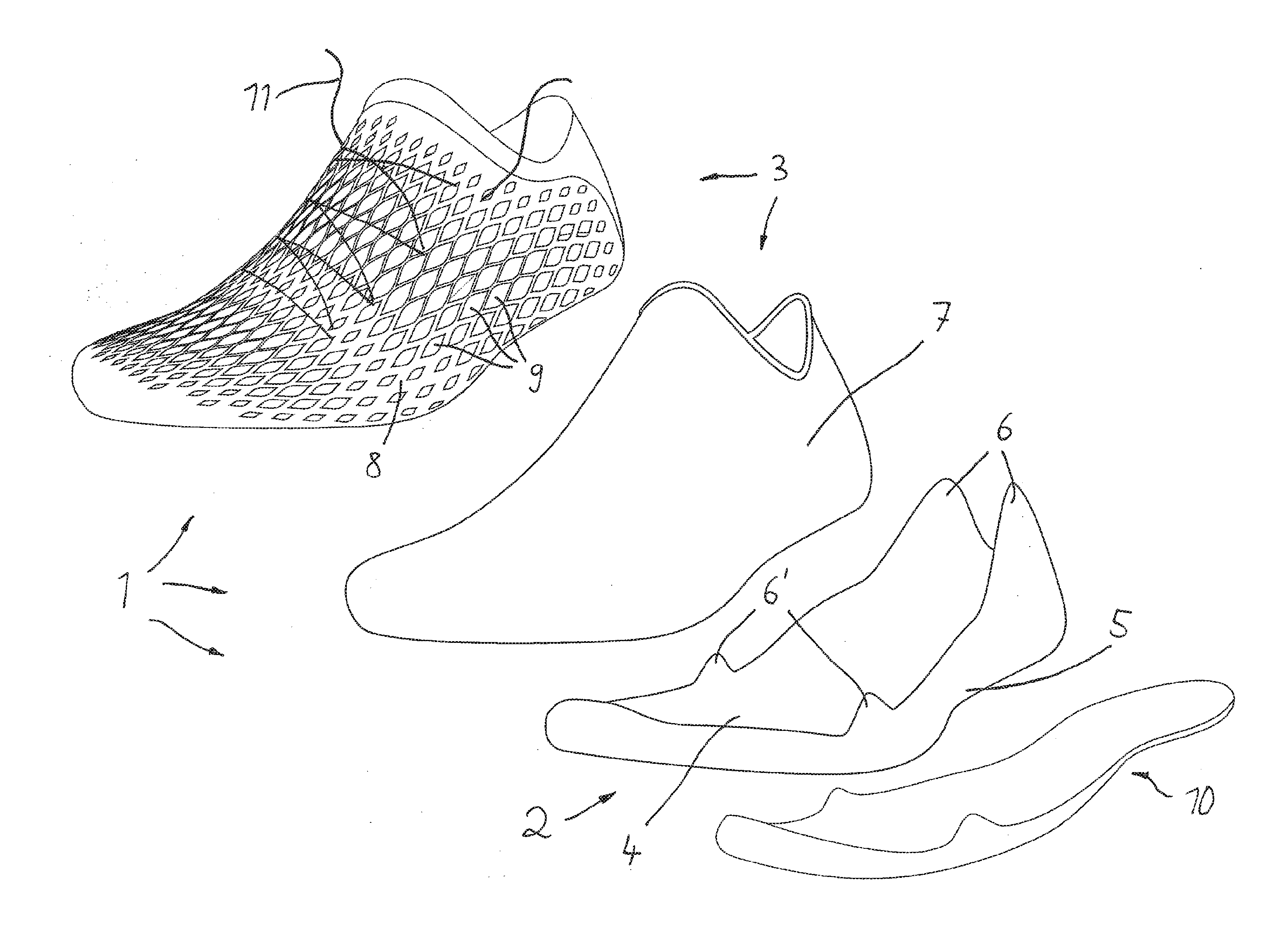
2. Shoe according to claim 1, characterized in that the tensioning element (8) is designed as net-like structure which comprises a plurality of apertures (9).
3. Shoe according to claim 2, characterized in that the tensioning element (8) is connected with the sole (2) in the bottom region of the shoe (1).
4. Shoe according to claim 3, characterized in that the tensioning element (8) runs circumferentially around the bottom side of the shoe (1).
5. Shoe according to claim 4, characterized in that the tensioning element (8) is fixed between a section of the sole and an outer sole (10) which forms the bottom end of the shoe (1).
6. Shoe according to one of claims 2 to 5, characterized in that a lace (11) is threaded into the apertures (9) of the tensioning element (8) to tension the tensioning element (8) at the foot of the wearer of the shoe (1).
7. Shoe according to one of claims 1 to 6, characterized in that an insole is arranged in the inner of the sock-like section (7).
8. Shoe according to one of claims 1 to 7, characterized in that each one support part (6) is arranged in the central or rear side region of the shoe (1).
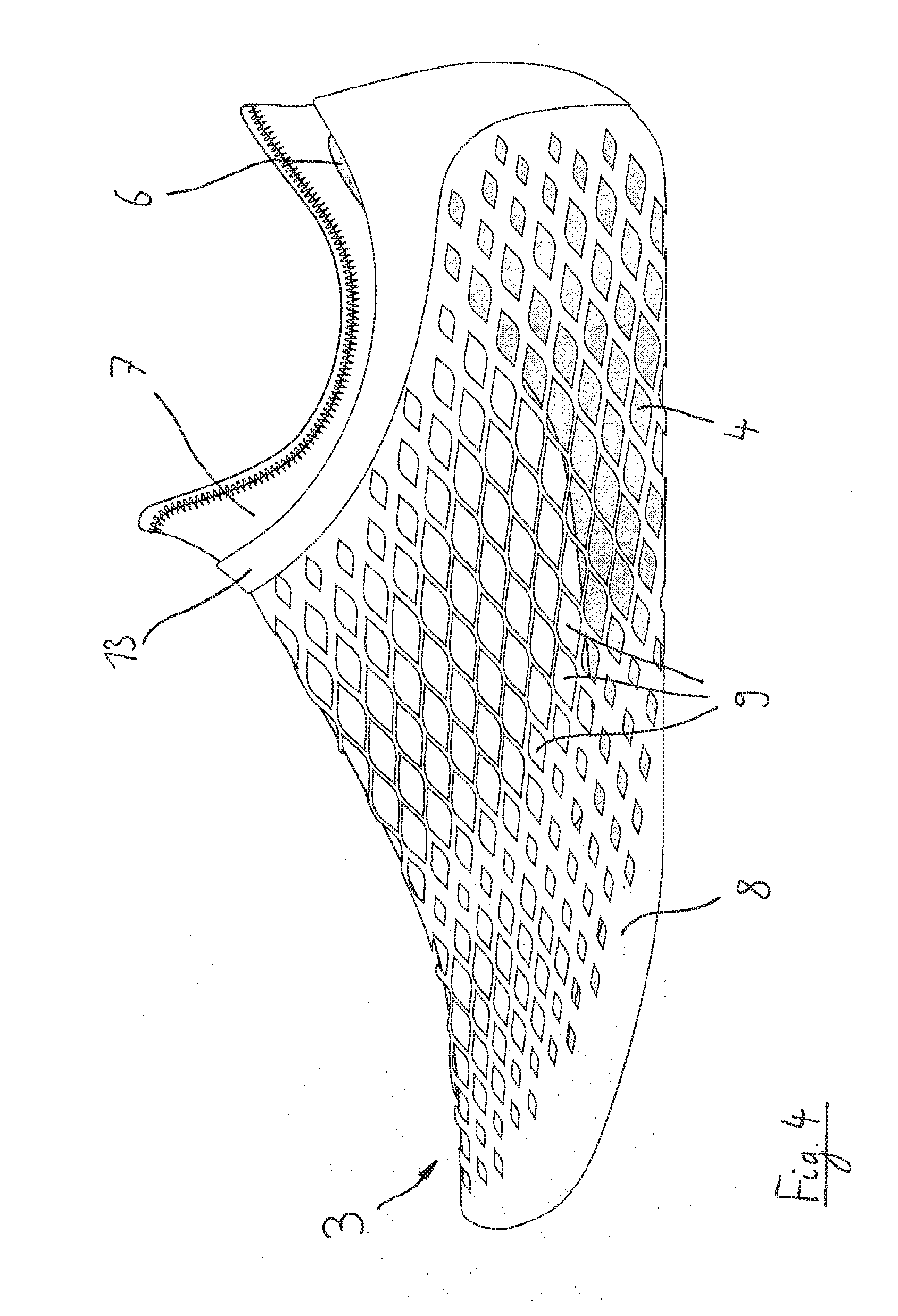
9. Shoe according to claim 8, characterized in that the support part (6) extends along a height (h) of at least 40% of the total height (H) of the shoe (1).
10. Shoe according to one of claims 1 to 9, characterized in that at least one support part (6'') is arranged in the heel region of the shoe (1).
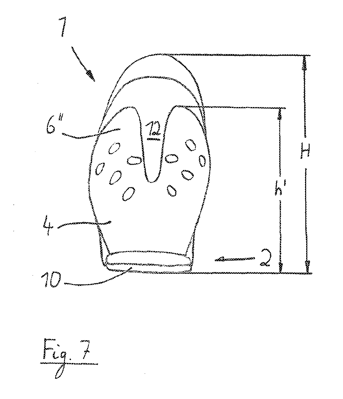
11. Shoe according to claim 10, characterized in that the support part (6'') extends along a height (h') of at least 40% of the total height (H) of the shoe (1).
12. Shoe according to claim 10 or 11, characterized in that a single support part (6'') is arranged in the heel region of the shoe (1), which comprises an insection (12) in a central region.
13. Shoe according to one of claims 1 to 12, characterized in that each one support part (6') is arranged in the front or central region of the shoe (1).
14. Shoe according to one of claims 1 to 13, characterized in that the tensioning element (8), as the case may be apart from a location in the heel region, is connected with the sole (2) only in the bottom region of the sole (2) and runs apart from that without connection around the region of the shoe upper (3).
15. Shoe according to one of claims 2 to 14, characterized in that the tensioning element (8) comprises a circumferential reinforcement rim (13) in the region of the foot entry, wherein the reinforcement rim (13) is formed by a flat plastic band.
Description
[0001] The invention relates to a shoe, in particular to a sports shoe, comprising a sole and a shoe upper, wherein the sole comprises a sole part which has a base region from which at least one support part extends upwards during the intended use of the shoe, wherein the shoe upper comprises a sock-like section connected to the sole for receiving the foot of the wearer, wherein the at least one support part covers the sock-like section on the shoe outer side, wherein no firm connection exists between the support part and the sock-like section over at least a section of the support part and wherein both the at least one support part and the sock-like section are surrounded by a tensioning element which tensions at least some sections of both the support part and the sock-like section against the foot of the wearer of the shoe.
[0002] Sports shoes of this kind are well known. Beside a base plate structure the sole part often comprises sections which extend upwards which should give the foot of the wearer a proper hold.
[0003] Furthermore, it is known to employ a sock-like section in the region of the shoe upper which widely surrounds the foot of the wearer during intended use of the shoe.
[0004] Thereby, it is a continuous concern to design the shoe in such a manner that a best contact is given at the foot of the wearer. Thereby, a uniform tension is aimed for after the lacing of the shoe at the foot of the wearer.
[0005] A shoe of the above mentioned kind is known from WO 2012/012332 A2. Similar and other solutions are shown in FR 2 999 882 A1, FR 1 228 239 A, US 2015/0089839 A1, FR 2 835 405 A1 and US 2007/180730 A1.
[0006] It is an object of the invention to further develop a shoe of the generic kind that an improved contact at the foot of the wearer can be obtained when the shoe is laced at the foot of the wearer.
[0007] The solution of this object by the invention is characterized in that the tensioning element is designed as net-like structure which comprises a plurality of apertures, wherein a lace is threaded only into the apertures of the tensioning element to tension the tensioning element at the foot of the wearer of the shoe, wherein a support part is arranged in the rear side region and/or in the heel region of the shoe, wherein the support part extends along a height of at least 40% of the total height of the shoe.
[0008] The tensioning element can thereby be connected with the sole in the bottom region of the shoe. It can run circumferentially around the bottom side of the shoe. Thereby, a preferred embodiment provides that the tensioning element is fixed between a section of the sole and an outer sole which forms the bottom end of the shoe. The fixation between the sole part, the tensioning element and the outer sole can thereby take place by glueing.
[0009] An insole can be arranged in the inner of the sock-like section.
[0010] The support part extends preferably of at least 50% of the total height of the shoe.
[0011] Here, it can further be provided that a single support part is arranged in the heel region of the shoe, which comprises an insection in a central region. Hereby, it becomes possible in a specifically beneficial manner that after lacing the shoe contacts optimal the foot of the wearer also in the heel region.
[0012] Furthermore, each one support part can be arranged in the front or central region of the shoe.
[0013] The tensioning element can thereby--as the case may be apart from a location in the heel region--be connected with the sole only in the bottom region of the sole and can run apart from that without connection around the region of the shoe upper.
[0014] The net-like designed tensioning element can comprise a circumferential reinforcement rim in the region of the foot entry; this is formed preferably by a flat plastic band.
[0015] Thus, in any case an essential feature of the present concept is at least according to a preferred embodiment of the invention that the intermediate sole (called sole part in the above explanation) is provided along certain regions--especially in the heel region and in the side region--without connection to a sock-like inner shoe, wherein the shoe is surrounded at the outer side by a net-like structure. Only by the lacing of the net-like structure the intermediate sole is pulled against the sock-like inner shoe. Hereby, an improved fit of the shoe is possible.
[0016] Thereby, the net-like structure can extend down to the sole region; it can also extend completely around the bottom side of the shoe.
[0017] So, at the proposed concept a "sock" is given in the inner region of the shoe and the shoe upper respectively which is not connected at least partially with the intermediate sole; this applies at least for the side region, in the bottom region a connection can be provided.
[0018] Only the "net" tensions then by means of a lace the intermediate sole and the "sock" at the foot.
[0019] Thereby it results beneficially that after the lacing of the shoe the same contacts optimal the foot of the wearer and a very constant distribution of pressure is obtained onto the foot of the wearer.
[0020] Furthermore, it is beneficial that this can be obtained by relative easy producible measures which can be realized in a cost-efficient manner.
[0021] In the drawing embodiments of the invention are shown.
[0022] FIG. 1 shows an explosion view of a shoe according to the invention which is designed as sports shoe,
[0023] FIG. 2 shows the side view of a sock-like section which is a part of the shoe and especially of the shoe upper,
[0024] FIG. 3 shows the side view of the sock-like section which is now inserted into a sole part,
[0025] FIG. 4 shows the side view the sole part according to FIG. 3 including sock-like section and a tensioning element which is designed as net-like structure,
[0026] FIG. 5 shows the side view of the complete shoe,
[0027] FIG. 6 shows the top plan view onto the complete shoe and
[0028] FIG. 7 shows the view of the shoe from the rear side according to a similar embodiment of the invention, wherein the sole part which supports the heel as well as other components of the shoe are depicted.
[0029] In FIG. 1 an embodiment of the shoe according to the invention is shown in an explosion view. The shoe 1 comprises a sole 2 and a shoe upper 3 which is connected with the sole 2. The sole consist here of a sole part 4 below which an outer sole 10 is arranged. The sole part 4 in turn has a base region 5 which corresponds to the shape of the foot contact area and has support parts 6 and 6' which extend vertically upwards.
[0030] The shoe upper 3 consists substantially of a sock-like section 7 which is provided for the reception of the foot of the wearer of the shoe and a tensioning element 8 in the form of a net-like structure.
[0031] The tensioning element 8 is provided due to its design as a net with a plurality of apertures 9 through which a lace 11 can be threaded to lace the shoe 1 at the foot of the wearer.
[0032] The tensioning element 8 is thereby provided to envelop the sock-like section 7 not only at its outer side but also to envelop the support parts 6, 6' at its outer side and to pull them against the foot at the lacing of the shoe at the foot of the wearer.
[0033] Thereby it is essential that the support parts 6, 6' cover the sock-like section 7 at the outer side of the shoe. Thereby, no firm connection is given between the support part 6, 6' and the sock-like section 7. Furthermore, the support parts 6, 6' as well as the sock-like section 7 is surrounded by the tensioning element 8 which tensions the support parts 6, 6' as well as the sock-like section 7 at the foot of the wearer of the shoe.
[0034] The design of the shoe can be seen again from the further figures:
[0035] In FIG. 2 the sock-like section 7 can be seen below which the sole part 4 is arranged according to FIG. 3. In FIG. 3 it can be seen again quite well how the support parts 6 and 6' extend upwards from the base region 5 of the sole part 4, wherein hereby it has to be understood that those parts extend substantially vertical upwards when the shoe stands on the ground.
[0036] In FIG. 4 can be seen how the arrangement according to FIG. 3 is now surrounded by the tensioning element 8 from the outer side and can be tensioned when the shoe is laced at the foot of the wearer. In this figure it can also be seen that the tensioning element can be provided with a reinforcement rim 13 in the region of the entry of the foot into the shoe.
[0037] This reinforcement rim 13 can be designed as foil-like thin plastic element which also makes sure that the net-like structure of the tensioning element 8 is edged in this region and cannot easily frazzle.
[0038] The finished shoe is shown in FIG. 5 (in the side view) and FIG. 6 (in the top plan view). Here it can again be seen that the height h of the support part 6 in the rear side region of the shoe has a value which corresponds to at least 50% of the total height H of the shoe 1, preferably even significantly more.
[0039] In FIG. 7 the shoe can be seen from the rear side--however not with all parts--namely in a bit different embodiment at which a support part 6'' is provided in the heel region which--as described above--is formed at the sole part 4.
[0040] The support part 6'' surrounds shell-like the heel of the foot of the wearer, but has however an insection 12 which is arranged in the center plane. Also here the height h' of the support part 6'' is denoted, wherein with respect to this the same applies as described above with respect to the support part 6.
[0041] Thereby, a preferred embodiment of the invention provides that the support part 6 is arranged along the longitudinal axis of the shoe nearly in the midst of the shoe, while a support part 6'' having an insection 12 is arranged in the heel region of the shoe.
LIST OF REFERENCES
[0042] 1 Shoe [0043] 2 Sole [0044] 3 Shoe upper [0045] 4 Sole part [0046] 5 Base region [0047] 6 Support part [0048] 6' Support part [0049] 6'' Support part [0050] 7 Sock-like section [0051] 8 Tensioning element (net-like structure) [0052] 9 Aperture [0053] 10 Outer sole [0054] 11 Lace [0055] 12 Insection [0056] 13 Reinforcement rim [0057] H Total height of the shoe [0058] h Height of the support part [0059] h' Height of the support part
* * * * *
D00000
D00001
D00002
D00003
D00004
D00005
XML
uspto.report is an independent third-party trademark research tool that is not affiliated, endorsed, or sponsored by the United States Patent and Trademark Office (USPTO) or any other governmental organization. The information provided by uspto.report is based on publicly available data at the time of writing and is intended for informational purposes only.
While we strive to provide accurate and up-to-date information, we do not guarantee the accuracy, completeness, reliability, or suitability of the information displayed on this site. The use of this site is at your own risk. Any reliance you place on such information is therefore strictly at your own risk.
All official trademark data, including owner information, should be verified by visiting the official USPTO website at www.uspto.gov. This site is not intended to replace professional legal advice and should not be used as a substitute for consulting with a legal professional who is knowledgeable about trademark law.