Resource Configuration Of Beam Failure Recovery Request Transmission
Zhou; Hua ; et al.
U.S. patent application number 16/101239 was filed with the patent office on 2019-02-14 for resource configuration of beam failure recovery request transmission. The applicant listed for this patent is Comcast Cable Communications, LLC. Invention is credited to Alireza Babaei, Esmael Hejazi Dinan, Hyoungsuk Jeon, Kyungmin Park, Hua Zhou.
| Application Number | 20190053288 16/101239 |
| Document ID | / |
| Family ID | 65274328 |
| Filed Date | 2019-02-14 |


View All Diagrams
| United States Patent Application | 20190053288 |
| Kind Code | A1 |
| Zhou; Hua ; et al. | February 14, 2019 |
RESOURCE CONFIGURATION OF BEAM FAILURE RECOVERY REQUEST TRANSMISSION
Abstract
Systems, apparatuses, and methods are described for wireless communications. A wireless device may select a reference signal and/or random access channel resource based on configuration parameters for a beam failure recovery procedure. A base station may send configuration parameters using a medium access control (MAC) control element (CE).
| Inventors: | Zhou; Hua; (Herndon, VA) ; Dinan; Esmael Hejazi; (Herndon, VA) ; Park; Kyungmin; (Arlington, VA) ; Jeon; Hyoungsuk; (Oakton, VA) ; Babaei; Alireza; (Fairfax, VA) | ||||||||||
| Applicant: |
|
||||||||||
|---|---|---|---|---|---|---|---|---|---|---|---|
| Family ID: | 65274328 | ||||||||||
| Appl. No.: | 16/101239 | ||||||||||
| Filed: | August 10, 2018 |
Related U.S. Patent Documents
| Application Number | Filing Date | Patent Number | ||
|---|---|---|---|---|
| 62543820 | Aug 10, 2017 | |||
| Current U.S. Class: | 1/1 |
| Current CPC Class: | H04B 17/17 20150115; H04W 74/006 20130101; H04W 74/0833 20130101; H04L 27/2692 20130101; H04B 7/0626 20130101; H04B 17/309 20150115; H04W 76/27 20180201; H04L 5/0091 20130101; H04B 7/0695 20130101 |
| International Class: | H04W 74/08 20060101 H04W074/08; H04B 7/06 20060101 H04B007/06; H04L 27/26 20060101 H04L027/26; H04B 17/309 20060101 H04B017/309; H04W 76/27 20060101 H04W076/27 |
Claims
1. A method comprising: receiving, by a wireless device, one or more radio resource control messages comprising configuration parameters of a cell, wherein the configuration parameters comprise: one or more parameters of a plurality of reference signals; and one or more parameters of a plurality of random access channel (RACH) resources; receiving at least one medium access control (MAC) control element comprising an indication to activate at least one of: a first reference signal of the plurality of reference signals; or a first RACH resource of the plurality of RACH resources; detecting at least one beam failure; selecting, after the detecting the at least one beam failure, a preamble associated with the first RACH resource; and transmitting, via the first RACH resource, the selected preamble.
2. The method of claim 1, wherein the detecting the at least one beam failure comprises measuring a channel state information reference signal resource associated with the plurality of reference signals.
3. The method of claim 1, wherein the transmitting the selected preamble comprises transmitting a beam failure recovery request with the selected preamble.
4. The method of claim 1, further comprising monitoring a plurality of second reference signals indicated by the at least one MAC control element, wherein the first RACH resource is associated with one or more of the plurality of second reference signals.
5. The method of claim 1, wherein the configuration parameters further comprise one or more thresholds, and wherein the detecting the at least one beam failure comprises: determining that a channel quality of the first reference signal is below a first threshold of the one or more thresholds.
6. A method comprising: transmitting, by a base station, one or more radio resource control messages comprising configuration parameters of a cell, wherein the configuration parameters comprise: one or more parameters of a plurality of reference signals; and one or more parameters of a plurality of random access channel (RACH) resources; transmitting, by the base station to a wireless device, at least one medium access control (MAC) control element comprising an indication to activate at least one of: a first reference signal of the plurality of reference signals; or a first RACH resource of the plurality of RACH resources; and receiving, from the wireless device via the first RACH resource, a preamble, wherein the preamble is based on a channel quality of the first reference signal.
7. The method of claim 6, wherein the one or more parameters of the plurality of reference signals comprises a channel state information reference signal resource.
8. The method of claim 6, wherein the receiving the preamble comprises receiving a beam failure recovery request with the preamble.
9. The method of claim 6, further comprising: determining a plurality of sets of second reference signals; and transmitting one or more indications of the plurality of sets of second reference signals, wherein the first RACH resource is associated with a first candidate beam in a first set of the plurality of sets of second reference signals, and wherein the plurality of sets of second reference signals is indicated by the at least one MAC control element.
10. The method of claim 6, wherein the configuration parameters further comprise one or more thresholds.
11. A wireless device comprising: one or more processors; and memory storing instructions that, when executed by the one or more processors, cause the wireless device to: receive one or more radio resource control messages comprising configuration parameters of a cell, wherein the configuration parameters comprise: one or more parameters of a plurality of reference signals; and one or more parameters of a plurality of random access channel (RACH) resources; receive at least one medium access control (MAC) control element comprising an indication to activate at least one of: a first reference signal of the plurality of reference signals; or a first RACH resource of the plurality of RACH resources; detect at least one beam failure; select, after the detecting the at least one beam failure, a preamble associated with the first RACH resource; and transmit, via the first RACH resource, the selected preamble.
12. The wireless device of claim 11, wherein the instructions, when executed by the one or more processors, cause the wireless device to detect the at least one beam failure by measuring a channel state information reference signal resource associated with the plurality of reference signals.
13. The wireless device of claim 11, wherein the instructions, when executed by the one or more processors, cause the wireless device to transmit the selected preamble by transmitting a beam failure recovery request with the selected preamble.
14. The wireless device of claim 11, wherein the instructions, when executed by the one or more processors, cause the wireless device to monitor a plurality of second reference signals indicated by the at least one MAC control element, wherein the first RACH resource is associated with one or more of the plurality of second reference signals.
15. The wireless device of claim 11, wherein the configuration parameters further comprise one or more thresholds, and wherein the instructions, when executed by the one or more processors, cause the wireless device to detect the at least one beam failure by: determining that a channel quality of the first reference signal is below a first threshold of the one or more thresholds.
16. A base station comprising: one or more processors; and memory storing instructions that, when executed by the one or more processors, cause the base station to: transmit one or more radio resource control messages comprising configuration parameters of a cell, wherein the configuration parameters comprise: one or more parameters of a plurality of reference signals; and one or more parameters of a plurality of random access channel (RACH) resources; transmit, to a wireless device, at least one medium access control (MAC) control element comprising an indication to activate at least one of: a first reference signal of the plurality of reference signals; or a first RACH resource of the plurality of RACH resources; and receive, from the wireless device via the first RACH resource, a preamble, wherein the preamble is based on a channel quality of the first reference signal.
17. The base station of claim 16, wherein the one or more parameters of the plurality of reference signals comprises a channel state information reference signal resource.
18. The base station of claim 16, wherein the instructions, when executed by the one or more processors, cause the base station to receive the preamble by receiving a beam failure recovery request with the preamble.
19. The base station of claim 16, wherein the instructions, when executed by the one or more processors, cause the base station to: determine a plurality of sets of second reference signals; and transmit one or more indications of the plurality of sets of second reference signals, wherein the first RACH resource is associated with a first candidate beam in a first set of the plurality of sets of second reference signals, and wherein the plurality of sets of second reference signals is indicated by the at least one MAC control element.
20. The base station of claim 16, wherein the configuration parameters further comprise one or more thresholds.
Description
CROSS-REFERENCE TO RELATED APPLICATIONS
[0001] This application claims the benefit of U.S. Provisional Application No. 62/543,820, titled "Resource Configuration of BFR Request," which was filed on Aug. 10, 2017, and which is hereby incorporated by reference in its entirety.
BACKGROUND
[0002] In wireless communications, beam failure recovery may be used for recovering a beam pair link between a base station and a wireless device. If a beam failure is detected, difficulties may arise in performing beam failure recovery in a timely and efficient manner.
SUMMARY
[0003] The following summary presents a simplified summary of certain features. The summary is not an extensive overview and is not intended to identify key or critical elements.
[0004] Systems, apparatuses, and methods are described for communications associated with beam failure recovery. A base station may transmit, to a wireless device, one or more messages comprising configuration parameters for beam failure recovery. The configuration parameters may comprise an indication of reference signals and/or channel resources to be used in beam failure recovery. The configuration parameters may be transmitted using a medium access control (MAC) control element (CE). The wireless device may detect a beam failure. The wireless device and/or the base station may utilize the reference signals and/or channel resources in performing a beam failure recovery procedure.
[0005] These and other features and advantages are described in greater detail below.
BRIEF DESCRIPTION OF THE DRAWINGS
[0006] Some features are shown by way of example, and not by limitation, in the accompanying drawings. In the drawings, like numerals reference similar elements.
[0007] FIG. 1 shows example sets of orthogonal frequency division multiplexing (OFDM) subcarriers.
[0008] FIG. 2 shows example transmission time and reception time for two carriers in a carrier group.
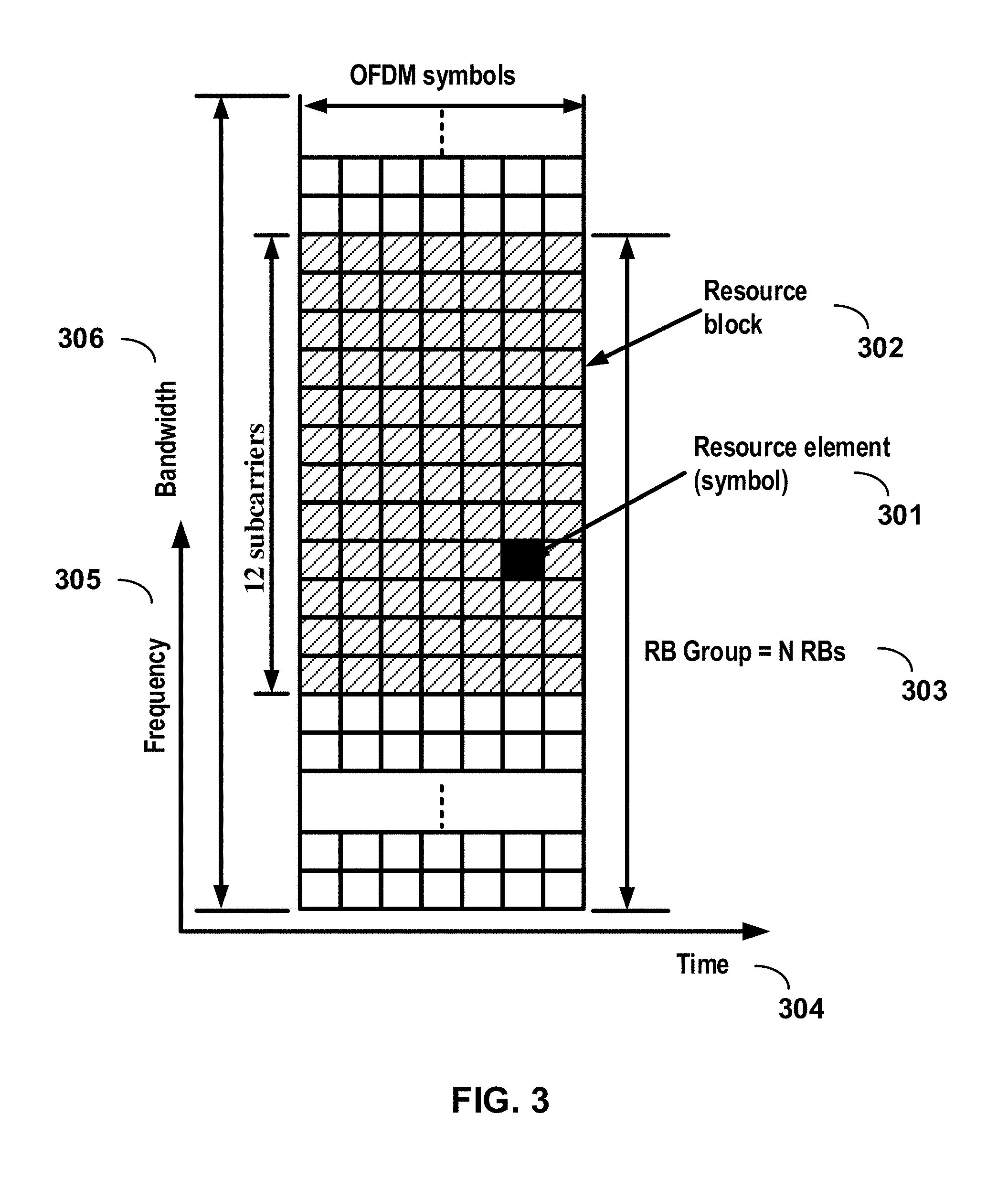
[0009] FIG. 3 shows example OFDM radio resources.
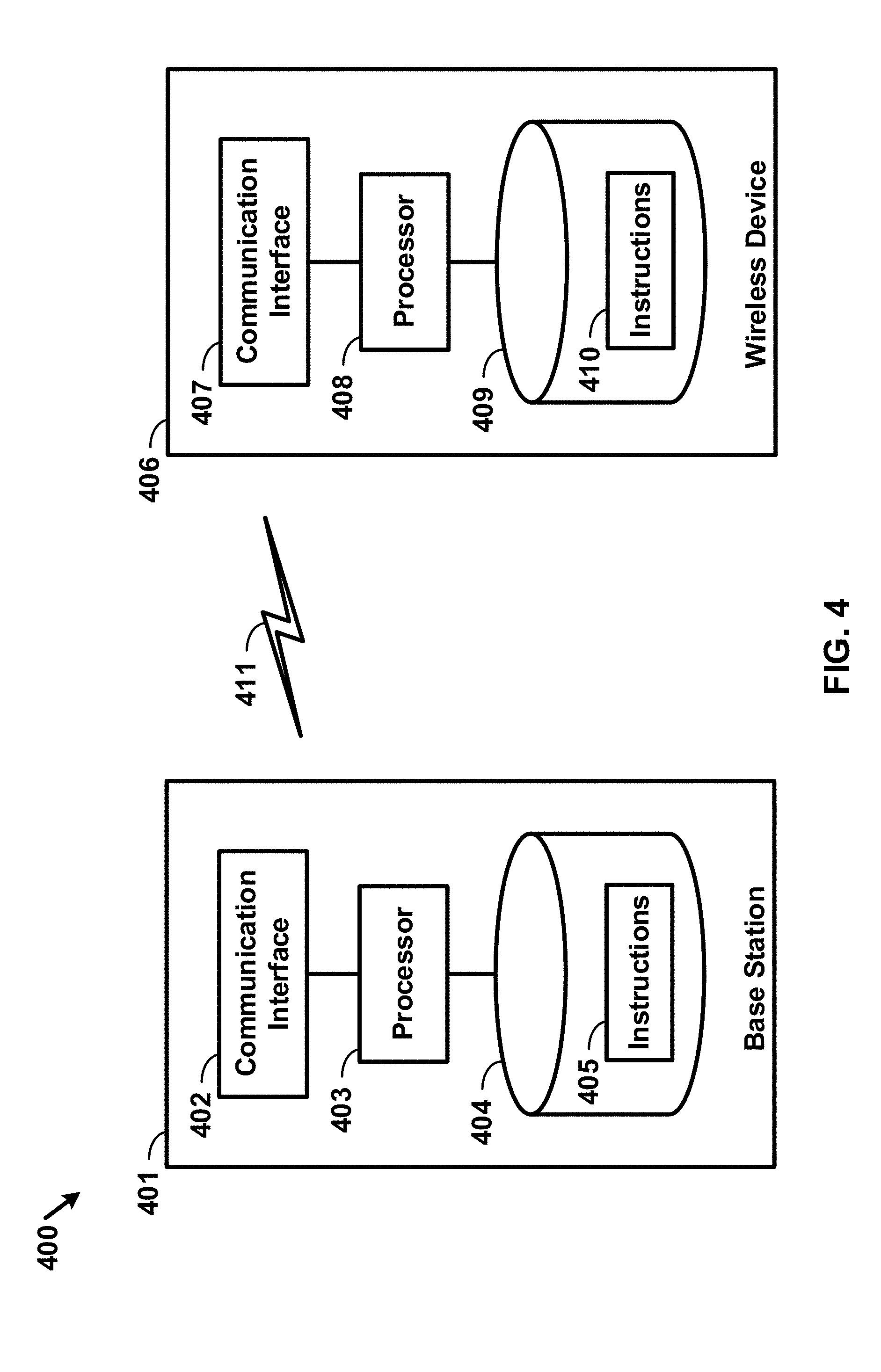
[0010] FIG. 4 shows hardware elements of a base station and a wireless device.
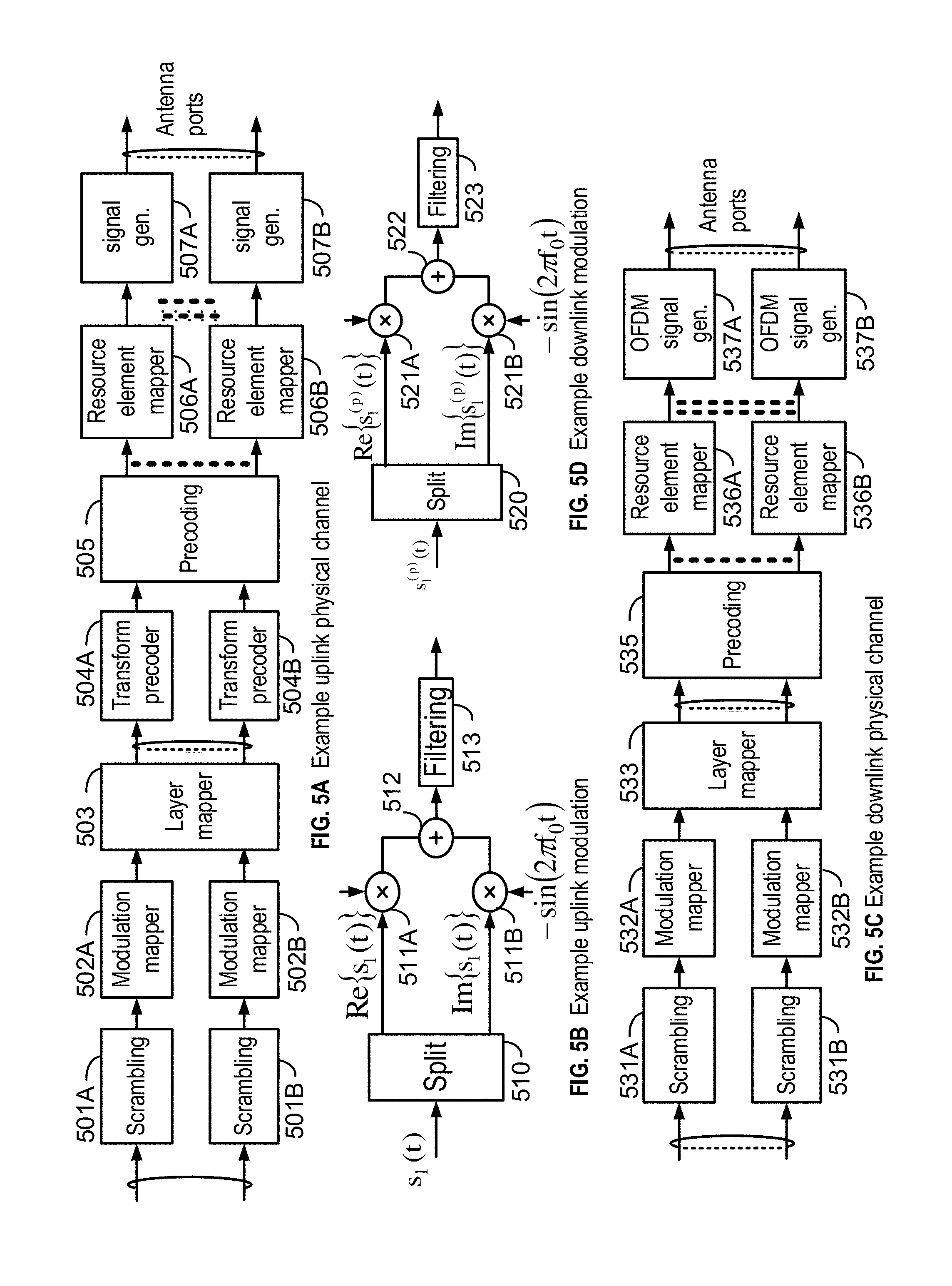
[0011] FIG. 5A, FIG. 5B, FIG. 5C and FIG. 5D show examples for uplink and downlink signal transmission.
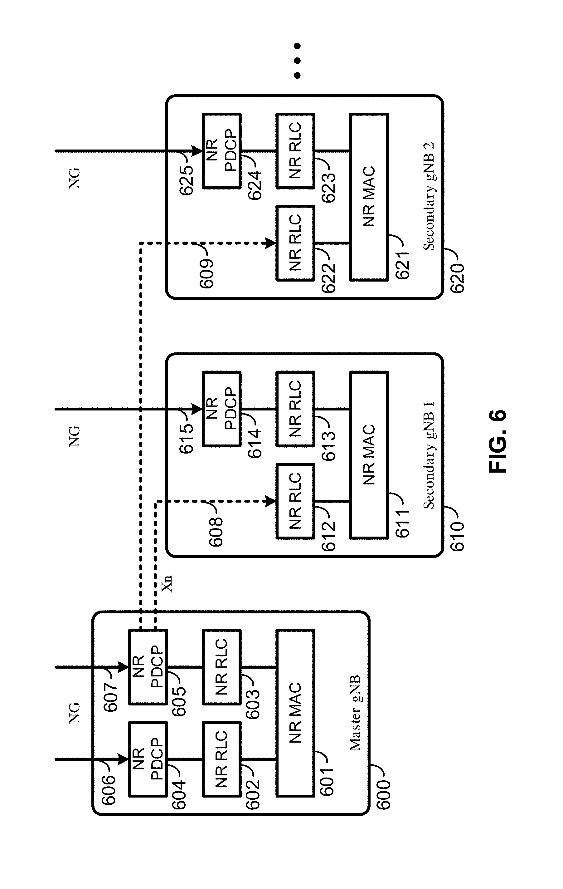
[0012] FIG. 6 shows an example protocol structure with multi-connectivity.
[0013] FIG. 7 shows an example protocol structure with carrier aggregation (CA) and dual connectivity (DC).
[0014] FIG. 8 shows example timing advance group (TAG) configurations.
[0015] FIG. 9 shows example message flow in a random access process in a secondary TAG.
[0016] FIG. 10A and FIG. 10B show examples for interfaces between a 5G core network and base stations.
[0017] FIG. 11A, FIG. 11B, FIG. 11C, FIG. 11D, FIG. 11E, and FIG. 11F show examples for architectures of tight interworking between a 5G RAN and a long term evolution (LTE) radio access network (RAN).
[0018] FIG. 12A, FIG. 12B, and FIG. 12C show examples for radio protocol structures of tight interworking bearers.
[0019] FIG. 13A and FIG. 13B show examples for gNodeB (gNB) deployment.
[0020] FIG. 14 shows functional split option examples of a centralized gNB deployment.
[0021] FIG. 15 shows an example of a synchronization signal burst set.
[0022] FIG. 16 shows an example of a random access procedure.
[0023] FIG. 17 shows an example of transmitting channel state information reference signals periodically for a beam.
[0024] FIG. 18 shows an example of a channel state information reference signal mapping.
[0025] FIG. 19 shows an example of a beam failure event involving a single transmission and receiving point.
[0026] FIG. 20 shows an example of a beam failure event involving multiple transmission and receiving points.
[0027] FIG. 21 shows an example of a beam failure recovery request utilizing a PRACH channel.
[0028] FIG. 22 shows an example of a multi-beam BFR-PRACH configuration.
[0029] FIG. 23 shows an example of a multi-beam BFR-PRACH configuration.
[0030] FIG. 24 shows an example of a PRACH configuration for a beam failure recovery request transmission.
[0031] FIG. 25 shows an example of MAC signaling activating a subset of a configured CSI-RS associated with a BFR-PRACH resource.
[0032] FIG. 26 shows an example of PRACH configuration and activation for a beam failure recovery request transmission.
[0033] FIG. 27 shows an example MAC CE structure for CSI-RS and/or BFR-PRACH activation or deactivation.
[0034] FIG. 28 shows an example of PRACH configuration and activation for BFR request transmission.
[0035] FIG. 29 shows an example MAC CE for CSI-RS activation and/or deactivation, and/or BFR-PRACH configuration.
[0036] FIG. 30 shows an example of processes for a wireless device for beam failure recovery requests.
[0037] FIG. 31 shows an example of processes for a base station for beam failure recovery requests.
[0038] FIG. 32 shows example elements of a computing device that may be used to implement any of the various devices described herein.
DETAILED DESCRIPTION
[0039] The accompanying drawings, which form a part hereof, show examples of the disclosure. It is to be understood that the examples shown in the drawings and/or discussed herein are non-exclusive and that there are other examples of how the disclosure may be practiced.
[0040] Examples may enable operation of carrier aggregation and may be employed in the technical field of multicarrier communication systems. Examples may relate to beam management in a multicarrier communication system.
[0041] The following acronyms are used throughout the present disclosure, provided below for convenience although other acronyms may be introduced in the detailed description: [0042] 3GPP 3rd Generation Partnership Project [0043] 5G 5th generation wireless systems [0044] 5GC 5G Core Network [0045] ACK Acknowledgement [0046] AMF Access and Mobility Management Function [0047] ASIC application-specific integrated circuit [0048] BFR beam failure recovery [0049] BPSK binary phase shift keying [0050] CA carrier aggregation [0051] CC component carrier [0052] CDMA code division multiple access [0053] CP cyclic prefix [0054] CPLD complex programmable logic devices [0055] CSI channel state information [0056] CSS common search space [0057] CU central unit [0058] DC dual connectivity [0059] DCI downlink control information [0060] DFTS-OFDM discrete fourier transform spreading OFDM [0061] DL downlink [0062] DU distributed unit [0063] eLTE enhanced LTE [0064] eMBB enhanced mobile broadband [0065] eNB evolved Node B [0066] EPC evolved packet core [0067] E-UTRAN evolved-universal terrestrial radio access network [0068] FDD frequency division multiplexing [0069] FPGA field programmable gate arrays [0070] Fs-C Fs-control plane [0071] Fs-U Fs-user plane [0072] gNB next generation node B [0073] HARQ hybrid automatic repeat request [0074] HDL hardware description languages [0075] ID identifier [0076] IE information element [0077] LTE long term evolution [0078] MAC media access control [0079] MCG master cell group [0080] MeNB master evolved node B [0081] MIB master information block [0082] MME mobility management entity [0083] mMTC massive machine type communications [0084] NACK Negative Acknowledgement [0085] NAS non-access stratum [0086] NG CP next generation control plane core [0087] NGC next generation core [0088] NG-C NG-control plane [0089] NG-U NG-user plane [0090] NR MAC new radio MAC [0091] NR PDCP new radio PDCP [0092] NR PHY new radio physical [0093] NR RLC new radio RLC [0094] NR RRC new radio RRC [0095] NR new radio [0096] NSS AI network slice selection assistance information [0097] OFDM orthogonal frequency division multiplexing [0098] PCC primary component carrier [0099] PCell primary cell [0100] PDCCH physical downlink control channel [0101] PDCP packet data convergence protocol [0102] PDU packet data unit [0103] PHICH physical HARQ indicator channel [0104] PHY physical [0105] PLMN public land mobile network [0106] PSCell primary secondary cell [0107] pTAG primary timing advance group [0108] PUCCH physical uplink control channel [0109] PUSCH physical uplink shared channel [0110] QAM quadrature amplitude modulation [0111] QPSK quadrature phase shift keying [0112] RA random access [0113] RACH random access channel [0114] RAN radio access network [0115] RAP random access preamble [0116] RAR random access response [0117] RB resource blocks [0118] RBG resource block groups [0119] RLC radio link control [0120] RRC radio resource control [0121] RRM radio resource management [0122] RV redundancy version [0123] SCC secondary component carrier [0124] SCell secondary cell [0125] SCG secondary cell group [0126] SC-OFDM single carrier-OFDM [0127] SDU service data unit [0128] SeNB secondary evolved node B [0129] SFN system frame number [0130] S-GW serving gateway [0131] SIB system information block [0132] SC-OFDM single carrier orthogonal frequency division multiplexing [0133] SRB signaling radio bearer [0134] sTAG(s) secondary timing advance group(s) [0135] TA timing advance [0136] TAG timing advance group [0137] TAI tracking area identifier [0138] TAT time alignment timer [0139] TDD time division duplexing [0140] TDMA time division multiple access [0141] TTI transmission time interval [0142] TB transport block [0143] UE user equipment [0144] UL uplink [0145] UPGW user plane gateway [0146] URLLC ultra-reliable low-latency communications [0147] VHDL VHSIC hardware description language [0148] Xn-C Xn-control plane [0149] Xn-U Xn-user plane [0150] Xx-C Xx-control plane [0151] Xx-U Xx-user plane
[0152] Examples may be implemented using various physical layer modulation and transmission mechanisms. Example transmission mechanisms may include, but are not limited to: CDMA, OFDM, TDMA, Wavelet technologies, and/or the like. Hybrid transmission mechanisms such as TDMA/CDMA, and OFDM/CDMA may also be employed. Various modulation schemes may be used for signal transmission in the physical layer. Examples of modulation schemes include, but are not limited to: phase, amplitude, code, a combination of these, and/or the like. An example radio transmission method may implement QAM using BPSK, QPSK, 16-QAM, 64-QAM, 256-QAM, and/or the like. Physical radio transmission may be enhanced by dynamically or semi-dynamically changing the modulation and coding scheme depending on transmission requirements and radio conditions.
[0153] FIG. 1 shows example sets of OFDM subcarriers. As shown in this example, arrow(s) in the diagram may depict a subcarrier in a multicarrier OFDM system. The OFDM system may use technology such as OFDM technology, DFTS-OFDM, SC-OFDM technology, or the like. For example, arrow 101 shows a subcarrier transmitting information symbols. FIG. 1 is shown as an example, and a typical multicarrier OFDM system may include more subcarriers in a carrier. For example, the number of subcarriers in a carrier may be in the range of 10 to 10,000 subcarriers. FIG. 1 shows two guard bands 106 and 107 in a transmission band. As shown in FIG. 1, guard band 106 is between subcarriers 103 and subcarriers 104. The example set of subcarriers A 102 includes subcarriers 103 and subcarriers 104. FIG. 1 also shows an example set of subcarriers B 105. As shown, there is no guard band between any two subcarriers in the example set of subcarriers B 105. Carriers in a multicarrier OFDM communication system may be contiguous carriers, non-contiguous carriers, or a combination of both contiguous and non-contiguous carriers.
[0154] FIG. 2 shows an example timing arrangement with transmission time and reception time for two carriers. A multicarrier OFDM communication system may include one or more carriers, for example, ranging from 1 to 10 carriers. Carrier A 204 and carrier B 205 may have the same or different timing structures. Although FIG. 2 shows two synchronized carriers, carrier A 204 and carrier B 205 may or may not be synchronized with each other. Different radio frame structures may be supported for FDD and TDD duplex mechanisms. FIG. 2 shows an example FDD frame timing. Downlink and uplink transmissions may be organized into radio frames 201. In this example, radio frame duration is 10 milliseconds (msec). Other frame durations, for example, in the range of 1 to 100 msec may also be supported. In this example, each 10 msec radio frame 201 may be divided into ten equally sized subframes 202. Other subframe durations such as including 0.5 msec, 1 msec, 2 msec, and 5 msec may also be supported. Subframe(s) may consist of two or more slots (e.g., slots 206 and 207). For the example of FDD, 10 subframes may be available for downlink transmission and 10 subframes may be available for uplink transmissions in each 10 msec interval. Uplink and downlink transmissions may be separated in the frequency domain. A slot may be 7 or 14 OFDM symbols for the same subcarrier spacing of up to 60 kHz with normal CP. A slot may be 14 OFDM symbols for the same subcarrier spacing higher than 60 kHz with normal CP. A slot may include all downlink, all uplink, or a downlink part and an uplink part, and/or alike. Slot aggregation may be supported, e.g., data transmission may be scheduled to span one or multiple slots. For example, a mini-slot may start at an OFDM symbol in a subframe. A mini-slot may have a duration of one or more OFDM symbols. Slot(s) may include a plurality of OFDM symbols 203. The number of OFDM symbols 203 in a slot 206 may depend on the cyclic prefix length and subcarrier spacing.
[0155] FIG. 3 shows an example of OFDM radio resources, including a resource grid structure in time 304 and frequency 305. The quantity of downlink subcarriers or RBs may depend, at least in part, on the downlink transmission bandwidth 306 configured in the cell. The smallest radio resource unit may be called a resource element (e.g., 301). Resource elements may be grouped into resource blocks (e.g., 302). Resource blocks may be grouped into larger radio resources called Resource Block Groups (RBG) (e.g., 303). The transmitted signal in slot 206 may be described by one or several resource grids of a plurality of subcarriers and a plurality of OFDM symbols. Resource blocks may be used to describe the mapping of certain physical channels to resource elements. Other pre-defined groupings of physical resource elements may be implemented in the system depending on the radio technology. For example, 24 subcarriers may be grouped as a radio block for a duration of 5 msec. A resource block may correspond to one slot in the time domain and 180 kHz in the frequency domain (for 15 kHz subcarrier bandwidth and 12 subcarriers).
[0156] Multiple numerologies may be supported. A numerology may be derived by scaling a basic subcarrier spacing by an integer N. Scalable numerology may allow at least from 15 kHz to 480 kHz subcarrier spacing. The numerology with 15 kHz and scaled numerology with different subcarrier spacing with the same CP overhead may align at a symbol boundary every 1 msec in a NR carrier.
[0157] FIG. 4 shows hardware elements of a base station 401 and a wireless device 406. A communication network 400 may include at least one base station 401 and at least one wireless device 406. The base station 401 may include at least one communication interface 402, one or more processors 403, and at least one set of program code instructions 405 stored in non-transitory memory 404 and executable by the one or more processors 403. The wireless device 406 may include at least one communication interface 407, one or more processors 408, and at least one set of program code instructions 410 stored in non-transitory memory 409 and executable by the one or more processors 408. A communication interface 402 in the base station 401 may be configured to engage in communication with a communication interface 407 in the wireless device 406, such as via a communication path that includes at least one wireless link 411. The wireless link 411 may be a bi-directional link. The communication interface 407 in the wireless device 406 may also be configured to engage in communication with the communication interface 402 in the base station 401. The base station 401 and the wireless device 406 may be configured to send and receive data over the wireless link 411 using multiple frequency carriers. Base stations, wireless devices, and other communication devices may include structure and operations of transceiver(s). A transceiver is a device that includes both a transmitter and receiver. Transceivers may be employed in devices such as wireless devices, base stations, relay nodes, and/or the like. Examples for radio technology implemented in the communication interfaces 402, 407 and the wireless link 411 are shown in FIG. 1, FIG. 2, FIG. 3, FIG. 5, and associated text. The communication network 400 may comprise any number and/or type of devices, such as, for example, computing devices, wireless devices, mobile devices, handsets, tablets, laptops, internet of things (IoT) devices, hotspots, cellular repeaters, computing devices, and/or, more generally, user equipment (e.g., UE). Although one or more of the above types of devices may be referenced herein (e.g., UE, wireless device, computing device, etc.), it should be understood that any device herein may comprise any one or more of the above types of devices or similar devices. The communication network 400, and any other network referenced herein, may comprise an LTE network, a 5G network, or any other network for wireless communications. Apparatuses, systems, and/or methods described herein may generally be described as implemented on one or more devices (e.g., wireless device, base station, eNB, gNB, computing device, etc.), in one or more networks, but it will be understood that one or more features and steps may be implemented on any device and/or in any network. As used throughout, the term "base station" may comprise one or more of: a base station, a node, a Node B, a gNB, an eNB, an ng-eNB, a relay node (e.g., an integrated access and backhaul (IAB) node), a donor node (e.g., a donor eNB, a donor gNB, etc.), an access point (e.g., a WiFi access point), a computing device, a device capable of wirelessly communicating, or any other device capable of sending and/or receiving signals. As used throughout, the term "wireless device" may comprise one or more of: a UE, a handset, a mobile device, a computing device, a node, a device capable of wirelessly communicating, or any other device capable of sending and/or receiving signals. Any reference to one or more of these terms/devices also considers use of any other term/device mentioned above.
[0158] The communications network 400 may comprise Radio Access Network (RAN) architecture. The RAN architecture may comprise one or more RAN nodes that may be a next generation Node B (gNB) (e.g., 401) providing New Radio (NR) user plane and control plane protocol terminations towards a first wireless device (e.g. 406). A RAN node may be a next generation evolved Node B (ng-eNB), providing Evolved UMTS Terrestrial Radio Access (E-UTRA) user plane and control plane protocol terminations towards a second wireless device. The first wireless device may communicate with a gNB over a Uu interface. The second wireless device may communicate with a ng-eNB over a Uu interface. Base station 401 may comprise one or more of a gNB, ng-eNB, and/or the like.
[0159] A gNB or an ng-eNB may host functions such as: radio resource management and scheduling, IP header compression, encryption and integrity protection of data, selection of Access and Mobility Management Function (AMF) at User Equipment (UE) attachment, routing of user plane and control plane data, connection setup and release, scheduling and transmission of paging messages (originated from the AMF), scheduling and transmission of system broadcast information (originated from the AMF or Operation and Maintenance (O&M)), measurement and measurement reporting configuration, transport level packet marking in the uplink, session management, support of network slicing, Quality of Service (QoS) flow management and mapping to data radio bearers, support of wireless devices in RRC_INACTIVE state, distribution function for Non-Access Stratum (NAS) messages, RAN sharing, and dual connectivity or tight interworking between NR and E-UTRA.
[0160] One or more gNBs and/or one or more ng-eNBs may be interconnected with each other by means of Xn interface. A gNB or an ng-eNB may be connected by means of NG interfaces to 5G Core Network (5GC). 5GC may comprise one or more AMF/User Plane Function (UPF) functions. A gNB or an ng-eNB may be connected to a UPF by means of an NG-User plane (NG-U) interface. The NG-U interface may provide delivery (e.g., non-guaranteed delivery) of user plane Protocol Data Units (PDUs) between a RAN node and the UPF. A gNB or an ng-eNB may be connected to an AMF by means of an NG-Control plane (e.g., NG-C) interface. The NG-C interface may provide functions such as NG interface management, UE context management, UE mobility management, transport of NAS messages, paging, PDU session management, configuration transfer or warning message transmission.
[0161] A UPF may host functions such as anchor point for intra-/inter-Radio Access Technology (RAT) mobility (if applicable), external PDU session point of interconnect to data network, packet routing and forwarding, packet inspection and user plane part of policy rule enforcement, traffic usage reporting, uplink classifier to support routing traffic flows to a data network, branching point to support multi-homed PDU session, QoS handling for user plane, e.g. packet filtering, gating, Uplink (UL)/Downlink (DL) rate enforcement, uplink traffic verification (e.g. Service Data Flow (SDF) to QoS flow mapping), downlink packet buffering and/or downlink data notification triggering.
[0162] An AMF may host functions such as NAS signaling termination, NAS signaling security, Access Stratum (AS) security control, inter Core Network (CN) node signaling for mobility between 3.sup.rd Generation Partnership Project (3GPP) access networks, idle mode UE reachability (e.g., control and execution of paging retransmission), registration area management, support of intra-system and inter-system mobility, access authentication, access authorization including check of roaming rights, mobility management control (subscription and policies), support of network slicing and/or Session Management Function (SMF) selection
[0163] An interface may be a hardware interface, a firmware interface, a software interface, and/or a combination thereof. The hardware interface may include connectors, wires, electronic devices such as drivers, amplifiers, and/or the like. A software interface may include code stored in a memory device to implement protocol(s), protocol layers, communication drivers, device drivers, combinations thereof, and/or the like. A firmware interface may include a combination of embedded hardware and code stored in and/or in communication with a memory device to implement connections, electronic device operations, protocol(s), protocol layers, communication drivers, device drivers, hardware operations, combinations thereof, and/or the like.
[0164] The term configured may relate to the capacity of a device whether the device is in an operational or a non-operational state. Configured may also refer to specific settings in a device that effect the operational characteristics of the device whether the device is in an operational or a non-operational state. In other words, the hardware, software, firmware, registers, memory values, and/or the like may be "configured" within a device, whether the device is in an operational or a nonoperational state, to provide the device with specific characteristics. Terms such as "a control message to cause in a device" may mean that a control message has parameters that may be used to configure specific characteristics in the device, whether the device is in an operational or a non-operational state.
[0165] A 5G network may include a multitude of base stations, providing a user plane NR PDCP/NR RLC/NR MAC/NR PHY and control plane (NR RRC) protocol terminations towards the wireless device. The base station(s) may be interconnected with other base station(s) (e.g., employing an Xn interface). The base stations may also be connected employing, for example, an NG interface to an NGC. FIG. 10A and FIG. 10B show examples for interfaces between a 5G core network (e.g., NGC) and base stations (e.g., gNB and eLTE eNB). For example, the base stations may be interconnected to the NGC control plane (e.g., NG CP) employing the NG-C interface and to the NGC user plane (e.g., UPGW) employing the NG-U interface. The NG interface may support a many-to-many relation between 5G core networks and base stations.
[0166] A base station may include many sectors, for example: 1, 2, 3, 4, or 6 sectors. A base station may include many cells, for example, ranging from 1 to 50 cells or more. A cell may be categorized, for example, as a primary cell or secondary cell. At RRC connection establishment/re-establishment/handover, one serving cell may provide the NAS (non-access stratum) mobility information (e.g., TAI), and at RRC connection re-establishment/handover, one serving cell may provide the security input. This cell may be referred to as the Primary Cell (PCell). In the downlink, the carrier corresponding to the PCell may be the Downlink Primary Component Carrier (DL PCC); in the uplink, the carrier corresponding to the PCell may be the Uplink Primary Component Carrier (UL PCC). Depending on wireless device capabilities, Secondary Cells (SCells) may be configured to form together with the PCell a set of serving cells. In the downlink, the carrier corresponding to an SCell may be a Downlink Secondary Component Carrier (DL SCC); in the uplink, the carrier corresponding to an SCell may be an Uplink Secondary Component Carrier (UL SCC). An SCell may or may not have an uplink carrier.
[0167] A cell, comprising a downlink carrier and optionally an uplink carrier, may be assigned a physical cell ID and a cell index. A carrier (downlink or uplink) may belong to only one cell. The cell ID or cell index may also identify the downlink carrier or uplink carrier of the cell (depending on the context in which it is used). The cell ID may be equally referred to a carrier ID, and cell index may be referred to carrier index. In implementation, the physical cell ID or cell index may be assigned to a cell. A cell ID may be determined using a synchronization signal transmitted on a downlink carrier. A cell index may be determined using RRC messages. For example, reference to a first physical cell ID for a first downlink carrier may indicate that the first physical cell ID is for a cell comprising the first downlink carrier. The same concept may apply to, for example, carrier activation. Reference to a first carrier that is activated may indicate that the cell comprising the first carrier is activated.
[0168] A device may be configured to operate as needed by freely combining any of the examples. The disclosed mechanisms may be performed if certain criteria are met, for example, in a wireless device, a base station, a radio environment, a network, a combination of the above, and/or the like. Example criteria may be based, at least in part, on for example, traffic load, initial system set up, packet sizes, traffic characteristics, a combination of the above, and/or the like. One or more criteria may be satisfied. It may be possible to implement examples that selectively implement disclosed protocols.
[0169] A base station may communicate with a variety of wireless devices. Wireless devices may support multiple technologies, and/or multiple releases of the same technology. Wireless devices may have some specific capability(ies) depending on its wireless device category and/or capability(ies). A base station may comprise multiple sectors. Reference to a base station communicating with a plurality of wireless devices may indicate that a base station may communicate with a subset of the total wireless devices in a coverage area. A plurality of wireless devices of a given LTE or 5G release, with a given capability and in a given sector of the base station, may be used. The plurality of wireless devices may refer to a selected plurality of wireless devices, and/or a subset of total wireless devices in a coverage area which perform according to disclosed methods, and/or the like. There may be a plurality of wireless devices in a coverage area that may not comply with the disclosed methods, for example, because those wireless devices perform based on older releases of LTE or 5G technology.
[0170] A base station may transmit (e.g., to a wireless device) one or more messages (e.g. RRC messages) that may comprise a plurality of configuration parameters for one or more cells. One or more cells may comprise at least one primary cell and at least one secondary cell. An RRC message may be broadcasted or unicasted to the wireless device. Configuration parameters may comprise common parameters and dedicated parameters.
[0171] Services and/or functions of an RRC sublayer may comprise at least one of: broadcast of system information related to AS and NAS; paging initiated by 5GC and/or NG-RAN; establishment, maintenance, and/or release of an RRC connection between a wireless device and NG-RAN, which may comprise at least one of addition, modification and release of carrier aggregation; or addition, modification, and/or release of dual connectivity in NR or between E-UTRA and NR. Services and/or functions of an RRC sublayer may further comprise at least one of security functions comprising key management; establishment, configuration, maintenance, and/or release of Signaling Radio Bearers (SRBs) and/or Data Radio Bearers (DRBs); mobility functions which may comprise at least one of a handover (e.g. intra NR mobility or inter-RAT mobility) and a context transfer; or a wireless device cell selection and reselection and control of cell selection and reselection. Services and/or functions of an RRC sublayer may further comprise at least one of QoS management functions; a wireless device measurement configuration/reporting; detection of and/or recovery from radio link failure; or NAS message transfer to/from a core network entity (e.g. AMF, Mobility Management Entity (MME)) from/to the wireless device.
[0172] An RRC sublayer may support an RRC_Idle state, an RRC_Inactive state and/or an RRC_Connected state for a wireless device. In an RRC_Idle state, a wireless device may perform at least one of: Public Land Mobile Network (PLMN) selection; receiving broadcasted system information; cell selection/re-selection; monitoring/receiving a paging for mobile terminated data initiated by 5GC; paging for mobile terminated data area managed by 5GC; or DRX for CN paging configured via NAS. In an RRC_Inactive state, a wireless device may perform at least one of: receiving broadcasted system information; cell selection/re-selection; monitoring/receiving a RAN/CN paging initiated by NG-RAN/5GC; RAN-based notification area (RNA) managed by NG-RAN; or DRX for RAN/CN paging configured by NG-RAN/NAS. In an RRC_Idle state of a wireless device, a base station (e.g. NG-RAN) may keep a 5GC-NG-RAN connection (both C/U-planes) for the wireless device; and/or store a UE AS context for the wireless device. In an RRC_Connected state of a wireless device, a base station (e.g. NG-RAN) may perform at least one of: establishment of 5GC-NG-RAN connection (both C/U-planes) for the wireless device; storing a UE AS context for the wireless device; transmit/receive of unicast data to/from the wireless device; or network-controlled mobility based on measurement results received from the wireless device. In an RRC_Connected state of a wireless device, an NG-RAN may know a cell that the wireless device belongs to.
[0173] System information (SI) may be divided into minimum SI and other SI. The minimum SI may be periodically broadcast. The minimum SI may comprise basic information required for initial access and information for acquiring any other SI broadcast periodically or provisioned on-demand, i.e. scheduling information. The other SI may either be broadcast, or be provisioned in a dedicated manner, either triggered by a network or upon request from a wireless device. A minimum SI may be transmitted via two different downlink channels using different messages (e.g. MasterInformationBlock and SystemInformationBlockType1). The other SI may be transmitted via SystemInformationBlockType2. For a wireless device in an RRC_Connected state, dedicated RRC signaling may be employed for the request and delivery of the other SI. For the wireless device in the RRC_Idle state and/or the RRC_Inactive state, the request may trigger a random-access procedure.
[0174] A wireless device may send its radio access capability information which may be static. A base station may request what capabilities for a wireless device to report based on band information. If allowed by a network, a temporary capability restriction request may be sent by the wireless device to signal the limited availability of some capabilities (e.g. due to hardware sharing, interference or overheating) to the base station. The base station may confirm or reject the request. The temporary capability restriction may be transparent to 5GC (e.g., static capabilities may be stored in 5GC).
[0175] If CA is configured, a wireless device may have an RRC connection with a network. At RRC connection establishment/re-establishment/handover procedure, one serving cell may provide NAS mobility information, and at RRC connection re-establishment/handover, one serving cell may provide a security input. This cell may be referred to as the PCell. Depending on the capabilities of the wireless device, SCells may be configured to form together with the PCell a set of serving cells. The configured set of serving cells for the wireless device may comprise one PCell and one or more SCells.
[0176] The reconfiguration, addition and removal of SCells may be performed by RRC. At intra-NR handover, RRC may also add, remove, or reconfigure SCells for usage with the target PCell. If adding a new SCell, dedicated RRC signaling may be employed to send all required system information of the SCell. In connected mode, wireless devices may not need to acquire broadcasted system information directly from the SCells.
[0177] An RRC connection reconfiguration procedure may be used to modify an RRC connection, (e.g. to establish, modify and/or release RBs, to perform handover, to setup, modify, and/or release measurements, to add, modify, and/or release SCells and cell groups). As part of the RRC connection reconfiguration procedure, NAS dedicated information may be transferred from the network to the wireless device. The RRCConnectionReconfiguration message may be a command to modify an RRC connection. It may convey information for measurement configuration, mobility control, radio resource configuration (e.g. RBs, MAC main configuration and physical channel configuration) comprising any associated dedicated NAS information and security configuration. If the received RRC Connection Reconfiguration message includes the sCellToReleaseList, the wireless device may perform an SCell release. If the received RRC Connection Reconfiguration message includes the sCellToAddModList, the wireless device may perform SCell additions or modification.
[0178] An RRC connection establishment (or reestablishment, resume) procedure may be used to establish (or reestablish, resume) an RRC connection. An RRC connection establishment procedure may comprise SRB1 establishment. The RRC connection establishment procedure may be used to transfer the initial NAS dedicated information message from a wireless device to E-UTRAN. The RRCConnectionReestablishment message may be used to re-establish SRB1.
[0179] A measurement report procedure may be to transfer measurement results from a wireless device to NG-RAN. The wireless device may initiate a measurement report procedure, e.g., after successful security activation. A measurement report message may be employed to transmit measurement results.
[0180] FIG. 5A, FIG. 5B, FIG. 5C, and FIG. 5D show examples of architecture for uplink and downlink signal transmission. FIG. 5A shows an example for an uplink physical channel. The baseband signal representing the physical uplink shared channel may be processed according to the following processes, which may be performed by structures described below. These structures and corresponding functions are shown as examples, however, it is anticipated that other structures and/or functions may be implemented in various examples. The structures and corresponding functions may comprise, e.g., one or more scrambling devices 501A and 501B configured to perform scrambling of coded bits in each of the codewords to be transmitted on a physical channel; one or more modulation mappers 502A and 502B configured to perform modulation of scrambled bits to generate complex-valued symbols; a layer mapper 503 configured to perform mapping of the complex-valued modulation symbols onto one or several transmission layers; one or more transform precoders 504A and 504B to generate complex-valued symbols; a precoding device 505 configured to perform precoding of the complex-valued symbols; one or more resource element mappers 506A and 506B configured to perform mapping of precoded complex-valued symbols to resource elements; one or more signal generators 507A and 507B configured to perform the generation of a complex-valued time-domain DFTS-OFDM/SC-FDMA signal for each antenna port; and/or the like.
[0181] FIG. 5B shows an example for performing modulation and up-conversion to the carrier frequency of the complex-valued DFTS-OFDM/SC-FDMA baseband signal, e.g., for each antenna port and/or for the complex-valued physical random access channel (PRACH) baseband signal. For example, the baseband signal, represented as s.sub.1(t), may be split, by a signal splitter 510, into real and imaginary components, Re{s.sub.1(t)} and Im{s.sub.1(t)}, respectively. The real component may be modulated by a modulator 511A, and the imaginary component may be modulated by a modulator 511B. The output signal of the modulator 511A and the output signal of the modulator 511B may be mixed by a mixer 512. The output signal of the mixer 512 may be input to a filtering device 513, and filtering may be employed by the filtering device 513 prior to transmission.
[0182] FIG. 5C shows an example structure for downlink transmissions. The baseband signal representing a downlink physical channel may be processed by the following processes, which may be performed by structures described below. These structures and corresponding functions are shown as examples, however, it is anticipated that other structures and/or functions may be implemented in various examples. The structures and corresponding functions may comprise, e.g., one or more scrambling devices 531A and 531B configured to perform scrambling of coded bits in each of the codewords to be transmitted on a physical channel; one or more modulation mappers 532A and 532B configured to perform modulation of scrambled bits to generate complex-valued modulation symbols; a layer mapper 533 configured to perform mapping of the complex-valued modulation symbols onto one or several transmission layers; a precoding device 534 configured to perform precoding of the complex-valued modulation symbols on each layer for transmission on the antenna ports; one or more resource element mappers 535A and 535B configured to perform mapping of complex-valued modulation symbols for each antenna port to resource elements; one or more OFDM signal generators 536A and 536B configured to perform the generation of complex-valued time-domain OFDM signal for each antenna port; and/or the like.
[0183] FIG. 5D shows an example structure for modulation and up-conversion to the carrier frequency of the complex-valued OFDM baseband signal for each antenna port. For example, the baseband signal, represented as s.sub.1.sup.(p)(t), may be split, by a signal splitter 520, into real and imaginary components, Re{s.sub.1.sup.(p)(t)} and Im{s.sub.1.sup.(p)(t)}, respectively. The real component may be modulated by a modulator 521A, and the imaginary component may be modulated by a modulator 521B. The output signal of the modulator 521A and the output signal of the modulator 521B may be mixed by a mixer 522. The output signal of the mixer 522 may be input to a filtering device 523, and filtering may be employed by the filtering device 523 prior to transmission.
[0184] FIG. 6 and FIG. 7 show examples for protocol structures with CA and multi-connectivity. NR may support multi-connectivity operation, whereby a multiple receiver/transmitter (RX/TX) wireless device in RRC_CONNECTED may be configured to utilize radio resources provided by multiple schedulers located in multiple gNBs connected via a non-ideal or ideal backhaul over the Xn interface. gNBs involved in multi-connectivity for a certain wireless device may assume two different roles: a gNB may either act as a master gNB (e.g., 600) or as a secondary gNB (e.g., 610 or 620). In multi-connectivity, a wireless device may be connected to one master gNB (e.g., 600) and one or more secondary gNBs (e.g., 610 and/or 620). Any one or more of the Master gNB 600 and/or the secondary gNBs 610 and 620 may be a Next Generation (NG) NodeB. The master gNB 600 may comprise protocol layers NR MAC 601, NR RLC 602 and 603, and NR PDCP 604 and 605. The secondary gNB may comprise protocol layers NR MAC 611, NR RLC 612 and 613, and NR PDCP 614. The secondary gNB may comprise protocol layers NR MAC 621, NR RLC 622 and 623, and NR PDCP 624. The master gNB 600 may communicate via an interface 606 and/or via an interface 607, the secondary gNB 610 may communicate via an interface 615, and the secondary gNB 620 may communicate via an interface 625. The master gNB 600 may also communicate with the secondary gNB 610 and the secondary gNB 621 via interfaces 608 and 609, respectively, which may include Xn interfaces. For example, the master gNB 600 may communicate via the interface 608, at layer NR PDCP 605, and with the secondary gNB 610 at layer NR RLC 612. The master gNB 600 may communicate via the interface 609, at layer NR PDCP 605, and with the secondary gNB 620 at layer NR RLC 622.
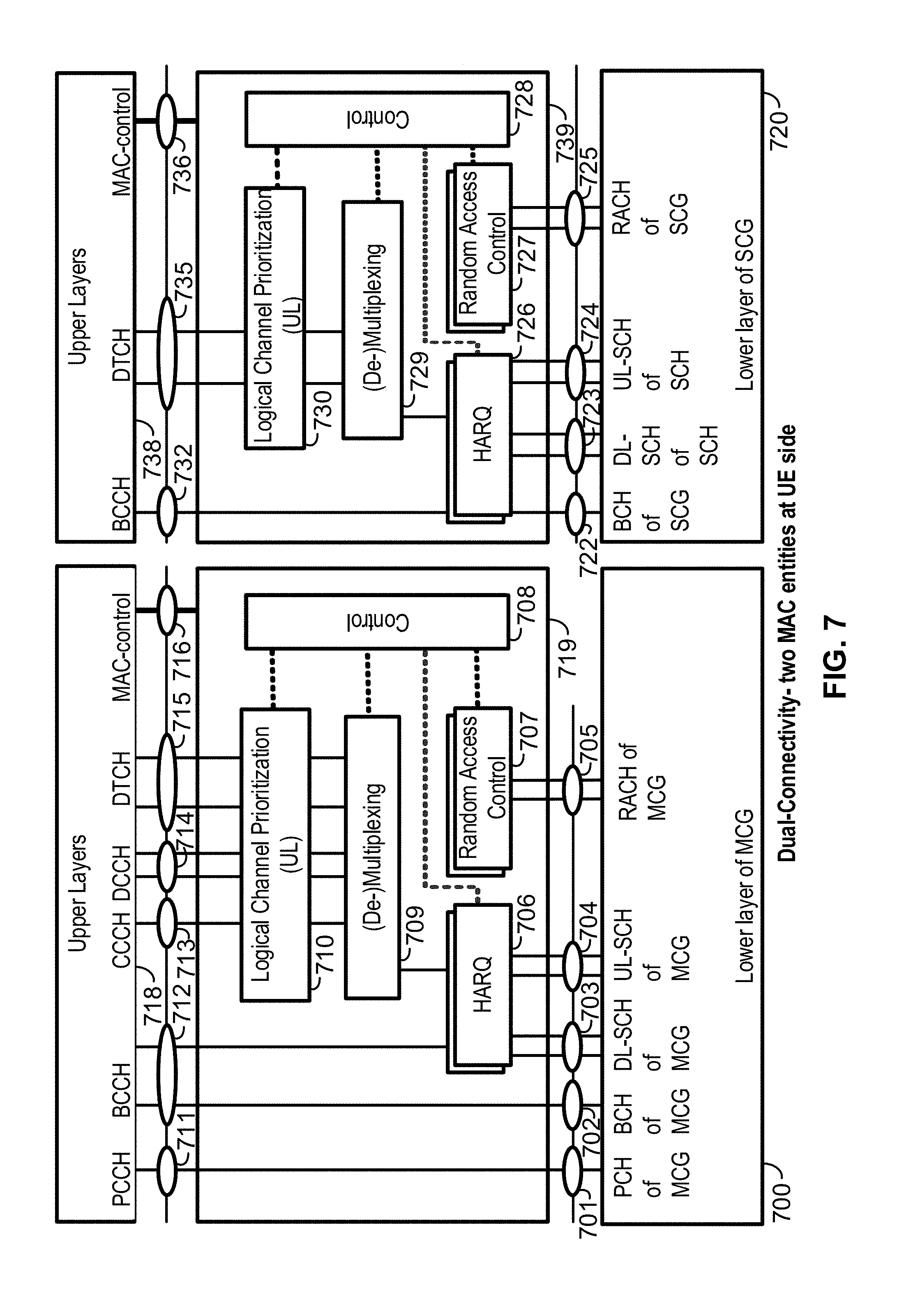
[0185] FIG. 7 shows an example structure for the UE side MAC entities, e.g., if a Master Cell Group (MCG) and a Secondary Cell Group (SCG) are configured. Media Broadcast Multicast Service (MBMS) reception may be included but is not shown in this figure for simplicity.
[0186] In multi-connectivity, the radio protocol architecture that a particular bearer uses may depend on how the bearer is set up. As an example, three alternatives may exist, an MCG bearer, an SCG bearer, and a split bearer, such as shown in FIG. 6. NR RRC may be located in a master gNB and SRBs may be configured as a MCG bearer type and may use the radio resources of the master gNB. Multi-connectivity may have at least one bearer configured to use radio resources provided by the secondary gNB. Multi-connectivity may or may not be configured or implemented.
[0187] For multi-connectivity, the wireless device may be configured with multiple NR MAC entities: e.g., one NR MAC entity for a master gNB, and other NR MAC entities for secondary gNBs. In multi-connectivity, the configured set of serving cells for a wireless device may comprise two subsets: e.g., the Master Cell Group (MCG) including the serving cells of the master gNB, and the Secondary Cell Groups (SCGs) including the serving cells of the secondary gNBs.
[0188] At least one cell in a SCG may have a configured UL component carrier (CC) and one of the UL CCs, e.g., named PSCell (or PCell of SCG, or sometimes called PCell), may be configured with PUCCH resources. If the SCG is configured, there may be at least one SCG bearer or one split bearer. If a physical layer problem or a random access problem on a PSCell occurs or is detected, if the maximum number of NR RLC retransmissions has been reached associated with the SCG, or if an access problem on a PSCell during a SCG addition or a SCG change occurs or is detected, then an RRC connection re-establishment procedure may not be triggered, UL transmissions towards cells of the SCG may be stopped, a master gNB may be informed by the wireless device of a SCG failure type, and for a split bearer the DL data transfer over the master gNB may be maintained. The NR RLC Acknowledge Mode (AM) bearer may be configured for the split bearer. Like the PCell, a PSCell may not be de-activated. The PSCell may be changed with an SCG change (e.g., with a security key change and a RACH procedure). A direct bearer type may change between a split bearer and an SCG bearer, or a simultaneous configuration of an SCG and a split bearer may or may not be supported.
[0189] A master gNB and secondary gNBs may interact for multi-connectivity. The master gNB may maintain the RRM measurement configuration of the wireless device, and the master gNB may, (e.g., based on received measurement reports, and/or based on traffic conditions and/or bearer types), decide to ask a secondary gNB to provide additional resources (e.g., serving cells) for a wireless device. If a request from the master gNB is received, a secondary gNB may create a container that may result in the configuration of additional serving cells for the wireless device (or the secondary gNB decide that it has no resource available to do so). For wireless device capability coordination, the master gNB may provide some or all of the Active Set (AS) configuration and the wireless device capabilities to the secondary gNB. The master gNB and the secondary gNB may exchange information about a wireless device configuration, such as by employing NR RRC containers (e.g., inter-node messages) carried in Xn messages. The secondary gNB may initiate a reconfiguration of its existing serving cells (e.g., PUCCH towards the secondary gNB). The secondary gNB may decide which cell is the PSCell within the SCG. The master gNB may or may not change the content of the NR RRC configuration provided by the secondary gNB. In an SCG addition and an SCG SCell addition, the master gNB may provide the latest measurement results for the SCG cell(s). Both a master gNB and a secondary gNBs may know the system frame number (SFN) and subframe offset of each other by operations, administration, and maintenance (OAM) (e.g., for the purpose of discontinuous reception (DRX) alignment and identification of a measurement gap). If adding a new SCG SCell, dedicated NR RRC signaling may be used for sending required system information of the cell for CA, except, e.g., for the SFN acquired from an MIB of the PSCell of an SCG.
[0190] FIG. 7 shows an example of dual-connectivity (DC) for two MAC entities at a wireless device side. A first MAC entity may comprise a lower layer of an MCG 700, an upper layer of an MCG 718, and one or more intermediate layers of an MCG 719. The lower layer of the MCG 700 may comprise, e.g., a paging channel (PCH) 701, a broadcast channel (BCH) 702, a downlink shared channel (DL-SCH) 703, an uplink shared channel (UL-SCH) 704, and a random access channel (RACH) 705. The one or more intermediate layers of the MCG 719 may comprise, e.g., one or more hybrid automatic repeat request (HARQ) processes 706, one or more random access control processes 707, multiplexing and/or de-multiplexing processes 709, logical channel prioritization on the uplink processes 710, and a control processes 708 providing control for the above processes in the one or more intermediate layers of the MCG 719. The upper layer of the MCG 718 may comprise, e.g., a paging control channel (PCCH) 711, a broadcast control channel (BCCH) 712, a common control channel (CCCH) 713, a dedicated control channel (DCCH) 714, a dedicated traffic channel (DTCH) 715, and a MAC control 716.
[0191] A second MAC entity may comprise a lower layer of an SCG 720, an upper layer of an SCG 738, and one or more intermediate layers of an SCG 739. The lower layer of the SCG 720 may comprise, e.g., a BCH 722, a DL-SCH 723, an UL-SCH 724, and a RACH 725. The one or more intermediate layers of the SCG 739 may comprise, e.g., one or more HARQ processes 726, one or more random access control processes 727, multiplexing and/or de-multiplexing processes 729, logical channel prioritization on the uplink processes 730, and a control processes 728 providing control for the above processes in the one or more intermediate layers of the SCG 739. The upper layer of the SCG 738 may comprise, e.g., a BCCH 732, a DCCH 714, a DTCH 735, and a MAC control 736.
[0192] Serving cells may be grouped in a TA group (TAG). Serving cells in one TAG may use the same timing reference. For a given TAG, a wireless device may use at least one downlink carrier as a timing reference. For a given TAG, a wireless device may synchronize uplink subframe and frame transmission timing of uplink carriers belonging to the same TAG. Serving cells having an uplink to which the same TA applies may correspond to serving cells hosted by the same receiver. A wireless device supporting multiple TAs may support two or more TA groups. One TA group may include the PCell and may be called a primary TAG (pTAG). In a multiple TAG configuration, at least one TA group may not include the PCell and may be called a secondary TAG (sTAG). Carriers within the same TA group may use the same TA value and/or the same timing reference. If DC is configured, cells belonging to a cell group (e.g., MCG or SCG) may be grouped into multiple TAGs including a pTAG and one or more sTAGs.
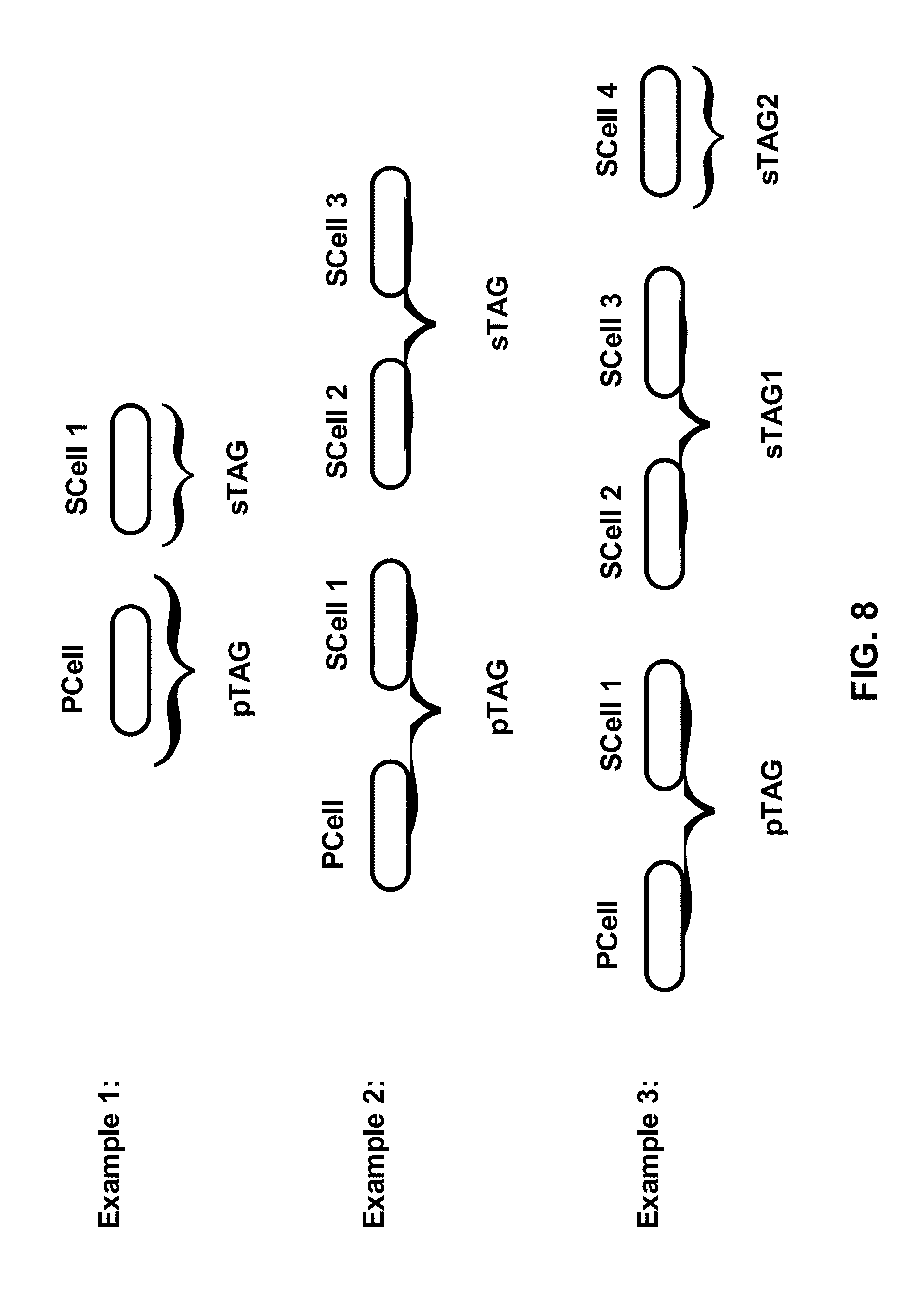
[0193] FIG. 8 shows example TAG configurations. In Example 1, a pTAG comprises a PCell, and an sTAG comprises an SCell1. In Example 2, a pTAG comprises a PCell and an SCell1, and an sTAG comprises an SCell2 and an SCell3. In Example 3, a pTAG comprises a PCell and an SCell1, and an sTAG1 comprises an SCell2 and an SCell3, and an sTAG2 comprises a SCell4. Up to four TAGs may be supported in a cell group (MCG or SCG), and other example TAG configurations may also be provided. In various examples, structures and operations are described for use with a pTAG and an sTAG. Some of the examples may be used for configurations with multiple sTAGs.
[0194] An eNB may initiate an RA procedure, via a PDCCH order, for an activated SCell. The PDCCH order may be sent on a scheduling cell of this SCell. If cross carrier scheduling is configured for a cell, the scheduling cell may be different than the cell that is employed for preamble transmission, and the PDCCH order may include an SCell index. At least a non-contention based RA procedure may be supported for SCell(s) assigned to sTAG(s).
[0195] FIG. 9 shows an example of random access processes, and a corresponding message flow, in a secondary TAG. A base station, such as an eNB, may transmit an activation command 900 to a wireless device, such as a UE. The activation command 900 may be transmitted to activate an SCell. The base station may also transmit a PDDCH order 901 to the wireless device, which may be transmitted, e.g., after the activation command 900. The wireless device may begin to perform a RACH process for the SCell, which may be initiated, e.g., after receiving the PDDCH order 901. A wireless device may transmit to the base station (e.g., as part of a RACH process) a preamble 902 (e.g., Msg1), such as a random access preamble (RAP). The preamble 902 may be transmitted in response to the PDCCH order 901. The wireless device may transmit the preamble 902 via an SCell belonging to an sTAG. Preamble transmission for SCells may be controlled by a network using PDCCH format 1A. The base station may send a random access response (RAR) 903 (e.g., Msg2 message) to the wireless device. The RAR 903 may be in response to the preamble 902 transmission via the SCell. The RAR 903 may be addressed to a random access radio network temporary identifier (RA-RNTI) in a PCell common search space (CSS). If the wireless device receives the RAR 903, the RACH process may conclude. The RACH process may conclude, e.g., after or in response to the wireless device receiving the RAR 903 from the base station. After the RACH process, the wireless device may transmit an uplink transmission 904. The uplink transmission 904 may comprise uplink packets transmitted via the same SCell used for the preamble 902 transmission.
[0196] Initial timing alignment for communications between the wireless device and the base station may be performed through a random access procedure, such as described above regarding FIG. 9. The random access procedure may involve a wireless device, such as a UE, transmitting a random access preamble and a base station, such as an eNB, responding with an initial TA command NTA (amount of timing advance) within a random access response window. The start of the random access preamble may be aligned with the start of a corresponding uplink subframe at the wireless device assuming NTA=0. The eNB may estimate the uplink timing from the random access preamble transmitted by the wireless device. The TA command may be derived by the eNB based on the estimation of the difference between the desired UL timing and the actual UL timing. The wireless device may determine the initial uplink transmission timing relative to the corresponding downlink of the sTAG on which the preamble is transmitted.
[0197] The mapping of a serving cell to a TAG may be configured by a serving eNB with RRC signaling. The mechanism for TAG configuration and reconfiguration may be based on RRC signaling. If an eNB performs an SCell addition configuration, the related TAG configuration may be configured for the SCell. An eNB may modify the TAG configuration of an SCell by removing (e.g., releasing) the SCell and adding (e.g., configuring) a new SCell (with the same physical cell ID and frequency) with an updated TAG ID. The new SCell with the updated TAG ID may initially be inactive subsequent to being assigned the updated TAG ID. The eNB may activate the updated new SCell and start scheduling packets on the activated SCell. In some examples, it may not be possible to change the TAG associated with an SCell, but rather, the SCell may need to be removed and a new SCell may need to be added with another TAG. For example, if there is a need to move an SCell from an sTAG to a pTAG, at least one RRC message, such as at least one RRC reconfiguration message, may be sent to the wireless device. The at least one RRC message may be sent to the wireless device to reconfigure TAG configurations, e.g., by releasing the SCell and configuring the SCell as a part of the pTAG. If, e.g., an SCell is added or configured without a TAG index, the SCell may be explicitly assigned to the pTAG. The PCell may not change its TA group and may be a member of the pTAG.
[0198] In LTE Release-10 and Release-11 CA, a PUCCH transmission is only transmitted on a PCell (e.g., a PSCell) to an eNB. In LTE-Release 12 and earlier, a wireless device may transmit PUCCH information on one cell (e.g., a PCell or a PSCell) to a given eNB. As the number of CA capable wireless devices increase, and as the number of aggregated carriers increase, the number of PUCCHs and the PUCCH payload size may increase. Accommodating the PUCCH transmissions on the PCell may lead to a high PUCCH load on the PCell. A PUCCH on an SCell may be used to offload the PUCCH resource from the PCell. More than one PUCCH may be configured. For example, a PUCCH on a PCell may be configured and another PUCCH on an SCell may be configured. One, two, or more cells may be configured with PUCCH resources for transmitting CSI, acknowledgment (ACK), and/or non-acknowledgment (NACK) to a base station. Cells may be grouped into multiple PUCCH groups, and one or more cell within a group may be configured with a PUCCH. In some examples, one SCell may belong to one PUCCH group. SCells with a configured PUCCH transmitted to a base station may be called a PUCCH SCell, and a cell group with a common PUCCH resource transmitted to the same base station may be called a PUCCH group.
[0199] A MAC entity may have a configurable timer, e.g., timeAlignmentTimer, per TAG. The timeAlignmentTimer may be used to control how long the MAC entity considers the serving cells belonging to the associated TAG to be uplink time aligned. If a Timing Advance Command MAC control element is received, the MAC entity may apply the Timing Advance Command for the indicated TAG; and/or the MAC entity may start or restart the timeAlignmentTimer associated with a TAG that may be indicated by the Timing Advance Command MAC control element. If a Timing Advance Command is received in a Random Access Response message for a serving cell belonging to a TAG, the MAC entity may apply the Timing Advance Command for this TAG and/or start or restart the timeAlignmentTimer associated with this TAG. Additionally or alternatively, if the Random Access Preamble is not selected by the MAC entity, the MAC entity may apply the Timing Advance Command for this TAG and/or start or restart the timeAlignmentTimer associated with this TAG. If the timeAlignmentTimer associated with this TAG is not running, the Timing Advance Command for this TAG may be applied, and the timeAlignmentTimer associated with this TAG may be started. If the contention resolution is not successful, a timeAlignmentTimer associated with this TAG may be stopped. If the contention resolution is successful, the MAC entity may ignore the received Timing Advance Command. The MAC entity may determine whether the contention resolution is successful or whether the contention resolution is not successful.
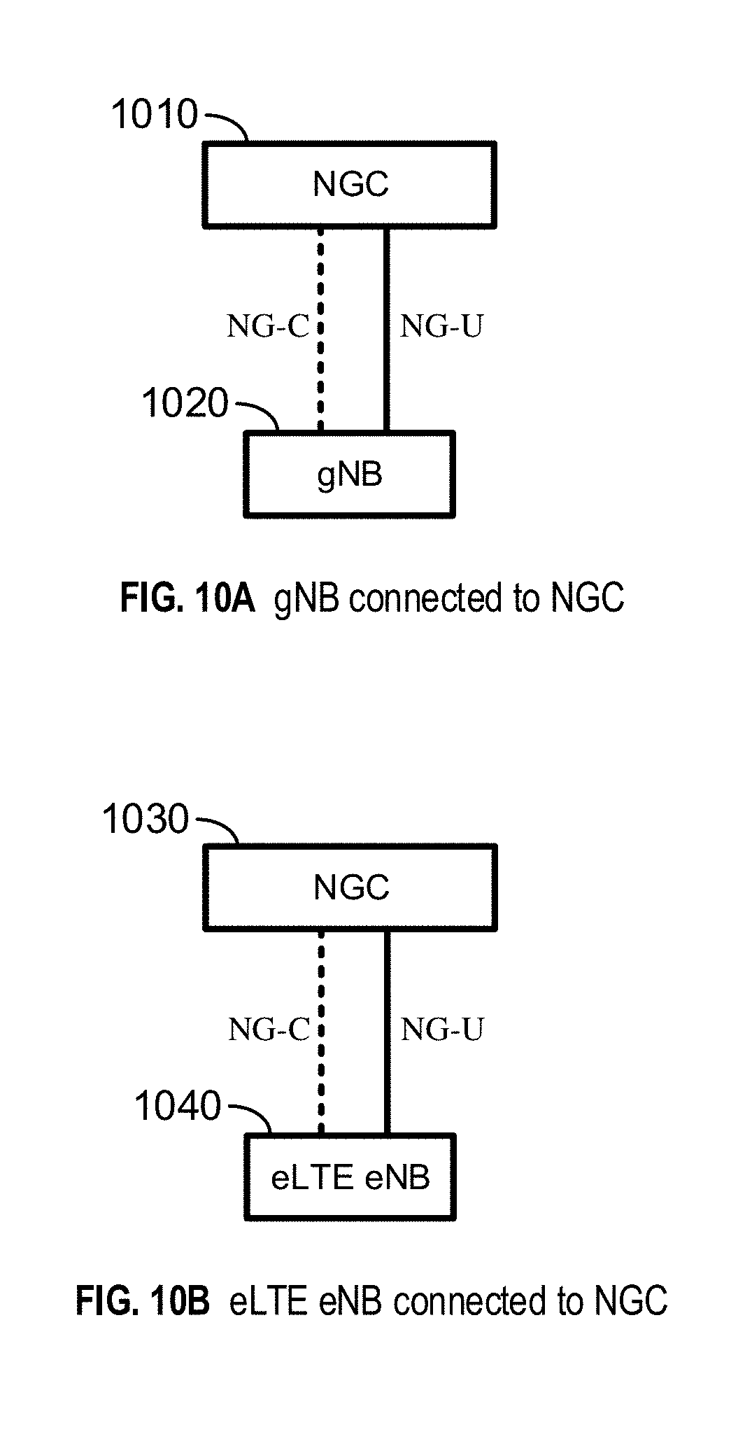
[0200] FIG. 10A and FIG. 10B show examples for interfaces between a 5G core network (e.g., NGC) and base stations (e.g., gNB and eLTE eNB). A base station, such as a gNB 1020, may be interconnected to an NGC 1010 control plane employing an NG-C interface. The base station, e.g., the gNB 1020, may also be interconnected to an NGC 1010 user plane (e.g., UPGW) employing an NG-U interface. As another example, a base station, such as an eLTE eNB 1040, may be interconnected to an NGC 1030 control plane employing an NG-C interface. The base station, e.g., the eLTE eNB 1040, may also be interconnected to an NGC 1030 user plane (e.g., UPGW) employing an NG-U interface. An NG interface may support a many-to-many relation between 5G core networks and base stations.
[0201] FIG. 11A, FIG. 11B, FIG. 11C, FIG. 11D, FIG. 11E, and FIG. 11F are examples for architectures of tight interworking between a 5G RAN and an LTE RAN. The tight interworking may enable a multiple receiver/transmitter (RX/TX) wireless device in an RRC_CONNECTED state to be configured to utilize radio resources provided by two schedulers located in two base stations (e.g., an eLTE eNB and a gNB). The two base stations may be connected via a non-ideal or ideal backhaul over the Xx interface between an LTE eNB and a gNB, or over the Xn interface between an eLTE eNB and a gNB. Base stations involved in tight interworking for a certain wireless device may assume different roles. For example, a base station may act as a master base station or a base station may act as a secondary base station. In tight interworking, a wireless device may be connected to both a master base station and a secondary base station. Mechanisms implemented in tight interworking may be extended to cover more than two base stations.
[0202] A master base station may be an LTE eNB 1102A or an LTE eNB 1102B, which may be connected to EPC nodes 1101A or 1101B, respectively. This connection to EPC nodes may be, e.g., to an MME via the S1-C interface and/or to an S-GW via the S1-U interface. A secondary base station may be a gNB 1103A or a gNB 1103B, either or both of which may be a non-standalone node having a control plane connection via an Xx-C interface to an LTE eNB (e.g., the LTE eNB 1102A or the LTE eNB 1102B). In the tight interworking architecture of FIG. 11A, a user plane for a gNB (e.g., the gNB 1103A) may be connected to an S-GW (e.g., the EPC 1101A) through an LTE eNB (e.g., the LTE eNB 1102A), via an Xx-U interface between the LTE eNB and the gNB, and via an S1-U interface between the LTE eNB and the S-GW. In the architecture of FIG. 11B, a user plane for a gNB (e.g., the gNB 1103B) may be connected directly to an S-GW (e.g., the EPC 1101B) via an S1-U interface between the gNB and the S-GW.
[0203] A master base station may be a gNB 1103C or a gNB 1103D, which may be connected to NGC nodes 1101C or 1101D, respectively. This connection to NGC nodes may be, e.g., to a control plane core node via the NG-C interface and/or to a user plane core node via the NG-U interface. A secondary base station may be an eLTE eNB 1102C or an eLTE eNB 1102D, either or both of which may be a non-standalone node having a control plane connection via an Xn-C interface to a gNB (e.g., the gNB 1103C or the gNB 1103D). In the tight interworking architecture of FIG. 11C, a user plane for an eLTE eNB (e.g., the eLTE eNB 1102C) may be connected to a user plane core node (e.g., the NGC 1101C) through a gNB (e.g., the gNB 1103C), via an Xn-U interface between the eLTE eNB and the gNB, and via an NG-U interface between the gNB and the user plane core node. In the architecture of FIG. 11D, a user plane for an eLTE eNB (e.g., the eLTE eNB 1102D) may be connected directly to a user plane core node (e.g., the NGC 1101D) via an NG-U interface between the eLTE eNB and the user plane core node.
[0204] A master base station may be an eLTE eNB 1102E or an eLTE eNB 1102F, which may be connected to NGC nodes 1101E or 1101F, respectively. This connection to NGC nodes may be, e.g., to a control plane core node via the NG-C interface and/or to a user plane core node via the NG-U interface. A secondary base station may be a gNB 1103E or a gNB 1103F, either or both of which may be a non-standalone node having a control plane connection via an Xn-C interface to an eLTE eNB (e.g., the eLTE eNB 1102E or the eLTE eNB 1102F). In the tight interworking architecture of FIG. 11E, a user plane for a gNB (e.g., the gNB 1103E) may be connected to a user plane core node (e.g., the NGC 1101E) through an eLTE eNB (e.g., the eLTE eNB 1102E), via an Xn-U interface between the eLTE eNB and the gNB, and via an NG-U interface between the eLTE eNB and the user plane core node. In the architecture of FIG. 11F, a user plane for a gNB (e.g., the gNB 1103F) may be connected directly to a user plane core node (e.g., the NGC 1101F) via an NG-U interface between the gNB and the user plane core node.
[0205] FIG. 12A, FIG. 12B, and FIG. 12C are examples for radio protocol structures of tight interworking bearers.
[0206] An LTE eNB 1201A may be an S1 master base station, and a gNB 1210A may be an S1 secondary base station. An example for a radio protocol architecture for a split bearer and an SCG bearer is shown. The LTE eNB 1201A may be connected to an EPC with a non-standalone gNB 1210A, via an Xx interface between the PDCP 1206A and an NR RLC 1212A. The LTE eNB 1201A may include protocol layers MAC 1202A, RLC 1203A and RLC 1204A, and PDCP 1205A and PDCP 1206A. An MCG bearer type may interface with the PDCP 1205A, and a split bearer type may interface with the PDCP 1206A. The gNB 1210A may include protocol layers NR MAC 1211A, NR RLC 1212A and NR RLC 1213A, and NR PDCP 1214A. An SCG bearer type may interface with the NR PDCP 1214A.
[0207] A gNB 1201B may be an NG master base station, and an eLTE eNB 1210B may be an NG secondary base station. An example for a radio protocol architecture for a split bearer and an SCG bearer is shown. The gNB 1201B may be connected to an NGC with a non-standalone eLTE eNB 1210B, via an Xn interface between the NR PDCP 1206B and an RLC 1212B. The gNB 1201B may include protocol layers NR MAC 1202B, NR RLC 1203B and NR RLC 1204B, and NR PDCP 1205B and NR PDCP 1206B. An MCG bearer type may interface with the NR PDCP 1205B, and a split bearer type may interface with the NR PDCP 1206B. The eLTE eNB 1210B may include protocol layers MAC 1211B, RLC 1212B and RLC 1213B, and PDCP 1214B. An SCG bearer type may interface with the PDCP 1214B.
[0208] An eLTE eNB 1201C may be an NG master base station, and a gNB 1210C may be an NG secondary base station. An example for a radio protocol architecture for a split bearer and an SCG bearer is shown. The eLTE eNB 1201C may be connected to an NGC with a non-standalone gNB 1210C, via an Xn interface between the PDCP 1206C and an NR RLC 1212C. The eLTE eNB 1201C may include protocol layers MAC 1202C, RLC 1203C and RLC 1204C, and PDCP 1205C and PDCP 1206C. An MCG bearer type may interface with the PDCP 1205C, and a split bearer type may interface with the PDCP 1206C. The gNB 1210C may include protocol layers NR MAC 1211C, NR RLC 1212C and NR RLC 1213C, and NR PDCP 1214C. An SCG bearer type may interface with the NR PDCP 1214C.
[0209] In a 5G network, the radio protocol architecture that a particular bearer uses may depend on how the bearer is setup. At least three alternatives may exist, e.g., an MCG bearer, an SCG bearer, and a split bearer, such as shown in FIG. 12A, FIG. 12B, and FIG. 12C. The NR RRC may be located in a master base station, and the SRBs may be configured as an MCG bearer type and may use the radio resources of the master base station. Tight interworking may have at least one bearer configured to use radio resources provided by the secondary base station. Tight interworking may or may not be configured or implemented.
[0210] The wireless device may be configured with two MAC entities: e.g., one MAC entity for a master base station, and one MAC entity for a secondary base station. In tight interworking, the configured set of serving cells for a wireless device may comprise of two subsets: e.g., the Master Cell Group (MCG) including the serving cells of the master base station, and the Secondary Cell Group (SCG) including the serving cells of the secondary base station.
[0211] At least one cell in a SCG may have a configured UL CC and one of them, e.g., a PSCell (or the PCell of the SCG, which may also be called a PCell), is configured with PUCCH resources. If the SCG is configured, there may be at least one SCG bearer or one split bearer. If one or more of a physical layer problem or a random access problem is detected on a PSCell, if the maximum number of (NR) RLC retransmissions associated with the SCG has been reached, and/or if an access problem on a PSCell during an SCG addition or during an SCG change is detected, then: an RRC connection re-establishment procedure may not be triggered, UL transmissions towards cells of the SCG may be stopped, a master base station may be informed by the wireless device of a SCG failure type, and/or for a split bearer the DL data transfer over the master base station may be maintained. The RLC AM bearer may be configured for the split bearer. Like the PCell, a PSCell may not be de-activated. A PSCell may be changed with an SCG change, e.g., with security key change and a RACH procedure. A direct bearer type change, between a split bearer and an SCG bearer, may not be supported. Simultaneous configuration of an SCG and a split bearer may not be supported.
[0212] A master base station and a secondary base station may interact. The master base station may maintain the RRM measurement configuration of the wireless device. The master base station may determine to ask a secondary base station to provide additional resources (e.g., serving cells) for a wireless device. This determination may be based on, e.g., received measurement reports, traffic conditions, and/or bearer types. If a request from the master base station is received, a secondary base station may create a container that may result in the configuration of additional serving cells for the wireless device, or the secondary base station may determine that it has no resource available to do so. The master base station may provide at least part of the AS configuration and the wireless device capabilities to the secondary base station, e.g., for wireless device capability coordination. The master base station and the secondary base station may exchange information about a wireless device configuration such as by using RRC containers (e.g., inter-node messages) carried in Xn or Xx messages. The secondary base station may initiate a reconfiguration of its existing serving cells (e.g., PUCCH towards the secondary base station). The secondary base station may determine which cell is the PSCell within the SCG. The master base station may not change the content of the RRC configuration provided by the secondary base station. If an SCG is added and/or an SCG SCell is added, the master base station may provide the latest measurement results for the SCG cell(s). Either or both of a master base station and a secondary base station may know the SFN and subframe offset of each other by OAM, (e.g., for the purpose of DRX alignment and identification of a measurement gap). If a new SCG SCell is added, dedicated RRC signaling may be used for sending required system information of the cell, such as for CA, except, e.g., for the SFN acquired from an MIB of the PSCell of an SCG.
[0213] FIG. 13A and FIG. 13B show examples for gNB deployment. A core 1301 and a core 1310 may interface with other nodes via RAN-CN interfaces. In a non-centralized deployment example, the full protocol stack (e.g., NR RRC, NR PDCP, NR RLC, NR MAC, and NR PHY) may be supported at one node, such as a gNB 1302, a gNB 1303, and/or an eLTE eNB or LTE eNB 1304. These nodes (e.g., the gNB 1302, the gNB 1303, and the eLTE eNB or LTE eNB 1304) may interface with one of more of each other via a respective inter-BS interface. In a centralized deployment example, upper layers of a gNB may be located in a Central Unit (CU) 1311, and lower layers of the gNB may be located in Distributed Units (DU) 1312, 1313, and 1314. The CU-DU interface (e.g., Fs interface) connecting CU 1311 and DUs 1312, 1312, and 1314 may be ideal or non-ideal. The Fs-C may provide a control plane connection over the Fs interface, and the Fs-U may provide a user plane connection over the Fs interface. In the centralized deployment, different functional split options between the CU 1311 and the DUs 1312, 1313, and 1314 may be possible by locating different protocol layers (e.g., RAN functions) in the CU 1311 and in the DU 1312, 1313, and 1314. The functional split may support flexibility to move the RAN functions between the CU 1311 and the DUs 1312, 1313, and 1314 depending on service requirements and/or network environments. The functional split option may change during operation (e.g., after the Fs interface setup procedure), or the functional split option may change only in the Fs setup procedure (e.g., the functional split option may be static during operation after Fs setup procedure).
[0214] FIG. 14 shows examples for different functional split options of a centralized gNB deployment. Element numerals that are followed by "A" or "B" designations in FIG. 14 may represent the same elements in different traffic flows, e.g., either receiving data (e.g., data 1402A) or sending data (e.g., 1402B). In the split option example 1, an NR RRC 1401 may be in a CU, and an NR PDCP 1403, an NR RLC (e.g., comprising a High NR RLC 1404 and/or a Low NR RLC 1405), an NR MAC (e.g., comprising a High NR MAC 1406 and/or a Low NR MAC 1407), an NR PHY (e.g., comprising a High NR PHY 1408 and/or a LOW NR PHY 1409), and an RF 1410 may be in a DU. In the split option example 2, the NR RRC 1401 and the NR PDCP 1403 may be in a CU, and the NR RLC, the NR MAC, the NR PHY, and the RF 1410 may be in a DU. In the split option example 3, the NR RRC 1401, the NR PDCP 1403, and a partial function of the NR RLC (e.g., the High NR RLC 1404) may be in a CU, and the other partial function of the NR RLC (e.g., the Low NR RLC 1405), the NR MAC, the NR PHY, and the RF 1410 may be in a DU. In the split option example 4, the NR RRC 1401, the NR PDCP 1403, and the NR RLC may be in a CU, and the NR MAC, the NR PHY, and the RF 1410 may be in a DU. In the split option example 5, the NR RRC 1401, the NR PDCP 1403, the NR RLC, and a partial function of the NR MAC (e.g., the High NR MAC 1406) may be in a CU, and the other partial function of the NR MAC (e.g., the Low NR MAC 1407), the NR PHY, and the RF 1410 may be in a DU. In the split option example 6, the NR RRC 1401, the NR PDCP 1403, the NR RLC, and the NR MAC may be in CU, and the NR PHY and the RF 1410 may be in a DU. In the split option example 7, the NR RRC 1401, the NR PDCP 1403, the NR RLC, the NR MAC, and a partial function of the NR PHY (e.g., the High NR PHY 1408) may be in a CU, and the other partial function of the NR PHY (e.g., the Low NR PHY 1409) and the RF 1410 may be in a DU. In the split option example 8, the NR RRC 1401, the NR PDCP 1403, the NR RLC, the NR MAC, and the NR PHY may be in a CU, and the RF 1410 may be in a DU.
[0215] The functional split may be configured per CU, per DU, per wireless device, per bearer, per slice, and/or with other granularities. In a per CU split, a CU may have a fixed split, and DUs may be configured to match the split option of the CU. In a per DU split, each DU may be configured with a different split, and a CU may provide different split options for different DUs. In a per wireless device split, a gNB (e.g., a CU and a DU) may provide different split options for different wireless devices. In a per bearer split, different split options may be utilized for different bearer types. In a per slice splice, different split options may be applied for different slices.
[0216] A new radio access network (new RAN) may support different network slices, which may allow differentiated treatment customized to support different service requirements with end to end scope. The new RAN may provide a differentiated handling of traffic for different network slices that may be pre-configured, and the new RAN may allow a single RAN node to support multiple slices. The new RAN may support selection of a RAN part for a given network slice, e.g., by one or more slice ID(s) or NSSAI(s) provided by a wireless device or provided by an NGC (e.g., an NG CP). The slice ID(s) or NSSAI(s) may identify one or more of pre-configured network slices in a PLMN. For an initial attach, a wireless device may provide a slice ID and/or an NSSAI, and a RAN node (e.g., a gNB) may use the slice ID or the NSSAI for routing an initial NAS signaling to an NGC control plane function (e.g., an NG CP). If a wireless device does not provide any slice ID or NSSAI, a RAN node may send a NAS signaling to a default NGC control plane function. For subsequent accesses, the wireless device may provide a temporary ID for a slice identification, which may be assigned by the NGC control plane function, to enable a RAN node to route the NAS message to a relevant NGC control plane function. The new RAN may support resource isolation between slices. If the RAN resource isolation is implemented, shortage of shared resources in one slice does not cause a break in a service level agreement for another slice.
[0217] The amount of data traffic carried over networks is expected to increase for many years to come. The number of users and/or devices is increasing and each user/device accesses an increasing number and variety of services, e.g., video delivery, large files, and images. This requires not only high capacity in the network, but also provisioning very high data rates to meet customers' expectations on interactivity and responsiveness. More spectrum may be required for network operators to meet the increasing demand. Considering user expectations of high data rates along with seamless mobility, it is beneficial that more spectrum be made available for deploying macro cells as well as small cells for communication systems.
[0218] Striving to meet the market demands, there has been increasing interest from operators in deploying some complementary access utilizing unlicensed spectrum to meet the traffic growth. This is exemplified by the large number of operator-deployed Wi-Fi networks and the 3GPP standardization of LTE/WLAN interworking solutions. This interest indicates that unlicensed spectrum, if present, may be an effective complement to licensed spectrum for network operators, e.g., to help address the traffic explosion in some examples, such as hotspot areas. Licensed Assisted Access (LAA) offers an alternative for operators to make use of unlicensed spectrum, e.g., if managing one radio network, offering new possibilities for optimizing the network's efficiency.
[0219] Listen-before-talk (clear channel assessment) may be implemented for transmission in an LAA cell. In a listen-before-talk (LBT) procedure, equipment may apply a clear channel assessment (CCA) check before using the channel. For example, the CCA may utilize at least energy detection to determine the presence or absence of other signals on a channel to determine if a channel is occupied or clear, respectively. For example, European and Japanese regulations mandate the usage of LBT in the unlicensed bands. Apart from regulatory requirements, carrier sensing via LBT may be one way for fair sharing of the unlicensed spectrum.
[0220] Discontinuous transmission on an unlicensed carrier with limited maximum transmission duration may be enabled. Some of these functions may be supported by one or more signals to be transmitted from the beginning of a discontinuous LAA downlink transmission. Channel reservation may be enabled by the transmission of signals, by an LAA node, after gaining channel access, e.g., via a successful LBT operation, so that other nodes that receive the transmitted signal with energy above a certain threshold sense the channel to be occupied. Functions that may need to be supported by one or more signals for LAA operation with discontinuous downlink transmission may include one or more of the following: detection of the LAA downlink transmission (including cell identification) by wireless devices, time synchronization of wireless devices, and frequency synchronization of wireless devices.
[0221] DL LAA design may employ subframe boundary alignment according to LTE-A carrier aggregation timing relationships across serving cells aggregated by CA. This may not indicate that the eNB transmissions may start only at the subframe boundary. LAA may support transmitting PDSCH if not all OFDM symbols are available for transmission in a subframe according to LBT. Delivery of necessary control information for the PDSCH may also be supported.
[0222] LBT procedures may be employed for fair and friendly coexistence of LAA with other operators and technologies operating in unlicensed spectrum. LBT procedures on a node attempting to transmit on a carrier in unlicensed spectrum may require the node to perform a clear channel assessment to determine if the channel is free for use. An LBT procedure may involve at least energy detection to determine if the channel is being used. For example, regulatory requirements in some regions, e.g., in Europe, specify an energy detection threshold such that if a node receives energy greater than this threshold, the node assumes that the channel is not free. Nodes may follow such regulatory requirements. A node may optionally use a lower threshold for energy detection than that specified by regulatory requirements. LAA may employ a mechanism to adaptively change the energy detection threshold, e.g., LAA may employ a mechanism to adaptively lower the energy detection threshold from an upper bound. Adaptation mechanism may not preclude static or semi-static setting of the threshold. A Category 4 LBT mechanism or other type of LBT mechanisms may be implemented.
[0223] Various example LBT mechanisms may be implemented. For some signals, in some implementation scenarios, in some situations, and/or in some frequencies, no LBT procedure may performed by the transmitting entity. For example, Category 2 (e.g., LBT without random back-off) may be implemented. The duration of time that the channel is sensed to be idle before the transmitting entity transmits may be deterministic. For example, Category 3 (e.g., LBT with random back-off with a contention window of fixed size) may be implemented. The LBT procedure may have the following procedure as one of its components. The transmitting entity may draw a random number N within a contention window. The size of the contention window may be specified by the minimum and maximum value of N. The size of the contention window may be fixed. The random number N may be employed in the LBT procedure to determine the duration of time that the channel is sensed to be idle, e.g., before the transmitting entity transmits on the channel. For example, Category 4 (e.g., LBT with random back-off with a contention window of variable size) may be implemented. The transmitting entity may draw a random number N within a contention window. The size of contention window may be specified by the minimum and maximum value of N. The transmitting entity may vary the size of the contention window if drawing the random number N. The random number N may be used in the LBT procedure to determine the duration of time that the channel is sensed to be idle, e.g., before the transmitting entity transmits on the channel.
[0224] LAA may employ uplink LBT at the wireless device. The UL LBT scheme may be different from the DL LBT scheme, e.g., by using different LBT mechanisms or parameters. These differences in schemes may be due to the LAA UL being based on scheduled access, which may affect a wireless device's channel contention opportunities. Other considerations motivating a different UL LBT scheme may include, but are not limited to, multiplexing of multiple wireless devices in a single subframe.
[0225] A DL transmission burst may be a continuous transmission from a DL transmitting node, e.g., with no transmission immediately before or after from the same node on the same CC. An UL transmission burst from a wireless device perspective may be a continuous transmission from a wireless device, e.g., with no transmission immediately before or after from the same wireless device on the same CC. A UL transmission burst may be defined from a wireless device perspective or from an eNB perspective. If an eNB is operating DL and UL LAA over the same unlicensed carrier, DL transmission burst(s) and UL transmission burst(s) on LAA may be scheduled in a TDM manner over the same unlicensed carrier. An instant in time may be part of a DL transmission burst or part of an UL transmission burst.
[0226] A base station may transmit a plurality of beams to a wireless device. A serving beam may be determined, from the plurality of beams, for the wireless communications between the base station and the wireless device. One or more candidate beams may also be determined, from the plurality of beams, for providing the wireless communications if a beam failure event occurs, e.g., such that the serving beam becomes unable to provide the desired communications. One or more candidate beams may be determined by a wireless device and/or by a base station. By determining and configuring a candidate beam, the wireless device and base station may continue wireless communications if the serving beam experiences a beam failure event.
[0227] Single beam and multi-beam operations may be supported, e.g., in a NR (New Radio) system. In a multi-beam example, a base station (e.g., a gNB in NR) may perform a downlink beam sweep to provide coverage for DL synchronization signals (SSs) and common control channels. Wireless devices may perform uplink beam sweeps for UL direction to access a cell. In a single beam example, a base station may configure time-repetition within one synchronization signal (SS) block. This time-repetition may comprise, e.g., one or more of a primary synchronization signal (PSS), a secondary synchronization signal (SSS), and a physical broadcast channel (PBCH). These signals may be in a wide beam. In a multi-beam examples, a base station may configure one or more of these signals and physical channels, such as an SS Block, in multiple beams. A wireless device may identify, e.g., from an SS block, an OFDM symbol index, a slot index in a radio frame, and a radio frame number.
[0228] In an RRC_INACTIVE state or in an RRC_IDLE state, a wireless device may assume that SS blocks form an SS burst and an SS burst set. An SS burst set may have a given periodicity. SS blocks may be transmitted together in multiple beams (e.g., in multiple beam examples) to form an SS burst. One or more SS blocks may be transmitted via one beam. A beam may have a steering direction. If multiple SS bursts transmit beams, these SS bursts together may form an SS burst set, such as shown in FIG. 15. A base station 1501 (e.g., a gNB in NR) may transmit SS bursts 1502A to 1502H during time periods 1503. A plurality of these SS bursts may comprise an SS burst set, such as an SS burst set 1504 (e.g., SS bursts 1502A and 1502E). An SS burst set may comprise any number of a plurality of SS bursts 1502A to 1502H. Each SS burst within an SS burst set may transmitted at a fixed or variable periodicity during time periods 1503.
[0229] In a multi-beam example, one or more of PSS, SSS, or PBCH signals may be repeated for a cell, e.g., to support cell selection, cell reselection, and/or initial access procedures. For an SS burst, an associated PBCH or a physical downlink shared channel (PDSCH) scheduling system information may be broadcasted by a base station to multiple wireless devices. The PDSCH may be indicated by a physical downlink control channel (PDCCH) in a common search space. The system information may comprise system information block type 2 (SIB2). SIB2 may carry a physical random access channel (PRACH) configuration for a beam. For a beam, a base station (e.g., a gNB in NR) may have a RACH configuration which may include a PRACH preamble pool, time and/or frequency radio resources, and other power related parameters. A wireless device may use a PRACH preamble from a RACH configuration to initiate a contention-based RACH procedure or a contention-free RACH procedure. A wireless device may perform a 4-step RACH procedure, which may be a contention-based RACH procedure or a contention-free RACH procedure. The wireless device may select a beam associated with an SS block that may have the best receiving signal quality. The wireless device may successfully detect a cell identifier that may be associated with the cell and decode system information with a RACH configuration. The wireless device may use one PRACH preamble and select one PRACH resource from RACH resources indicated by the system information associated with the selected beam. A PRACH resource may comprise at least one of: a PRACH index indicating a PRACH preamble, a PRACH format, a PRACH numerology, time and/or frequency radio resource allocation, power setting of a PRACH transmission, and/or other radio resource parameters. For a contention-free RACH procedure, the PRACH preamble and resource may be indicated in a DCI or other high layer signaling.
[0230] FIG. 16 shows an example of a random access procedure (e.g., via a RACH) that may include sending, by a base station, one or more SS blocks. A wireless device 1620 (e.g., a UE) may transmit one or more preambles to a base station 1621 (e.g., a gNB in NR). Each preamble transmission by the wireless device may be associated with a separate random access procedure, such as shown in FIG. 16. The random access procedure may begin at step 1601 with a base station 1621 (e.g., a gNB in NR) sending a first SS block to a wireless device 1621 (e.g., a UE). Any of the SS blocks may comprise one or more of a PSS, SSS, tertiary synchronization signal (TSS), or PBCH signal. The first SS block in step 1601 may be associated with a first PRACH configuration. At step 1602, the base station 1621 may send to the wireless device 1620 a second SS block that may be associated with a second PRACH configuration. At step 1603, the base station 1621 may send to the wireless device 1620 a third SS block that may be associated with a third PRACH configuration. At step 1604, the base station 1621 may send to the wireless device 1620 a fourth SS block that may be associated with a fourth PRACH configuration. Any number of SS blocks may be sent in the same manner in addition to, or replacing, steps 1603 and 1604. An SS burst may comprise any number of SS blocks. For example, SS burst 1610 comprises the three SS blocks sent during steps 1602-1604.
[0231] The wireless device 1620 may send to the base station 1621 a preamble, at step 1605, e.g., after or in response to receiving one or more SS blocks or SS bursts. The preamble may comprise a PRACH preamble, and may be referred to as RA Msg 1. The PRACH preamble may be transmitted in step 1605 according to or based on a PRACH configuration that may be received in an SS block (e.g., one of the SS blocks from steps 1601-1604) that may be determined to be the best SS block beam. The wireless device 1620 may determine a best SS block beam from among SS blocks it may receive prior to sending the PRACH preamble. The base station 1621 may send a random access response (RAR), which may be referred to as RA Msg2, at step 1606, e.g., after or in response to receiving the PRACH preamble. The RAR may be transmitted in step 1606 via a DL beam that corresponds to the SS block beam associated with the PRACH configuration. The base station 1621 may determine the best SS block beam from among SS blocks it previously sent prior to receiving the PRACH preamble. The base station 1621 may receive the PRACH preamble according to or based on the PRACH configuration associated with the best SS block beam.
[0232] The wireless device 1620 may send to the base station 1621 an RRCConnectionRequest and/or RRCConnectionResumeRequest message, which may be referred to as RA Msg3, at step 1607, e.g., after or in response to receiving the RAR. The base station 1621 may send to the wireless device 1620 an RRCConnectionSetup and/or RRCConnectionResume message, which may be referred to as RA Msg4, at step 1608, e.g., after or in response to receiving the RRCConnectionRequest and/or RRCConnectionResumeRequest message. The wireless device 1620 may send to the base station 1621 an RRCConnectionSetupComplete and/or RRCConnectionResumeComplete message, which may be referred to as RA Msg5, at step 1609, e.g., after or in response to receiving the RRCConnectionSetup and/or RRCConnectionResume. An RRC connection may be established between the wireless device 1620 and the base station 1621, and the random access procedure may end, e.g., after or in response to receiving the RRCConnectionSetupComplete and/or RRCConnectionResumeComplete message.
[0233] A best beam, including but not limited to a best SS block beam, may be determined based on a channel state information reference signal (CSI-RS). A wireless device may use a CSI-RS in a multi-beam system for estimating the beam quality of the links between the wireless device and a base station. For example, based on a measurement of a CSI-RS, a wireless device may report CSI for downlink channel adaption. A CSI parameter may include a precoding matrix index (PMI), a channel quality index (CQI) value, and/or a rank indicator (RI). A wireless device may report a beam index based on a reference signal received power (RSRP) measurement on a CSI-RS. The wireless device may report the beam index in a CSI resource indication (CRI) for downlink beam selection. A base station may transmit a CSI-RS via a CSI-RS resource, such as via one or more antenna ports, or via one or more time and/or frequency radio resources. A beam may be associated with a CSI-RS. A CSI-RS may comprise an indication of a beam direction. Each of a plurality of beams may be associated with one of a plurality of CSI-RSs. A CSI-RS resource may be configured in a cell-specific way, e.g., via common RRC signaling. Additionally or alternatively, a CSI-RS resource may be configured in a wireless device-specific way, e.g., via dedicated RRC signaling and/or layer 1 and/or layer 2 (L1/L2) signaling. Multiple wireless devices in or served by a cell may measure a cell-specific CSI-RS resource. A dedicated subset of wireless devices in or served by a cell may measure a wireless device-specific CSI-RS resource. A base station may transmit a CSI-RS resource periodically, using aperiodic transmission, or using a multi-shot or semi-persistent transmission. In a periodic transmission, a base station may transmit the configured CSI-RS resource using a configured periodicity in the time domain. In an aperiodic transmission, a base station may transmit the configured CSI-RS resource in a dedicated time slot. In a multi-shot or semi-persistent transmission, a base station may transmit the configured CSI-RS resource in a configured period. A base station may configure different CSI-RS resources in different terms for different purposes. Different terms may include, e.g., cell-specific, device-specific, periodic, aperiodic, multi-shot, or other terms. Different purposes may include, e.g., beam management, CQI reporting, or other purposes.
[0234] FIG. 17 shows an example of transmitting CSI-RSs periodically for a beam. A base station 1701 may transmit a beam in a predefined order in the time domain, such as during time periods 1703. Beams used for a CSI-RS transmission, such as for CSI-RS 1704 in transmissions 1702C and/or 1703E, may have a different beam width relative to a beam width for SS-blocks transmission, such as for SS blocks 1702A, 1702B, 1702D, and 1702F-1702H. Additionally or alternatively, a beam width of a beam used for a CSI-RS transmission may have the same value as a beam width for an SS block. Some or all of one or more CSI-RSs may be included in one or more beams. An SS block may occupy a number of OFDM symbols (e.g., 4), and a number of subcarriers (e.g., 240), carrying a synchronization sequence signal. The synchronization sequence signal may identify a cell.
[0235] FIG. 18 shows an example of a CSI-RS that may be mapped in time and frequency domains. Each square shown in FIG. 18 may represent a resource block within a bandwidth of a cell. Each resource block may comprise a number of subcarriers. A cell may have a bandwidth comprising a number of resource blocks. A base station (e.g., a gNB in NR) may transmit one or more RRC messages comprising CSI-RS parameters for one or more CSI-RS. CSI-RS parameters for a CSI-RS may comprise, e.g., time and OFDM frequency parameters, port numbers, CSI-RS index, and/or CSI-RSsequence parameters. Time and frequency parameters may indicate, e.g., periodicity, subframes, symbol numbers, OFDM subcarriers, and/or other radio resource parameters. CSI-RS may be configured using common parameters, e.g., when a plurality of wireless devices receive the same CSI-RSsignal. CSI-RS may be configured using wireless device dedicated parameters, e.g., when a CSI-RS is configured for a specific wireless device.
[0236] As shown in FIG. 18, three beams may be configured for a wireless device, e.g., in a wireless device-specific configuration. Any number of additional beams (e.g., represented by the column of blank squares) or fewer beams may be included. Beam 1 may be allocated with CSI-RS 1 that may be transmitted in some subcarriers in a resource block (RB) of a first symbol. Beam 2 may be allocated with CSI-RS 2 that may be transmitted in some subcarriers in a RB of a second symbol. Beam 3 may be allocated with CSI-RS 3 that may be transmitted in some subcarriers in a RB of a third symbol. All subcarriers in a RB may not necessarily be used for transmitting a particular CSI-RS (e.g., CSI-RS1) on an associated beam (e.g., beam 1) for that CSI-RS. By using frequency division multiplexing (FDM), other subcarriers, not used for beam 1 for the wireless device in the same RB, may be used for other CSI-RS transmissions associated with a different beam for other wireless devices. Additionally or alternatively, by using time domain multiplexing (TDM), beams used for a wireless device may be configured such that different beams (e.g., beam 1, beam 2, and beam 3) for the wireless device may be transmitted using some symbols different from beams of other wireless devices.
[0237] Beam management may use a device-specific configured CSI-RS. In a beam management procedure, a wireless device may monitor a channel quality of a beam pair link comprising a transmitting beam by a base station (e.g., a gNB in NR) and a receiving beam by the wireless device (e.g., a UE). When multiple CSI-RSs associated with multiple beams are configured, a wireless device may monitor multiple beam pair links between the base station and the wireless device.
[0238] A wireless device may transmit one or more beam management reports to a base station. A beam management report may indicate one or more beam pair quality parameters, comprising, e.g., one or more beam identifications, RSRP, PMI, CQI, and/or RI, of a subset of configured beams.
[0239] A base station and/or a wireless device may perform a downlink L1/L2 beam management procedure. One or more downlink L1/L2 beam management procedures may be performed within one or multiple transmission and receiving points (TRPs). Procedure P-1 may be used to enable a wireless device measurement on different TRP transmit (Tx) beams, e.g., to support a selection of TRP Tx beams and/or wireless device receive (Rx) beam(s). Beamforming at a TRP may include, e.g., an intra-TRP and/or inter-TRP Tx beam sweep from a set of different beams. Beamforming at a wireless device, may include, e.g., a wireless device Rx beam sweep from a set of different beams. Procedure P-2 may be used to enable a wireless device measurement on different TRP Tx beams, e.g., which may change inter-TRP and/or intra-TRP Tx beam(s). Procedure P-2 may be performed, e.g., on a smaller set of beams for beam refinement than in procedure P-1. P-2 may be a particular example of P-1. P-3 may be used to enable a wireless device measurement on the same TRP Tx beam, e.g., to change a wireless device Rx beam if a wireless device uses beamforming.
[0240] Based on a wireless device's beam management report, a base station may transmit, to the wireless device, a signal indicating that one or more beam pair links are the one or more serving beams. The base station may transmit PDCCH and/or PDSCH for the wireless device using the one or more serving beams.
[0241] A wireless device (e.g., a UE) and/or a base station (e.g., a gNB) may trigger a beam failure recovery mechanism. A wireless device may trigger a beam failure recovery (BFR) request transmission, e.g., when a beam failure event occurs. A beam failure event may include, e.g., a determination that a quality of beam pair link(s) of an associated control channel is unsatisfactory. A determination of an unsatisfactory quality of beam pair link(s) of an associated channel may be based on the quality falling below a threshold and/or an expiration of a timer.
[0242] A wireless device may measure a quality of beam pair link(s) using one or more reference signals (RS). One or more SS blocks, one or more CSI-RS resources, and/or one or more demodulation reference signals (DM-RSs) of a PBCH may be used as a RS for measuring a quality of a beam pair link. A quality of a beam pair link may be based on one or more of an RSRP value, reference signal received quality (RSRQ) value, and/or CSI value measured on RS resources. A base station may indicate that an RS resource, e.g., that may be used for measuring a beam pair link quality, is quasi-co-located (QCLed) with one or more DM-RSs of a control channel. The RS resource and the DM-RSs of the control channel may be QCLed when the channel characteristics from a transmission via an RS to a wireless device, and the channel characteristics from a transmission via a control channel to the wireless device, are similar or the same under a configured criterion.
[0243] FIG. 19 shows an example of a beam failure event involving a single TRP. A single TRP such as at a base station 1901 may transmit, to a wireless device 1902, a first beam 1903 and a second beam 1904. A beam failure event may occur if, e.g., a serving beam, such as the second beam 1904, is blocked by a moving vehicle 1905 or other obstruction (e.g., building, tree, land, or any object) and configured beams (e.g., the first beam 1903 and the second beam 1904), including the serving beam, are received from the single TRP. The wireless device 1902 may trigger a mechanism to recover from beam failure when a beam failure occurs.
[0244] FIG. 20 shows an example of a beam failure event involving multiple TRPs. Multiple TRPs, such as at a first base station 2001 and at a second base station 2006, may transmit, to a wireless device 2002, a first beam 2003 (e.g., from the first base station 2001) and a second beam 2004 (e.g., from the second base station 2006). A beam failure event may occur when, e.g., a serving beam, such as the second beam 2004, is blocked by a moving vehicle 2005 or other obstruction (e.g., building, tree, land, or any object) and configured beams (e.g., the first beam 2003 and the second beam 2004) are received from multiple TRPs. The wireless device 2002 may trigger a mechanism to recover from beam failure when a beam failure occurs.
[0245] A wireless device may monitor a PDCCH, such as a New Radio PDCCH (NR-PDCCH), on M beam pair links simultaneously, where M.gtoreq.1 and the maximum value of M may depend at least on the wireless device capability. Such monitoring may increase robustness against beam pair link blocking. A base station may transmit, and the wireless device may receive, one or more messages configured to cause the wireless device to monitor NR-PDCCH on different beam pair link(s) and/or in different NR-PDCCH OFDM symbols.
[0246] A base station may transmit higher layer signaling, and/or a MAC control element (MAC CE), that may comprise parameters related to a wireless device Rx beam setting for monitoring NR-PDCCH on multiple beam pair links. A base station may transmit one or more indications of a spatial QCL assumption between a first DL RS antenna port(s) and a second DL RS antenna port(s). The first DL RS antenna port(s) may be for one or more of a cell-specific CSI-RS, device-specific CSI-RS, SS block, PBCH with DM-RSs of PBCH, and/or PBCH without DM-RSs of PBCH. The second DL RS antenna port(s) may be for demodulation of a DL control channel. Signaling for a beam indication for a NR-PDCCH (e.g., configuration to monitor NR-PDCCH) may be via MAC CE signaling, RRC signaling, DCI signaling, or specification-transparent and/or an implicit method, and any combination thereof.
[0247] For reception of unicast DL data channel, a base station may indicate spatial QCL parameters between DL RS antenna port(s) and DM-RS antenna port(s) of DL data channel. A base station may transmit DCI (e.g., downlink grants) comprising information indicating the RS antenna port(s). The information may indicate the RS antenna port(s) which may be QCLed with DM-RS antenna port(s). A different set of DM-RS antenna port(s) for the DL data channel may be indicated as a QCL with a different set of RS antenna port(s).
[0248] If a base station transmits a signal indicating a spatial QCL parameters between CSI-RS and DM-RS for PDCCH, a wireless device may use CSI-RSs QCLed with DM-RS for a PDCCH to monitor beam pair link quality. If a beam failure event occurs, the wireless device may transmit a beam failure recovery request, such as by a determined configuration.
[0249] If a wireless device transmits a beam failure recovery request, e.g., via an uplink physical channel or signal, a base station may detect that there is a beam failure event, for the wireless device, by monitoring the uplink physical channel or signal. The base station may initiate a beam recovery mechanism to recover the beam pair link for transmitting PDCCH between the base station and the wireless device. The base station may transmit one or more control signals, to the wireless device, e.g., after or in response to receiving the beam failure recovery request. A beam recovery mechanism may be, e.g., an L1 scheme, or a higher layer scheme.
[0250] A base station may transmit one or more messages comprising, e.g., configuration parameters of an uplink physical channel and/or a signal for transmitting a beam failure recovery request. The uplink physical channel and/or signal may be based on at least one of the following: a non-contention based PRACH (e.g., a beam failure recovery PRACH or BFR-PRACH), which may use a resource orthogonal to resources of other PRACH transmissions; a PUCCH (e.g., beam failure recovery PUCCH or BFR-PUCCH); and/or a contention-based PRACH resource. Combinations of these candidate signal and/or channels may be configured by a base station.
[0251] A wireless device may receive, and a base station may transmit, one or more radio resource control messages comprising configuration parameters of a cell. The configuration parameters may comprise one or more: parameters of a plurality of reference signals (RSs); parameters of a plurality of random access channel (RACH) resources, or thresholds. The one or more parameters of the plurality of RSs may comprise a channel state information reference signal resource. The wireless device may receive, and the base station may transmit, one or more medium access control (MAC) control elements (CEs). The one or more MAC CEs may comprise one or more of a first RS of the plurality of RSs, or a first RACH resource of the plurality of RACH resources. The wireless device and/or the base station may monitor a plurality of second RSs, and the first RACH resource may be associated with one or more of the plurality of second RSs. The plurality of second RSs may be indicated by the at least one MAC CE. The first RACH resource may be associated with a first candidate beam in a first set of the plurality of sets of second RSs. The base station may determine the plurality of second RSs. The base station may transmit, and the wireless device may receive, tone or more indications of the plurality of sets of second RSs. The wireless device and/or the base station may detect one or more beam failures. A beam failure may be detected, e.g., by measuring a channel state information reference signal resource associated with the plurality of RSs, and/or by determining that a channel quality of the first RS is below a first threshold of the one or more thresholds. The wireless device and/or the base station may select a preamble associated with the first RACH resources, e.g., after or in response to detecting the at least one beam failure. The wireless device may transmit, and the base station may receive, via the first RACH resource, the selected preamble. The selected preamble may be based on a channel quality of the first RS. A beam failure recovery request may be transmitted with the selected preamble. A system may comprise the wireless device and the base station.
[0252] FIG. 21 shows an example of a beam failure recovery request utilizing a PRACH channel. A wireless device 2102 may transmit a BFR request on a non-contention based channel, e.g., based on PRACH (e.g., BFR-PRACH). The wireless device 2102 may detect a beam failure based on measurements on a specific CSI-RS resource. A base station 2101 may provide a wireless device with a BFR-PRACH resource for a BFR request transmission. A BFR-PRACH resource may comprise one or more of: a PRACH preamble, a PRACH numerology, a PRACH format, a time allocation relative to a RS associated to a beam, or a frequency allocation.
[0253] The base station 2101 may configure the wireless device 2102 with a single beam (e.g., beam 2115), associated with one or both of a CSI-RS resource 2103 and a BFR-PRACH resource 2104. If a wireless device 2102 detects a beam failure event on the beam 2115, the wireless device 2102 may transmit a BFR request on the BFR-PRACH resource (e.g., the resource 2104), associated with CSI-RS1.
[0254] The base station 2101 may transmit, e.g., via RRC signaling, one or more messages comprising configuration parameters for periodic CSI-RS resources. The base station 2101 may transmit, e.g., via RRC signaling, one or more messages comprising configuration parameters for resources (e.g., multi-shot or aperiodic CSI-RS resources). The base station 2101 may transmit, via a medium access control (MAC) control element (CE) one or more messages comprising activation or deactivation of resources (e.g., multi-shot or aperiodic CSI-RS resources). The base station 2101 may transmit, via system information block type 2 (SIB2), one or more messages comprising configuration parameters of a PRACH resource used for initial access. The base station 2101 may transmit messages for configuring CSI-RS resources and/or for configuring PRACH resources independent from one another. The base station 2101 may transmit, via RRC signaling, one or more messages comprising configuration parameters for CSI-RS resources, configuration parameters for BFR-PRACH resources, and/or configuration resources for a mapping from CSI-RS resources to BFR-PRACH resources.
[0255] FIG. 22 shows an example of a multi-beam BFR-PRACH configuration. A wireless device 2202 may monitor multiple transmission beams (e.g., a beam 2211, a beam 2213, a beam 2215, a beam 2217, and/or a beam 2219). A base station 2201 may configure multiple beams (e.g., the beam 2211, the beam 2215, and/or the beam 2219) for the wireless device 2202. One or more of the beams configured for the wireless device 2202 may be associated with a specific CSI-RS (e.g., the beam 2211 may be associated with a CSI-RS 2203, the beam 2215 may be associated with a CSI-RS 2205, and/or the beam 2219 may be associated with a CSI-RS 2207). The base station 2201 may configure the wireless device 2202 with the beam 2211 associated with a CSI-RS 2203, the beam 2215 associated with a CSI-RS 2205, and/or the beam 2219 associated with a CSI-RS 2207. The wireless device 2202 may monitor multiple beams, with a serving beam on one or more beams (e.g., on the beam 2211). If the wireless device 2202 detects a beam failure event on a serving beam (e.g., the beam 2211), and if a new candidate beam (e.g., the beam 2215) is identified, the wireless device 2202 may use the BFR-PRACH on a second CSI-RS (e.g., the CSI-RS 2205), to transmit a BFR request, indicating the new candidate beam (e.g., the beam 2215) as a candidate beam. The wireless device 2202 may determine a beam failure event based on a measurement regarding one or more of a CSI-RS, SS blocks, or DM-RSs of a PBCH.
[0256] FIG. 23 shows an example of a multi-beam BFR-PRACH configuration. A base station 2301 may transmit, via multiple beams 2305, one or more messages comprising configuration parameters for at least one of multiple CSI-RSs associated with multiple beams. The base station 2301 may associate, via RRC signaling, BFR-PRACH resources with the multiple CSI-RSs. The base station 2301 may transmit one or more messages comprising configuration parameters of uplink signals and/or channels (e.g., a scheduling request (SR) signal, a PUCCH signal, or a PUSCH signal) for a BFR request transmission. The base station 2301 may transmit one or more messages comprising configuration parameters for BFR PRACH resources shared by multiple wireless devices for BFR request transmissions. The base station 2301 may transmit messages to one or more wireless devices using narrow transmission beams of the transmission beams 2305 (e.g., beams TxB1, TxB2, TxB3, TxB4, TxB5, TxB6, TxB7, TxB8, and/or TxB9). The base station 2301 may receive messages from one or more wireless devices using wide receiving beams of the transmission beams 2305 (e.g., the beams RxB1, RxB2, and/or RxB3). The base station may steer a receiving beam (e.g., the beam RxB1) to receive an uplink transmission corresponding to one or more transmission beams (e.g., the beams TxB1, TxB2, and/or TxB3). The base station may steer a receiving beam (e.g., the beam RxB2) to receive an uplink transmission corresponding to one or more transmission beams (e.g., the beams TxB4, TxB5, and/or TxB6). The base station may steer a receiving beam (e.g., the beam RxB3) to receive an uplink transmission corresponding to one or more transmission beams (e.g., the beams TxB7, TxB8, and/or TxB9).
[0257] A beam failure recovery mechanism may utilize a one-to-one association of a RACH resource and a CSI-RS resource (such as may be shown in FIG. 22 and as described above). This may enable selection of a candidate beam for a beam failure recovery procedure. The one-to-one association may associate a RACH resource with a CSI-RS resource (e.g., for a candidate beam). If there are multiple CSI-RS resources configured for candidate beam selection, a base station may allocate multiple RACH resources for one or more of the multiple CSI-RS resources. Multiple wireless devices may be served by a base station. If configured with RACH resources for beam failure recovery, a beam failure recovery mechanism may lead a to large number of RACH resources reserved for beam failure recovery, which may result in a capacity issue for other random access procedures utilizing the RACH resources. If a base station has different beam widths for a transmission beam and a receiving beam, a beam failure recovery mechanism may result in an excess allocation of RACH resources for beam failure recovery (such as may be shown in FIG. 23 and as described above). Methods and systems described herein may resolve the issue of RACH resource excess allocation and may solve the problem of capacity issue of RACH resources for other random access procedures. A base station may transmit (e.g., via RRC signaling) one or more messages comprising configuration parameters for CSI-RS resources associated with PRACH resources. The configuration parameters may comprise a CSI-RS resource set comprising one or more CSI-RS resources, and/or a CSI-RS resource set (which may be associated with a PRACH resource).
[0258] A CSI-RS resource set may be associated with a resource set index. A CSI-RS resource (e.g., of a CSI-RS resource set) may be associated with a CSI-RS resource index or a CSI-RS resource index indicating a CSI-RS resource. A PRACH resource associated with the CSI-RS resource set may be associated with a PRACH resource index indicating a PRACH resource. A CSI-RS resource, which may be associated with a beam, may comprise one or more CSI-RS ports. A CSI-RS resource may comprise one or more time or frequency radio resources. A PRACH resource may comprise one or more of: a PRACH preamble, a PRACH format, a PRACH numerology, a time resource allocation, or a frequency resource allocation.
[0259] A base station may transmit, via device-specific RRC signaling, one or more messages comprising configuration parameters for a CSI-RS resource set and/or an associated PRACH. Additionally or alternatively, a base station may transmit, by cell-specific RRC signaling, one or more messages comprising configuration parameters for a CSI-RS and/or an associated PRACH. A base station may transmit (e.g., by RRC signaling) one or more messages comprising configuration parameters for a CSI-RS resource set and/or an associated PRACH, wherein the configuration parameters may indicate one or more of: a periodic transmission of a CSI-RS, an aperiodic transmission of a CSI-RS, a multiple-shot transmission of a CSI-RS, or a semi-persistent transmission of a CSI-RS. In a periodic transmission, a configured CSI-RS resource may be transmitted using a configured periodicity in the time domain. In an aperiodic transmission, a configured CSI-RS resource may be transmitted in a dedicated time slot. In a multi-shot or semi-persistent transmission, a configured CSI-RS resource may be transmitted in a configured period. A wireless device may transmit, based on one or more received messages comprising configuration parameters of CSI-RS resources associated with PRACH resources, a BFR request on a PRACH resource.
[0260] FIG. 24 shows an example of a PRACH configuration for beam failure recovery request transmission. A base station 2401 may configure a wireless device 2402 with one or more beam sets. A beam set 2410 may comprise beams TxB1 and TxB2. The beam TxB1 may be associated with a CSI-RS1, and the beam TxB2 may be associated with a CSI-RS2. A PRACH resource R1 may be associated with the beam set 2410. A beam set 2415 may comprise beams TxB4 and TxB5. The beam TxB4 may be associated with a CSI-RS3, and the beam TxB5 may be associated with a CSI-RS4. A PRACH resource R2 may be associated with the beam set 2415. A beam set 2420 may comprise the beams TxB8 and TxB9. The beam TxB 8 may be associated with a CSI-RS5, and the beam TxB9 may be associated with a CSI-RS6. A PRACH resource R3 may be associated with the beam set 2420.
[0261] The wireless device 2402 may be configured with a CSI-RS configuration associated with a BFR-PRACH configuration. The wireless device 2402 may trigger a BFR request (e.g., based on the CSI-RS configuration and/or the BFR-PRACH configuration). The wireless device 2402 may monitor one or more beams of a set (e.g., the beams TxB1 and TxB2 of the beam set 2410). A beam failure event may be triggered, e.g., based on a threshold beam link quality associated with one or more beams (e.g., the beams TxB1 and TxB2). If a beam failure event is triggered, the wireless device 2402 may transmit a BFR request on the BFR-PRACH resource R1.
[0262] If the wireless device 2402 discovers a beam failure event on a beam set (e.g., the beam set 2410), and if the wireless device 2402 identifies a candidate beam from a different beam set (e.g., the beam set 2415 or the beam set 2420), the wireless device 2402 may transmit a BFR request on a BFR-PRACH resource corresponding to the candidate beam (e.g., the resource R2 for the beam set 2415 or the resource R3 for the beam set 2420). A PRACH resource used for a BFR request transmission may be different from other PRACH resources, e.g., by having a different PRACH preamble, time or frequency location, PRACH format, and/or PRACH numerology.
[0263] The base station 2401 may transmit, e.g., via RRC signaling, one or more messages comprising configuration parameters for CSI-RS resources associated with PRACH resources. The configuration parameters may comprise one or more sets of CSI-RS resources, a CSI-RS resource set comprising one or more CSI-RS resources, and/or a CSI-RS resource set associated with a PRACH resource.
[0264] The base station 2401 may transmit, e.g., via MAC signaling, one or more messages comprising activation or deactivation parameters for CSI-RS resources. The base station 2401 may activate or deactivate one or more sets of CSI-RS resources for a wireless device. The base station 2401 may activate or deactivate, e.g., via MAC signaling, a CSI-RSset with a PRACH resource. Activation or deactivation, e.g., by MAC signaling, of one or more sets of CSI-RS resources (e.g., for beam failure recovery) may enable the base station 2401 to dynamically or adaptively configure CSI-RS resources based on one or more channels associated with a wireless device.
[0265] The base station 2401 may transmit, e.g., using L1 downlink control information, one or more messages comprising activation or deactivation parameters for CSI-RS resources. The base station 2401 may activate or deactivate one or more sets of CSI-RS resources for a wireless device. The base station 2401 may activate or deactivate, e.g., using L1 downlink control information, a CSI-RSset with a PRACH resource. Activation or deactivation, e.g., using L1 downlink control information, of one or more sets of CSI-RS resources (e.g., for beam failure recovery) may enable the base station 2401 to dynamically or adaptively configure CSI-RS resources based on one or more channels associated with a wireless device.
[0266] A wireless device 2402 may transmit a BFR request using a PRACH resource. The wireless device 2402 may transmit the BFR request, e.g., based on one or more received messages comprising activation or deactivation configuration parameters of CSI-RS resources associated with the PRACH resource.
[0267] FIG. 25 is an example of MAC signaling activating a subset of a configured CSI-RS resource associated with a BFR-PRACH resource. A base station 2501 may transmit configuration parameters to configure a wireless device 2502. A beam set 2510 may comprise beams TxB1 and TxB2. The beam TxB1 may be associated with a CSI-RS1, and the beam TxB2 may be associated with a CSI-RS2. A PRACH resource R1 may be associated with the beam set 2510. A beam set 2515 may comprise beams TxB4 and TxB5. The beam TxB4 may be associated with a CSI-RS3, and the beam TxB5 may be associated with a CSI-RS4. A PRACH resource R2 may be associated with the beam set 2515. A beam set 2520 may comprise beams TxB8 and TxB9. The beam TxB8 may be associated with a CSI-RSS, and the beam TxB9 may be associated with a CSI-RS6. A PRACH resource R3 may be associated with the beam set 2520.
[0268] The base station 2501 may activate, e.g., via MAC signaling, the beam set 2515. For example, the base station 2501 may instruct the wireless device 2502 to monitor the beams TxB4 and TxB5. Based on the instructions, the wireless device 2502 may detect a beam failure event, trigger a BFR request, and transmit a BFR request using the PRACH resource R2.
[0269] The base station 2501 may transmit, e.g., via RRC signaling, one or more messages comprising configuration parameters of CSI-RS resources associated with PRACH resources. The parameters may comprise one or more sets of CSI-RS resources, a CSI-RS resource set comprising one or more CSI-RS resources, and/or a CSI-RS resource set associated with one or more PRACH resources.
[0270] The base station 2501 may transmit, e.g., via MAC signaling, one or more messages comprising activation parameters and/or deactivation parameters for CSI-RS resources and associated PRACH resources. The base station 2501 may activate or deactivate, e.g., via the MAC signaling, one or more sets of CSI-RS resources for the wireless device 2502. The base station 2501 may activate or deactivate, e.g., via the MAC signaling, a CSI-RSset activated or deactivated with a PRACH resource.
[0271] The base station 2501 may transmit, e.g., via L1 downlink control information, one or more messages comprising activation parameters and/or deactivation parameters for CSI-RS resources and associated PRACH resources. The base station 2501 may activate or deactivate, e.g., via L1 downlink control information, one or more sets of CSI-RS resources for the wireless device 2502. The base station 2501 may activate or deactivate a CSI-RSset activated or deactivated with a PRACH resource (e.g., by using L1 downlink control information). A BFR-PRACH resource may be different from other PRACH resources regarding radio resources for a cell. For example, the radio resources for the cell may comprise a PRACH resource for a contention-based RACH procedure or a contention-free RACH procedure.
[0272] The wireless device 2502 may transmit, based on one or more received messages comprising activation parameters and/or deactivation parameters of CSI-RS resources associated with PRACH resources, a BFR request on a PRACH resource.
[0273] FIG. 26 shows an example of PRACH configuration and activation for a beam failure recovery request transmission. A base station 2601 may transmit configuration parameters to configure a wireless device 2602. A beam set 2610 may comprise beams TxB1 and TxB2. The beam TxB1 may be associated with a CSI-RS1 and a BFR-PRACH resource R1. The beam TxB2 may be associated with a CSI-RS2 and a BFR-PRACH resource R2. A beam set 2615 may comprise beams TxB4 and TxB5. The beam TxB4 may be associated with a CSI-RS3 and a BFR-PRACH resource R3. The beam TxB5 may be associated with a CSI-RS4 and a BFR-PRACH resource R4. A beam set 2620 may comprise beams TxB8 and TxB9. A beam TxB8 may be associated with a CSI-RS5 and a BFR-PRACH resource R5. The beam TxB9 may be associated with a CSI-RS6 and a BFR-PRACH resource R6.
[0274] The base station 2601 may activate, e.g., via MAC signaling, one or more beam sets. For example, the base station 2601 may activate the beam sets 2615 and 2620 by transmitting a MAC CE. The MAC CE may indicate an association between CSI-RS resources and/or RACH resources. For example, a MAC CE may indicate that the beams TxB4 and TxB5 are associated with the CSI-RS3 and the CSI-RS4, and/or that the beams TxB4 and TxB5 are associated with the BFR-PRACH resource R3. The MAC CE may indicate that the beam TxB8 is associated with the CSI-RS5 and the BFR-PRACH resource R5
[0275] The base station 2601 may transmit a MAC CE to a wireless device 2602 to activate and/or deactivate CSI-RS resources and associated PRACH resources. The MAC CE may be associated with a logic channel ID (LCID) in a corresponding MAC header. The LCID may indicate that the MAC CE is to activate or deactivate CSI-RS resources and associated PRACH resources.
[0276] FIG. 27 shows an example MAC CE structure for CSI-RS and/or BFR-PRACH activation and/or deactivation. A MAC CE may comprise activation and/or deactivation CSI-RS commands, and/or PRACH commands, for a configured beam set. A bit in the first octet 2701, associated with the first beam set, may indicate an activating or deactivating command for a CSI-RS resource (e.g., "1" as activating, "0" as deactivating). A bit in the second octet 2702 may indicate an activating or deactivating command for a BFR-PRACH resource (e.g., "1" as activating, "0" as deactivating). The number of bits used for an activation or deactivation command for a beam set may be a number x (e.g., where 1<=x<=8). If the number of bits for a CSI-RS command is equal to or less than 4, and the number of bits for a PRACH command is equal to or less than 4, the command bits for CSI-RS activation or deactivation, and/or PRACH activation or deactivation, may be put in an octet. Commands for PRACH activation or deactivation in an octet may be followed by commands for a CSI-RS activation or deactivation for a configured beam set. Additional commands may be sent for additional beam sets. For example, regarding an N.sup.th configured beam set, an additional activation or deactivation CSI-RS command at octet N-1 (e.g., the octet 2703) may be followed by an additional activation or deactivation PRACH command at octet N (e.g., the octet 2704).
[0277] The wireless device 2602 may be configured with CSI-RS configuration associated with PRACH configuration. The wireless device 2602 may transmit a BFR request based on receiving a MAC CE activating a subset of CSI-RS resources associated with a subset of BFR-PRACH resources.
[0278] The wireless device 2602 may monitor the beams TxB4 and TxB5 of the beam set 2615, as well as the beam TxB8 of the beam set 2620. If a beam failure event is detected (e.g., based on beam link quality regarding the beams TxB4 and TxB5), the wireless device may use the BFR-PRACH resource R3 to transmit a BFR request. If the wireless device 2602 discovers a beam failure event on the beam set 2615, it may identify a candidate beam from a different beam set (e.g., the beam TxB8 from the beam set 2620). The wireless device 2602 may transmit a BFR request on the BFR-PRACH resource R5 associated with the beam TxB8.
[0279] The base station 2601 may transmit, e.g., via RRC signaling, one or more messages comprising configuration parameters for CSI-RS resources. The parameters may comprise one or more sets of CSI-RS resources or a CSI-RS resource set comprising one or more CSI-RS resources.
[0280] The base station 2601 may transmit MAC signaling for CSI-RS activation or deactivation, and/or PRACH configuration, to the wireless device 2602. The MAC signaling may provide activating commands and/or deactivating commands for one or more CSI-RS resource sets. The MAC signaling may provide a PRACH resource associated with a CSI-RS resource set.
[0281] The base station 2601 may transmit L1 downlink control information for CSI-RS activation or deactivation, and/or PRACH configuration, to the wireless device 2602. The L1 downlink control information may comprise activating commands and/or deactivating commands for one or more CSI-RS resource sets. The L1 downlink control information may comprise a PRACH resource associated to a CSI-RS resource set.
[0282] The wireless device 2602 may transmit a BFR request on a PRACH resource. The PRACH resource may comprise one or more of: a PRACH preamble, a PRACH format, a PRACH numerology, a time resource allocation, and/or a frequency resource allocation.
[0283] A PRACH resource for a BFR request transmission may be different from other PRACH resources (e.g., a PRACH resource for contention-based RACH procedure, or contention-free RACH procedure).
[0284] FIG. 28 shows an example of PRACH configuration and activation for a BFR request transmission. A base station 2801 may transmit configuration parameters to configure a wireless device 2802. A beam set 2810 may comprise beams TxB1 and TxB2. The beam TxB1 may be associated with a CSI-RS1. The beam TxB2 may be associated with a CSI-RS2. A beam set 2815 may comprise beams TxB4 and TxB5. The beam TxB4 may be associated with a CSI-RS3. The beam TxB5 may be associated with a CSI-RS4. A beam set 2820 may comprise beams TxB8 and TxB9. The beam TxB8 may be associated with a CSI-RS5. The beam TxB9 may be associated with a CSI-RS6.
[0285] The base station 2801 may activate one or more beam sets, e.g., by transmitting MAC signaling to the wireless device 2802. For example, the base station 2801 may activate the beam set 2815 and/or the beam set 2820 by transmitting a MAC CE. The MAC CE may indicate an association between CSI-RS resources and RACH resources. For example, a MAC CE may indicate that the beam set 2815 is associated with the PRACH resource R1, and/or that the beam set 2820 is associated with the BFR-PRACH resource R2.
[0286] The base station 2801 may transmit, to the wireless device 2802, a MAC CE indicating an activation and/or deactivation of CSI-RS resources, and/or a configuration of PRACH resources. The MAC CE may be associated with an LCID in a corresponding MAC header. The LCID may indicate the MAC CE is to activate or deactivate CSI-RS resources and/or configure PRACH resources.
[0287] FIG. 29 shows an example MAC CE for activation and/or deactivation, and/or BFR-PRACH configuration. A MAC CE may comprise activation or deactivation CSI-RS commands, and/or a BFR-PRACH configuration, for beam sets. A bit in the first octet 2901, associated with the first CSI-RS resource set, may indicate an activating or deactivating command for a CSI-RS resource (e.g., "1" as activating, "0" as deactivating). Multiple bits in the second octet 2902 may correspond to configuration information for a BFR-PRACH resource. Additional commands may be sent for additional beam sets. For example, regarding an N.sup.th configured beam set, an additional activation or deactivation CSI-RS command at octet N-1 (e.g., the octet 2903) may be followed by an additional activation or deactivation PRACH command at octet N (e.g., the octet 2904).
[0288] The number of bits used for activation or deactivation CSI-RS command for a CSI-RS resource set may be any number x (e.g., 1<=x<=8). The number of bits used for a PRACH configuration may be any number y (e.g., 1<=y<=8).
[0289] The wireless device 2802 may receive an RRC message comprising configuration parameters of a cell. The configuration parameters may comprise one or more CSI-RS resource parameters of a plurality of CSI-RSs. The configuration parameters may comprise one or more RACH resource parameters. The plurality of CSI-RS may be grouped into a plurality of CSI-RS groups (e.g., sets). The one or more RACH resource parameters of a RACH may be associated with a CSI-RS group in the plurality of CSI-RS groups. The one or more RACH resource parameters may comprise one or more: PRACH preambles, a PRACH format, a PRACH numerology, a time resource allocation, and/or a frequency resource allocation. The wireless device 2802 may receive a MAC command indicating activation of a first preamble associated with a first RACH. The wireless device 2802 may receive L1 downlink control information indicating activation of a first preamble associated with a first RACH.
[0290] The wireless device 2802 may detect that a beam, of at least one first beam associated with at least one CSI-RS of a CSI-RS group, meets one or more first criteria based on the one or more first criteria being met. The criteria may comprise an indication that a beam failure is detected. The criteria may comprise an indication that a signal measurement associated with the beam is below a threshold, above a threshold, or satisfies a threshold. The wireless device 2802 may transmit a first preamble associated with a RACH of the CSI-RS group based on detecting a beam failure.
[0291] A MAC command may comprise an index of the first preamble. The MAC command may comprise an index of the CSI-RS group. For example, at least one RRC message may comprise a CSI group index for a CSI group of the plurality of CSI groups.
[0292] FIG. 30 shows an example of processes for a wireless device for beam failure recovery requests. A base station may transmit one or more messages comprising configuration parameters indicating one or more PRACH resources to a wireless device. The base station may transmit one or more messages via RRC messaging. The configuration parameters may indicate one or more serving cells. The configuration parameters may indicate one or more RACH resources and/or one or more PRACH resources for BFR requests. The configuration parameters may comprise one or more preambles and/or RSs. RS resources may comprise one or more of: CSI-RSs, SS blocks, and/or DMRSs of a PBCH. The configuration parameters may comprise one or more TRPs. The configuration parameters may comprise one or more first preambles and/or PRACHs associated with first RSs, one or more second preambles and/or PRACHs associated with second RSs, and/or one or more third (or other number) preambles and/or PRACHs associated with third (or other number) RSs.
[0293] At step 3001, a wireless device may receive, from the base station, the configuration parameters. The configuration parameters may be used to configure the wireless device with parameters of multiple beams. The configuration parameters may configure the wireless device with configured and/or activated transmit beams. The configuration parameters may indicate a first threshold for RSs, which may be used to detect a beam failure such as in step 3004. The base station may use the serving beam to transmit, and the wireless device may use a receiving beam corresponding to the serving beam to receive, PDCCH signals and associated PDSCH signals for the wireless device.
[0294] At step 3002, the wireless device may receive, from the base station, a MAC CE indicating activation of a first set of one or more: RSs, preambles, or RACH resources. A MAC CE may have the advantage of being a faster transmission than other types of transmissions, such as an RRC message. The MAC CE may indicate RSs and or RACH resources that may be used in the event of that beam failure recovery is triggered. For example, the MAC CE may indicate CSI-RSs and BFR-PRACH resources, such as described above regarding FIG. 26. Resources may be associated with one or more beams in a variety of ways. One or more examples described herein (e.g., FIGS. 26, 27, and/or 28) may show different resource assignments for transmission beams that may be assigned using a MAC CE.
[0295] The wireless device may monitor reference signals for a potential beam failure at step 3003, e.g., after receiving configuration parameters and/or a MAC CE. The wireless device may monitor a first set of RSs based on the first threshold. The first set of RSs may correspond to CSI-RSs of a serving beam. The first threshold may be determined and/or modified based on measurements from one or more previous beam failure events. The first threshold may be set to a value at or near an average of previous beam failure events, or to a value above some or all previous beam failure events. The wireless device may monitor periodically for a duration of time (e.g., until an expiration of a timer) or until the first RSs fall below the first threshold.
[0296] At step 3004, the wireless device may detect a beam failure event. A detection of a beam failure event may comprise the wireless device determining that a channel quality of the first RSs fall below the first threshold. Additionally or alternatively, a detection of a beam failure event may comprise one or more measurements of a channel quality falling below the first threshold. The beam failure event may be on a serving beam. If a beam failure event occurs on the serving beam, the wireless device may monitor configured and/or activated beams.
[0297] At step 3005, the wireless device may select a preamble and/or a RACH resource. The preamble and/or a RACH resource may correspond to the one or more: RSs, preambles, or RACH resources indicated by the MAC CE command received at step 3002. The preamble and/or RACH resource may be selected for use in beam failure recovery, e.g., after detection of the beam failure event.
[0298] At step 3006, the wireless device may transmit the selected preamble via the selected RACH resource for the BFR procedure. The wireless device may use the RSs and/or RACH resources indicated by the MAC CE in performing BFR procedures, according to one or more methods as described herein.
[0299] A wireless device and/or a base station may, after the wireless device and/or the base station successfully finish the beam failure recovery procedure, automatically deactivate the one or more RSs and/or the one or more RACH resources activated by the MAC CE. The base station may deactivate the one or more RSs and/or the one or more RACH resources by transmitting a second MAC CE indicating the one or more RSs and/or the one or more RACH resources. The second MAC CE may indicate a deactivation of the one or more RSs and/or the one or more RACH resources. The wireless device may deactivate the one or more RS and/or the one or more RACH resources based on receiving the second MAC CE.
[0300] FIG. 31 shows an example of processes for a base station for beam failure recovery requests. These processes may be complementary of the processes for a wireless device for beam failure recovery requests depicted in FIG. 30. A base station may, at step 3101, transmit a message comprising one or more configuration parameters. For example, the base station may transmit configuration parameters such as those received by a wireless device in FIG. 30. The configuration parameters may indicate a first threshold for RSs, which may be used to detect a beam failure. After transmitting the configuration parameters, the base station may select one or more RSs and/or one or more RACH resources at step 3102.
[0301] At step 3102, the base station may select one or more RSs and/or one or more RACH resources for use in a beam failure recovery procedure. The RSs and/or one or more RACH resources may be transmitted via a MAC CE. For example, the MAC CE may indicate CSI-RSs and BFR-PRACH resources, such as described above regarding FIG. 26 or FIG. 30. Resources may be associated with one or more beams in a variety of ways. One or more examples described herein (e.g., FIG. 26, FIG. 27, and/or FIG. 28) may show different resource assignments for transmission beams that may be assigned using a MAC CE.
[0302] The base station may determine the best RSs and RACH resources for use by the wireless device based on various factors (e.g., the base station's understanding of the network topography, wireless environment, and/or RACH resources in use by wireless devices connected to the base station). This may have the advantage of reducing power consumption (e.g., by reducing the number of RSs to be monitored), as well as allowing the wireless device to transmit beam-forming requests faster (e.g., because fewer resources are being monitored).
[0303] RSs and/or RACH resources may be selected according to multiple factors. A first factor may be the cell state for a RACH resource. A second factor may be the physical location of a wireless device relative to a base station. A third factor may be the relative transmission quality for a RACH resource. The cell state may be prioritized above the location, and the location may be prioritized above the relative transmission quality. The cell state and the location may be specific to a given wireless device.
[0304] At step 3103, the base station may transmit, to the wireless device, a MAC CE indicating activation of a first set of one or more: RSs, preambles, or RACH resources. A MAC CE may have the advantage of being a faster transmission than other types of transmissions, such as an RRC message. The MAC CE may indicate RSs and or RACH resources that may be used in the event of that beam failure recovery is triggered. After transmitting the MAC CE, the base station may begin monitoring RACH resources at step 3104.
[0305] At step 3104, the base station may monitor RACH resources associated with a cell. The base station may monitor the first RACH resources, as well as the second RACH resources.
[0306] At step 3105, the base station may detect a first preamble (e.g., a RAP) transmitted from a wireless device via the first RACH resources. The base station may detect, at step 3106, a beam failure related to the first RACH resources.
[0307] At step 3107, the base station may continue to perform a BFR procedure according to the systems and methods described above. The BFR procedure performed in step 3107 may comprise, or be in addition to, BFR procedures that may have been performed in step 3101 to step 3106, or as otherwise described herein.
[0308] Any wireless device and/or base station may perform any combination of one or more of the above steps of FIG. 30 and/or FIG. 31. A wireless device, a base station, a core network device, or any other device, may perform any combination of a step, or a complementary step, of one or more of the above steps. Some or all of these steps may be performed, and the order of these steps may be adjusted. For example, step 3002 and/or step 3003 may be performed before step 3001, and/or step 3005 may be performed before step 3004. As another example, step 3104 and/or step 3105 may be performed before step 3102 and/or step 3103. Any base station described herein may be a current base station, a serving base station, a source base station, a target base station, or any other base station.
[0309] FIG. 32 shows general hardware elements that may be used to implement any of the various computing devices discussed herein, including, e.g., the base station 401, the first base station 1502, the second base station 1503, the wireless device 406, the wireless device 1501, or any other base station, wireless device, or computing device. The computing device 3200 may include one or more processors 3201, which may execute instructions stored in the random access memory (RAM) 3203, the removable media 3204 (such as a Universal Serial Bus (USB) drive, compact disk (CD) or digital versatile disk (DVD), or floppy disk drive), or any other desired storage medium. Instructions may also be stored in an attached (or internal) hard drive 3205. The computing device 3200 may also include a security processor (not shown), which may execute instructions of one or more computer programs to monitor the processes executing on the processor 3201 and any process that requests access to any hardware and/or software components of the computing device 3200 (e.g., ROM 3202, RAM 3203, the removable media 3204, the hard drive 3205, the device controller 3207, a network interface 3209, a GPS 3211, a Bluetooth interface 3212, a WiFi interface 3213, etc.). The computing device 3200 may include one or more output devices, such as the display 3206 (e.g., a screen, a display device, a monitor, a television, etc.), and may include one or more output device controllers 3207, such as a video processor. There may also be one or more user input devices 3208, such as a remote control, keyboard, mouse, touch screen, microphone, etc. The computing device 3200 may also include one or more network interfaces, such as a network interface 3209, which may be a wired interface, a wireless interface, or a combination of the two. The network interface 3209 may provide an interface for the computing device 3200 to communicate with a network 3210 (e.g., a RAN, or any other network). The network interface 3209 may include a modem (e.g., a cable modem), and the external network 3210 may include communication links, an external network, an in-home network, a provider's wireless, coaxial, fiber, or hybrid fiber/coaxial distribution system (e.g., a DOCSIS network), or any other desired network. Additionally, the computing device 3200 may include a location-detecting device, such as a global positioning system (GPS) microprocessor 3211, which may be configured to receive and process global positioning signals and determine, with possible assistance from an external server and antenna, a geographic position of the computing device 3200.
[0310] The example in FIG. 32 is a hardware configuration, although the components shown may be implemented as software as well. Modifications may be made to add, remove, combine, divide, etc. components of the computing device 3200 as desired. Additionally, the components may be implemented using basic computing devices and components, and the same components (e.g., processor 3201, ROM storage 3202, display 3206, etc.) may be used to implement any of the other computing devices and components described herein. For example, the various components described herein may be implemented using computing devices having components such as a processor executing computer-executable instructions stored on a computer-readable medium, as shown in FIG. 32. Some or all of the entities described herein may be software based, and may co-exist in a common physical platform (e.g., a requesting entity may be a separate software process and program from a dependent entity, both of which may be executed as software on a common computing device).
[0311] One or more features of the disclosure may be implemented in a computer-usable data and/or computer-executable instructions, such as in one or more program modules, executed by one or more computers or other devices. Generally, program modules include routines, programs, objects, components, data structures, etc. that perform particular tasks or implement particular abstract data types when executed by a processor in a computer or other data processing device. The computer executable instructions may be stored on one or more computer readable media such as a hard disk, optical disk, removable storage media, solid state memory, RAM, etc. The functionality of the program modules may be combined or distributed as desired. The functionality may be implemented in whole or in part in firmware or hardware equivalents such as integrated circuits, field programmable gate arrays (FPGA), and the like. Particular data structures may be used to more effectively implement one or more features of the disclosure, and such data structures are contemplated within the scope of computer executable instructions and computer-usable data described herein.
[0312] Many of the elements in examples may be implemented as modules. A module may be an isolatable element that performs a defined function and has a defined interface to other elements. The modules may be implemented in hardware, software in combination with hardware, firmware, wetware (i.e., hardware with a biological element) or a combination thereof, all of which may be behaviorally equivalent. For example, modules may be implemented as a software routine written in a computer language configured to be executed by a hardware machine (such as C, C++, Fortran, Java, Basic, Matlab or the like) or a modeling/simulation program such as Simulink, Stateflow, GNU Octave, or LabVIEWMathScript. Additionally or alternatively, it may be possible to implement modules using physical hardware that incorporates discrete or programmable analog, digital and/or quantum hardware. Examples of programmable hardware may comprise: computers, microcontrollers, microprocessors, application-specific integrated circuits (ASICs); field programmable gate arrays (FPGAs); and complex programmable logic devices (CPLDs). Computers, microcontrollers, and microprocessors may be programmed using languages such as assembly, C, C++ or the like. FPGAs, ASICs, and CPLDs may be programmed using hardware description languages (HDL), such as VHSIC hardware description language (VHDL) or Verilog, which may configure connections between internal hardware modules with lesser functionality on a programmable device. The above mentioned technologies may be used in combination to provide the result of a functional module.
[0313] Systems, apparatuses, and methods may perform operations of multi-carrier communications described herein. Additionally or alternatively, a non-transitory tangible computer readable media may comprise instructions executable by one or more processors configured to cause operations of multi-carrier communications described herein. An article of manufacture may comprise a non-transitory tangible computer readable machine-accessible medium having instructions encoded thereon for enabling programmable hardware to cause a device (e.g., a wireless device, wireless communicator, a UE, a base station, and the like) to enable operation of multi-carrier communications described herein. The device, or one or more devices such as in a system, may include one or more processors, memory, interfaces, and/or the like. Other examples may comprise communication networks comprising devices such as base stations, wireless devices or user equipment (UE), servers, switches, antennas, and/or the like. Any device (e.g., a wireless device, a base station, or any other device) or combination of devices may be used to perform any combination of one or more of steps described herein, including, e.g., any complementary step or steps of one or more of the above steps.
[0314] Although examples are described above, features and/or steps of those examples may be combined, divided, omitted, rearranged, revised, and/or augmented in any desired manner. Various alterations, modifications, and improvements will readily occur to those skilled in the art. Such alterations, modifications, and improvements are intended to be part of this description, though not expressly stated herein, and are intended to be within the spirit and scope of the disclosure. Accordingly, the foregoing description is by way of example only, and is not limiting.
* * * * *
D00000
D00001
D00002
D00003
D00004
D00005
D00006
D00007
D00008
D00009
D00010
D00011
D00012
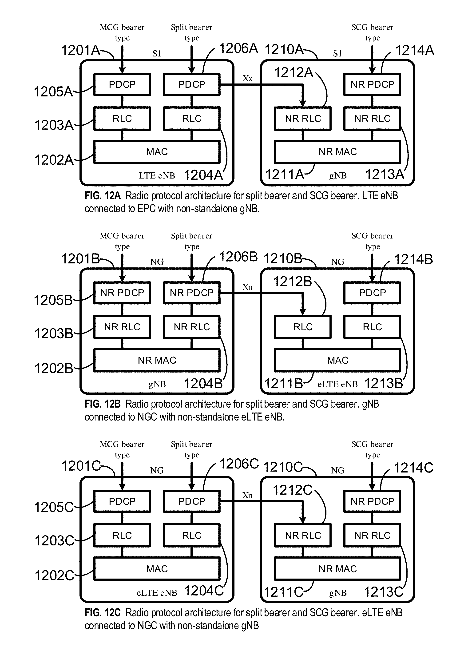
D00013
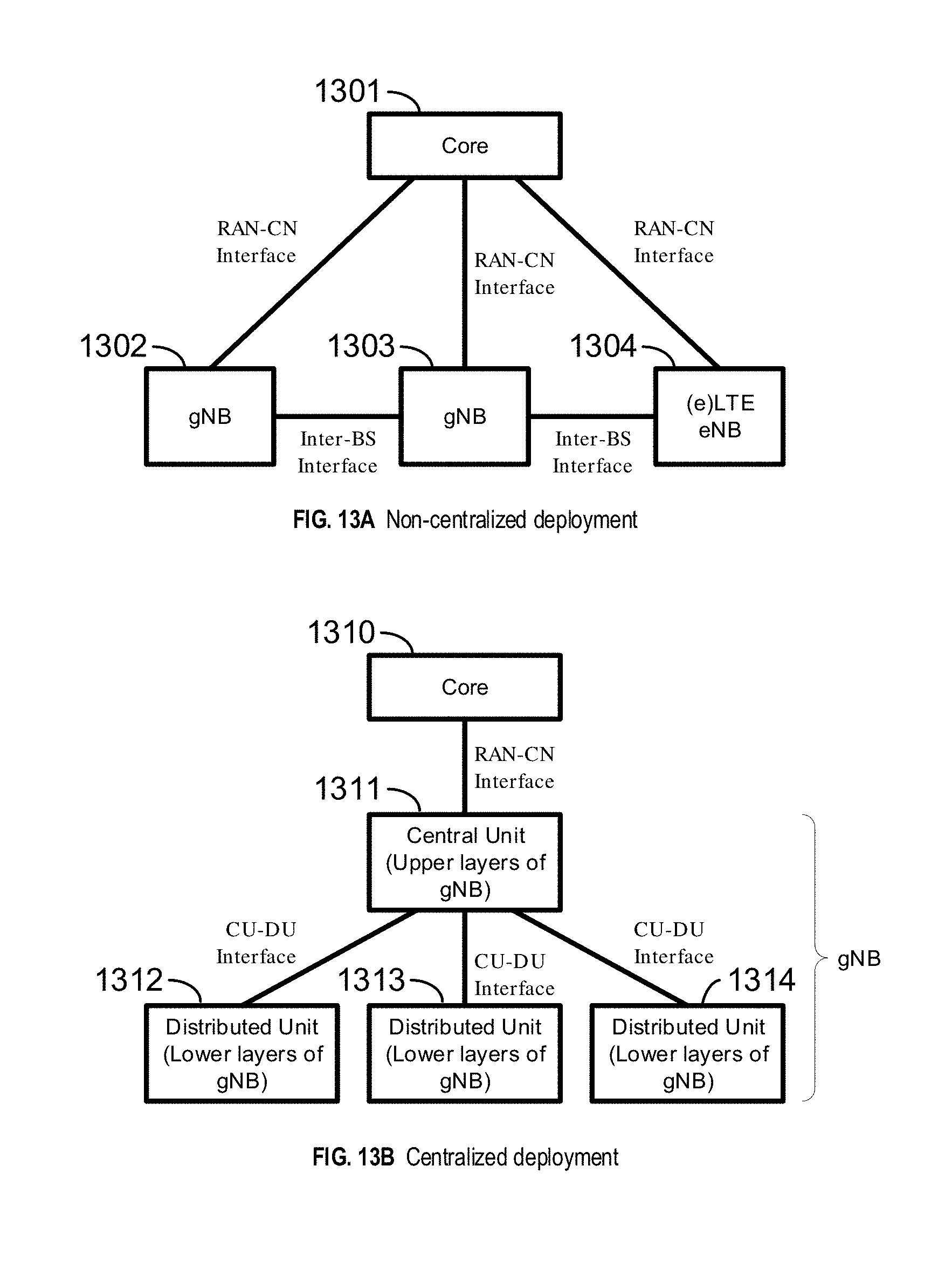
D00014

D00015
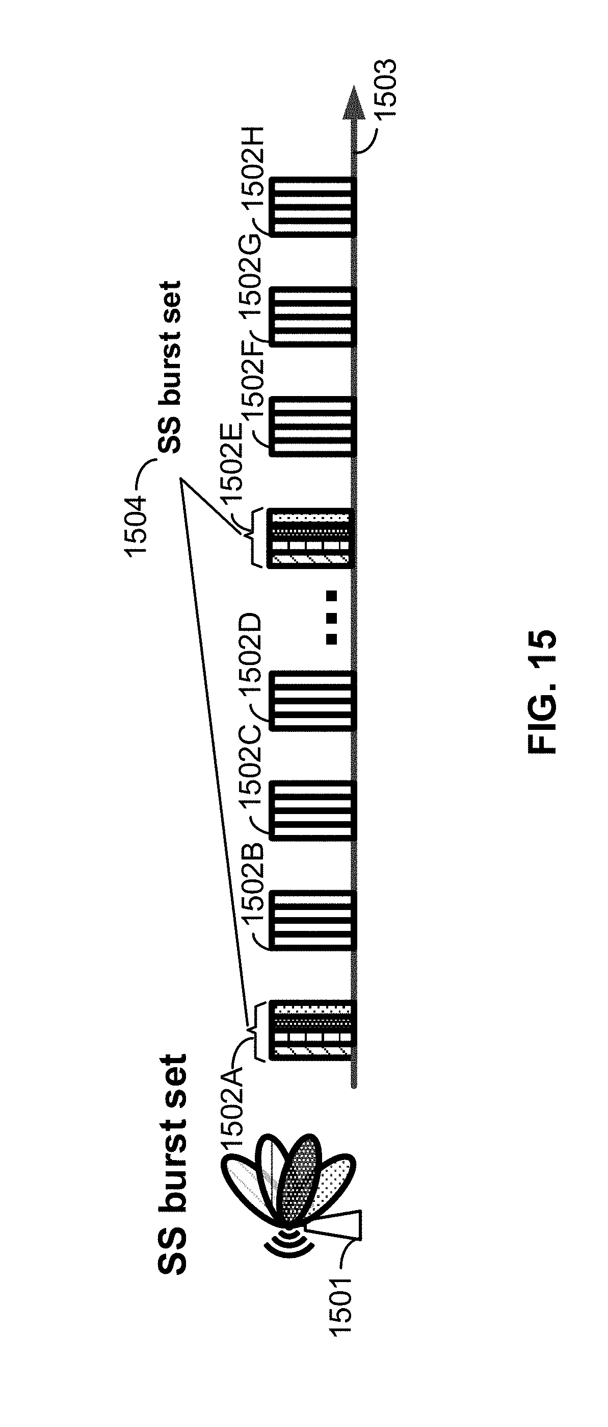
D00016
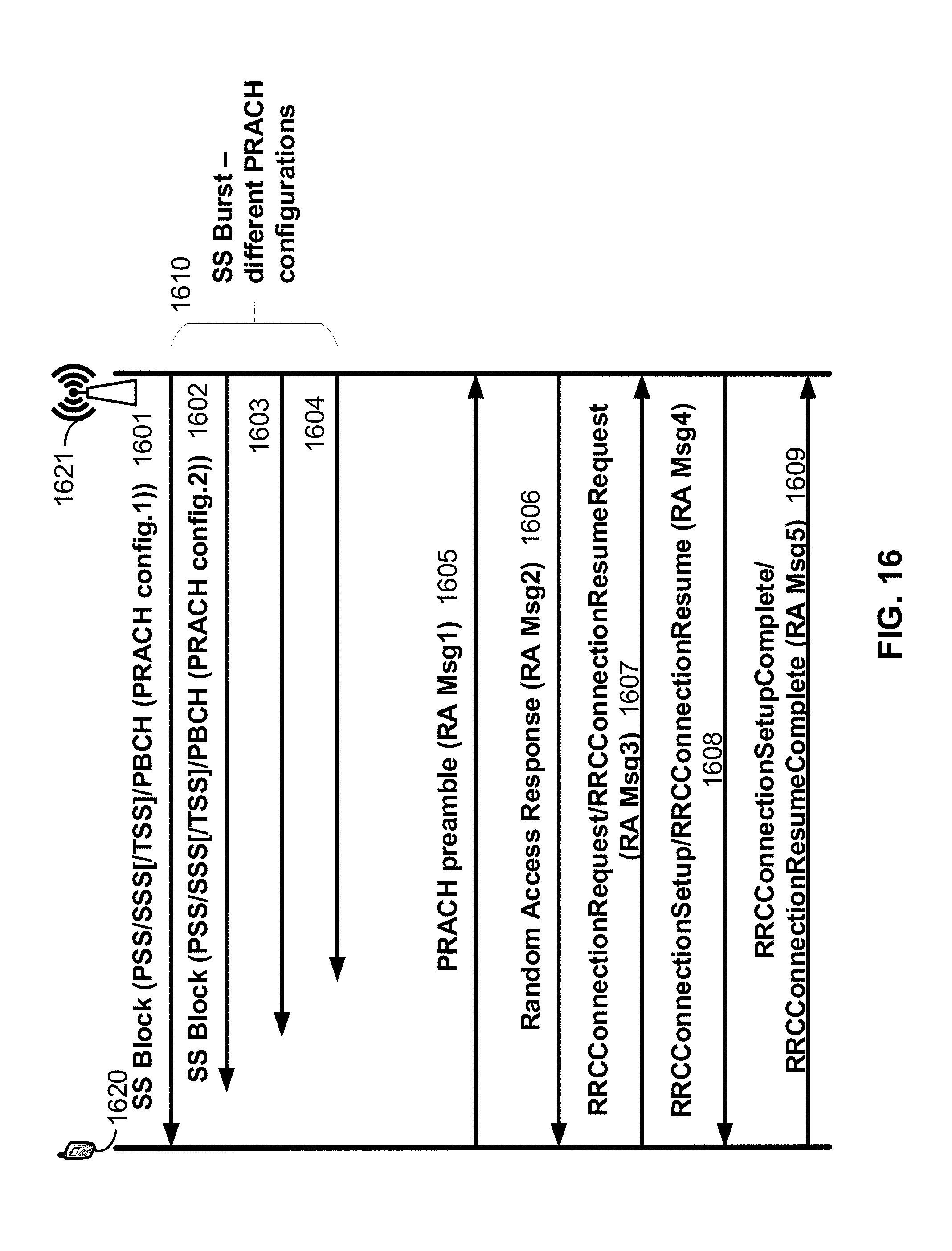
D00017
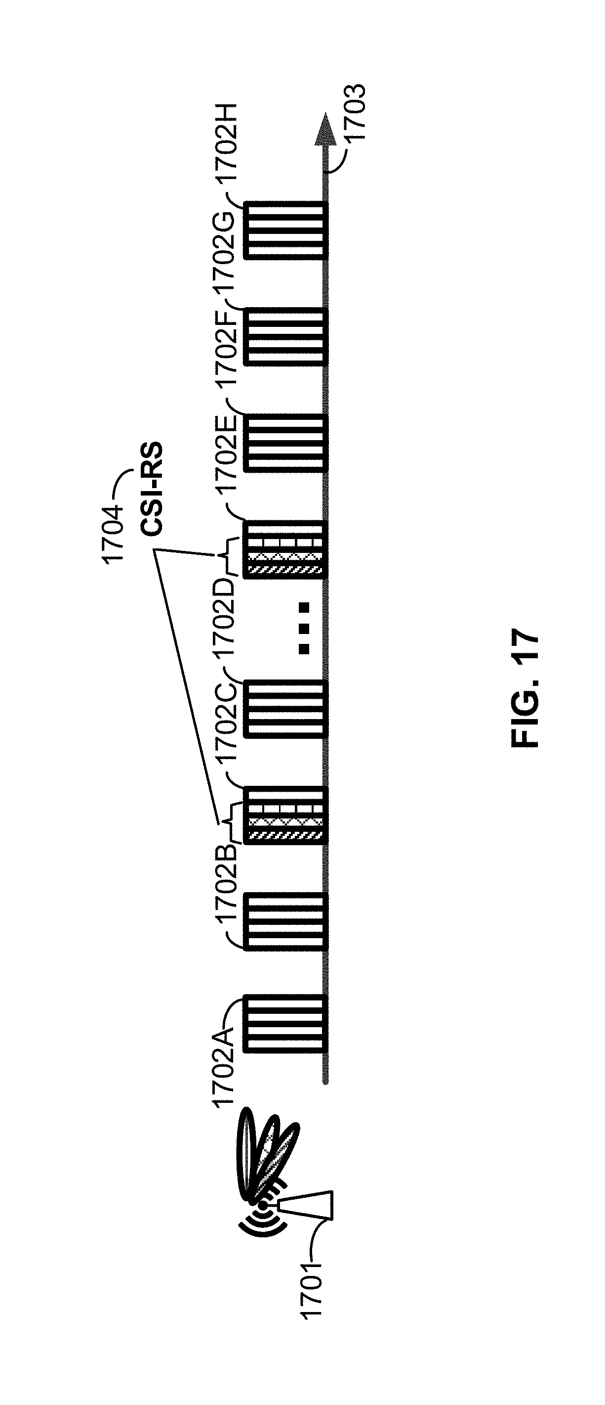
D00018

D00019
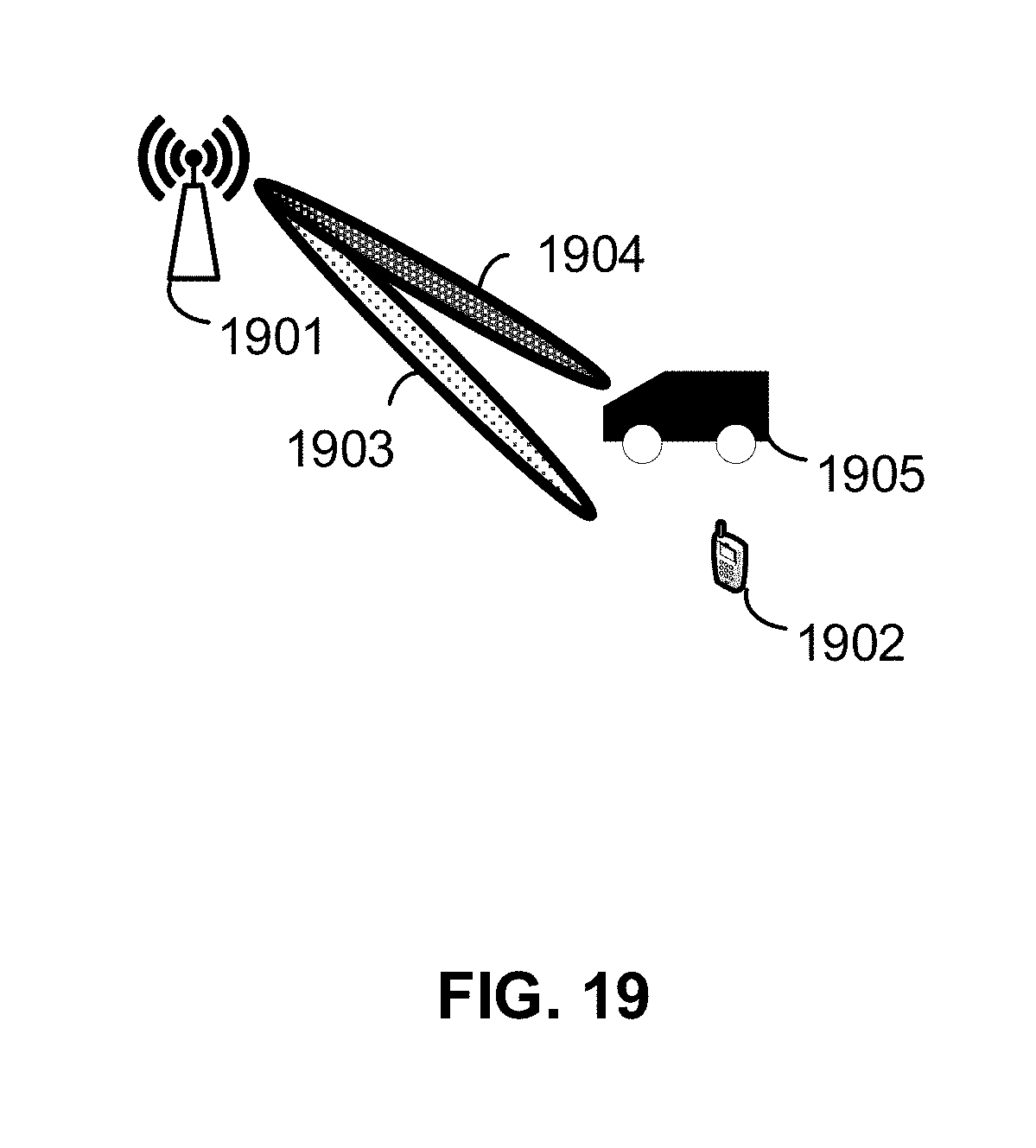
D00020
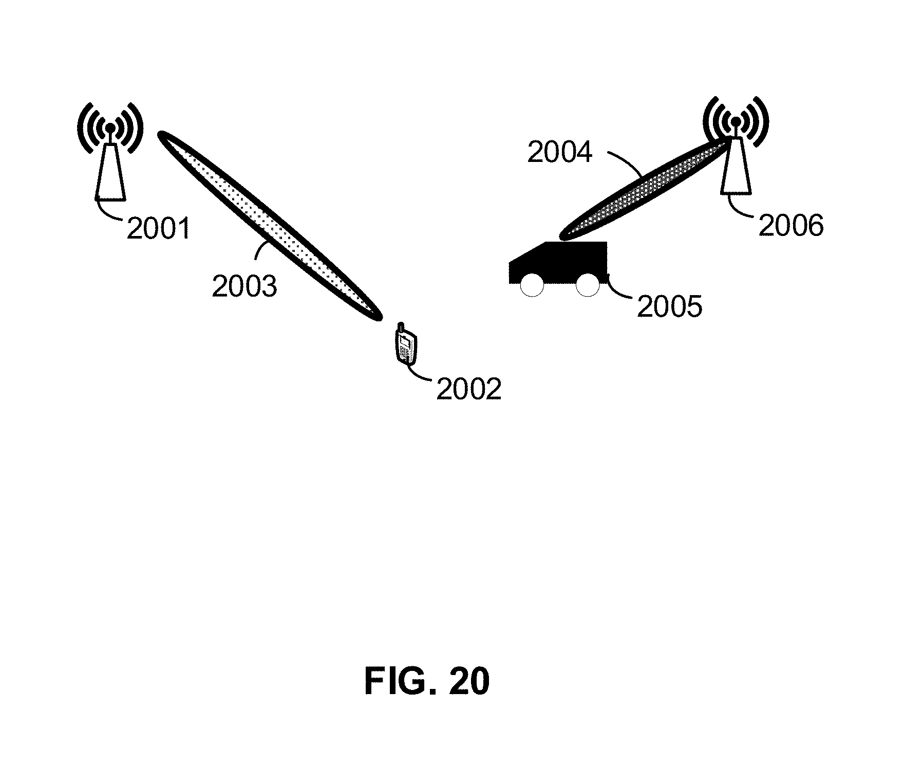
D00021
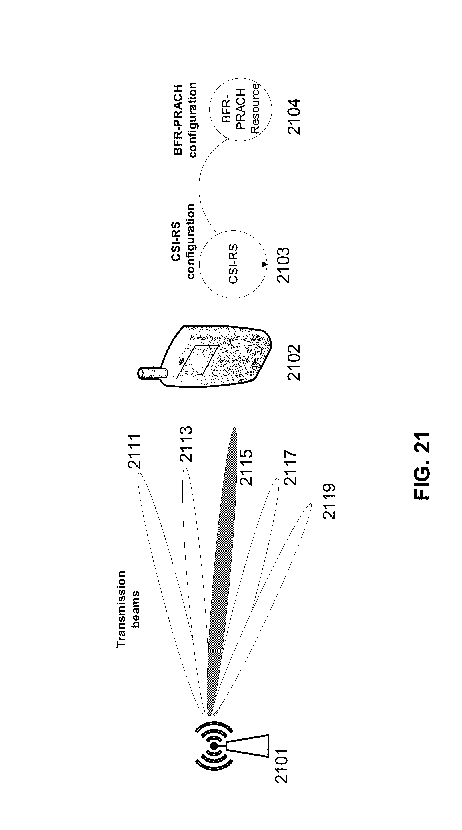
D00022

D00023
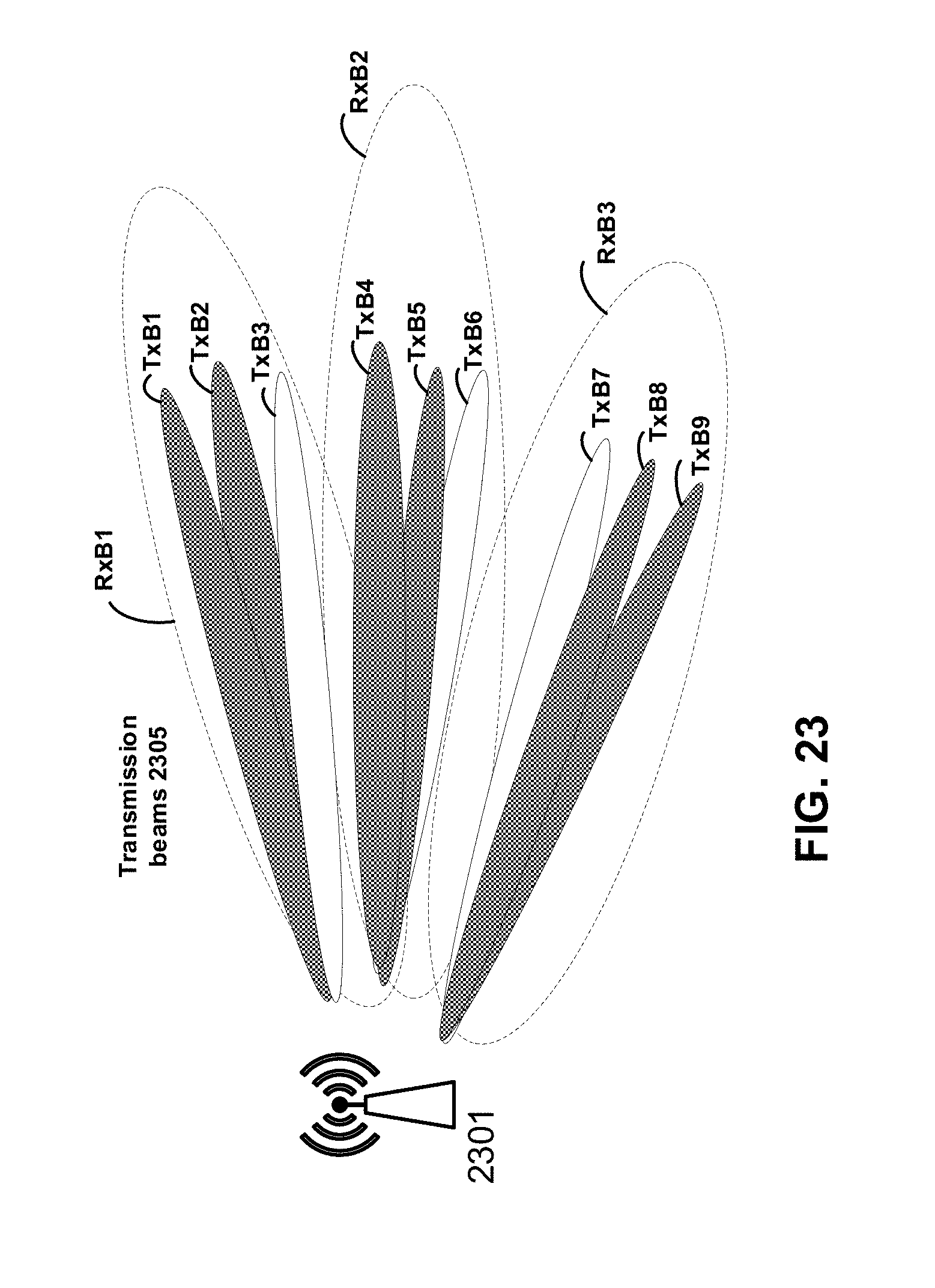
D00024

D00025
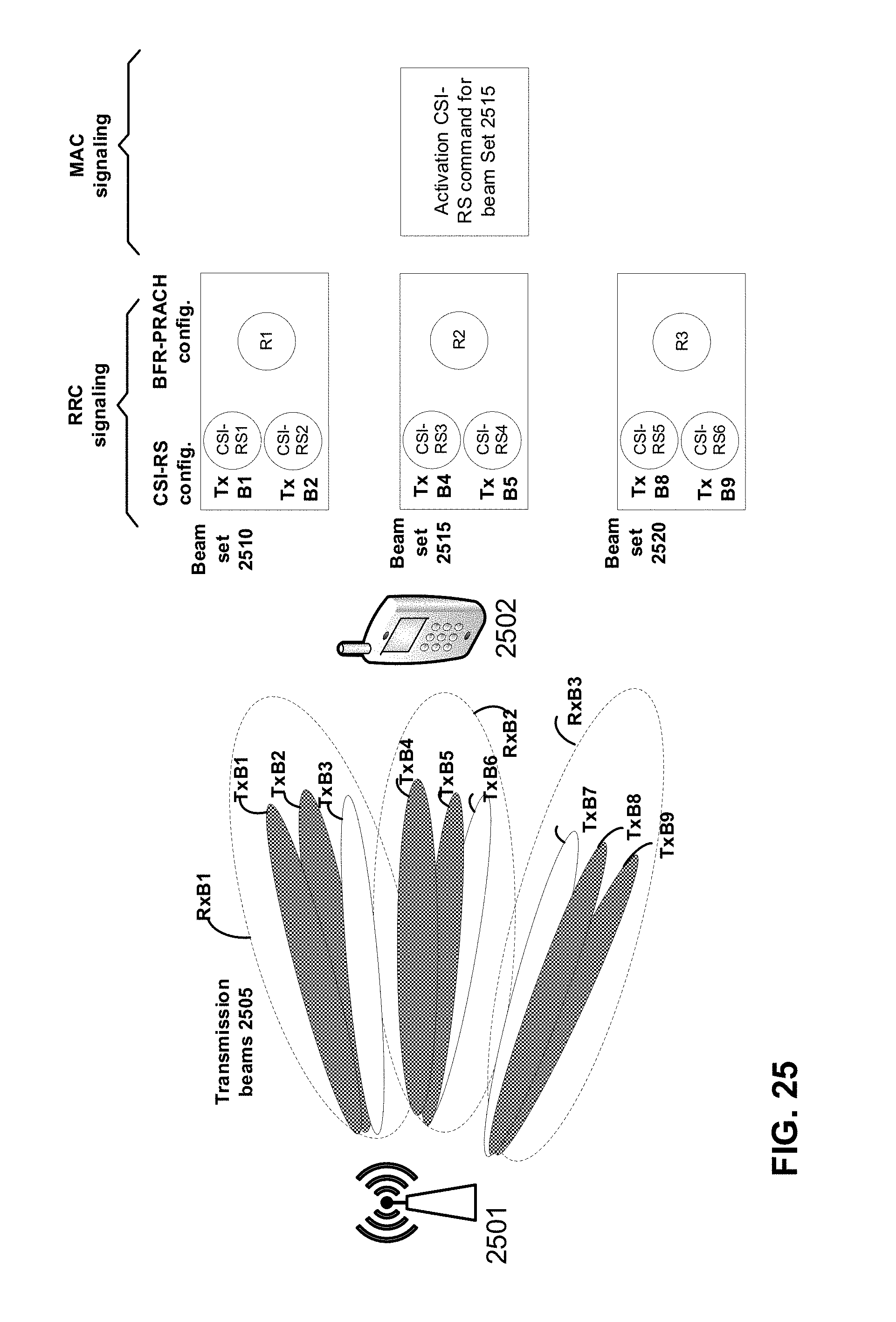
D00026
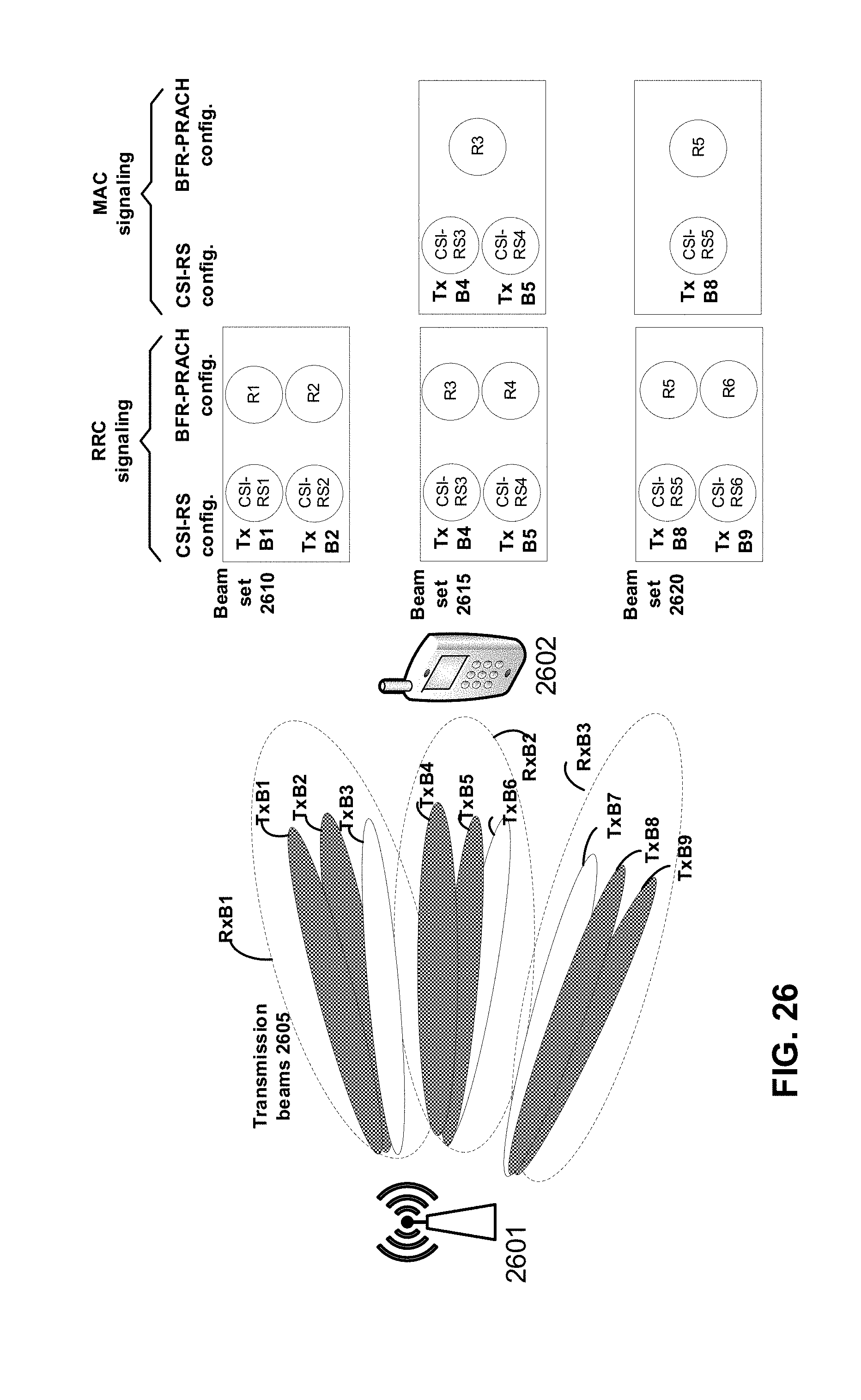
D00027

D00028
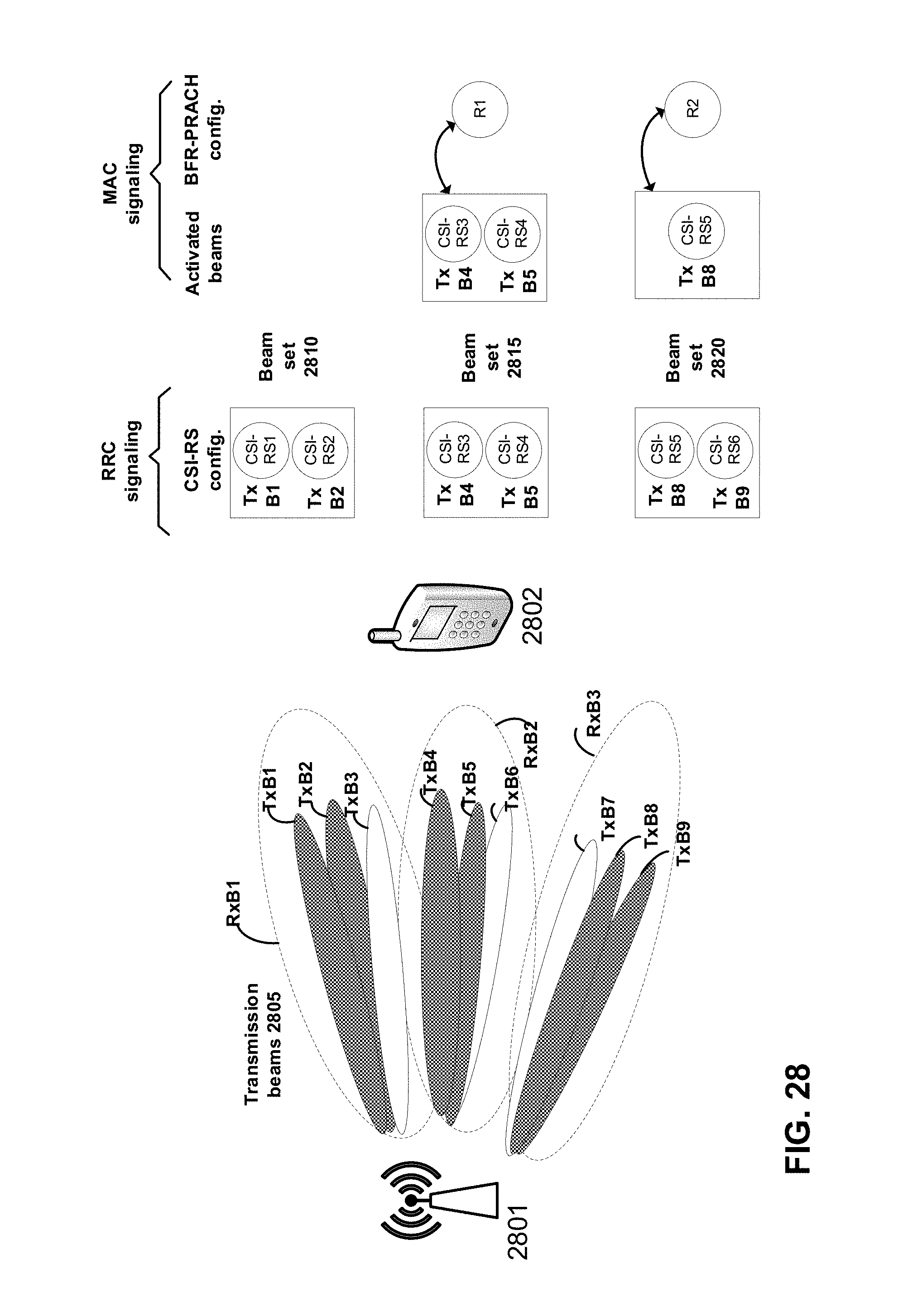
D00029
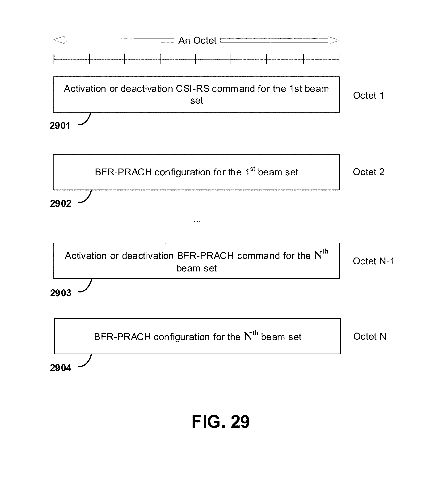
D00030

D00031
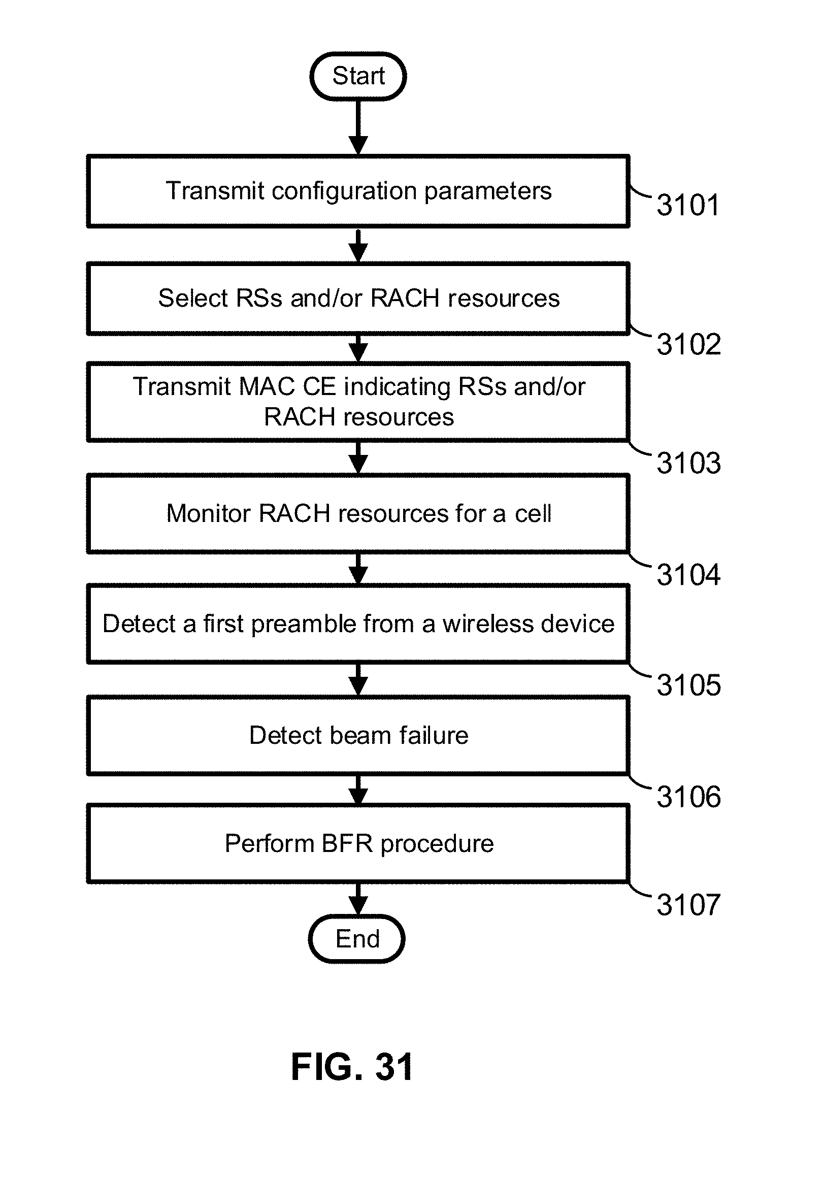
D00032
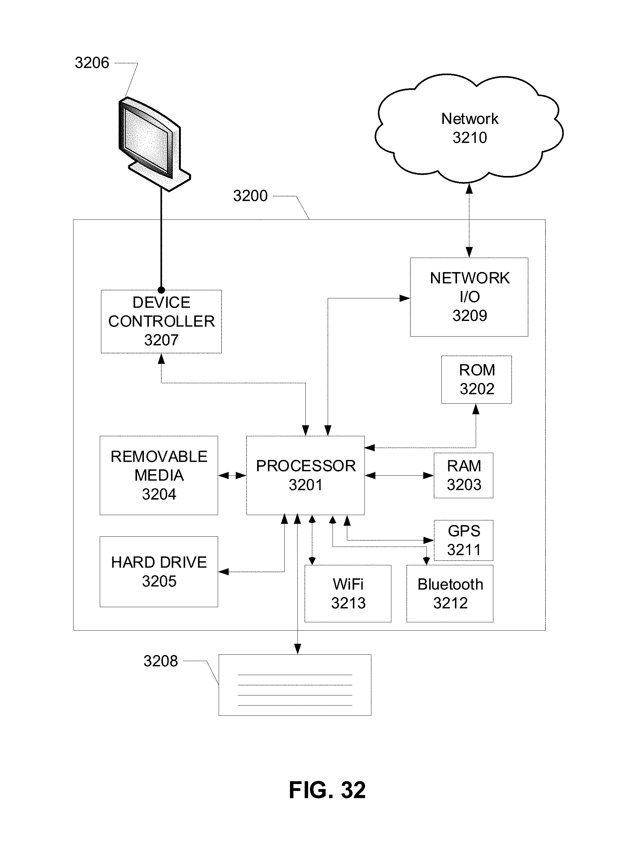
XML
uspto.report is an independent third-party trademark research tool that is not affiliated, endorsed, or sponsored by the United States Patent and Trademark Office (USPTO) or any other governmental organization. The information provided by uspto.report is based on publicly available data at the time of writing and is intended for informational purposes only.
While we strive to provide accurate and up-to-date information, we do not guarantee the accuracy, completeness, reliability, or suitability of the information displayed on this site. The use of this site is at your own risk. Any reliance you place on such information is therefore strictly at your own risk.
All official trademark data, including owner information, should be verified by visiting the official USPTO website at www.uspto.gov. This site is not intended to replace professional legal advice and should not be used as a substitute for consulting with a legal professional who is knowledgeable about trademark law.