Field Changeable Fiber Optic Connector Polarity Keying with Color Coding
Childers; Darrell R. ; et al.
U.S. patent application number 16/164382 was filed with the patent office on 2019-02-14 for field changeable fiber optic connector polarity keying with color coding. The applicant listed for this patent is US Conec, Ltd. Invention is credited to Darrell R. Childers, Craig M. Conrad, Jason Higley, Jillcha F. Wakjira, Myron W. Yount.
| Application Number | 20190049670 16/164382 |
| Document ID | / |
| Family ID | 59066054 |
| Filed Date | 2019-02-14 |

View All Diagrams
| United States Patent Application | 20190049670 |
| Kind Code | A1 |
| Childers; Darrell R. ; et al. | February 14, 2019 |
Field Changeable Fiber Optic Connector Polarity Keying with Color Coding
Abstract
A fiber optic connector along with a tool allows for the changing of the polarity of the fiber optic connector. Keys are installed in both the top and the bottom of the fiber optic connector, one in a first position and the other in a second position. Using the tool in one back-and-forth motion, the polarity of the fiber optic connector change be changed. The keys may be colored differently to identify the polarity of the fiber optic connector.
| Inventors: | Childers; Darrell R.; (Hickory, NC) ; Conrad; Craig M.; (Hickory, NC) ; Higley; Jason; (Hickory, NC) ; Wakjira; Jillcha F.; (Hickory, NC) ; Yount; Myron W.; (Conover, NC) | ||||||||||
| Applicant: |
|
||||||||||
|---|---|---|---|---|---|---|---|---|---|---|---|
| Family ID: | 59066054 | ||||||||||
| Appl. No.: | 16/164382 | ||||||||||
| Filed: | October 18, 2018 |
Related U.S. Patent Documents
| Application Number | Filing Date | Patent Number | ||
|---|---|---|---|---|
| 15881866 | Jan 29, 2018 | 10107969 | ||
| 16164382 | ||||
| 15383881 | Dec 19, 2016 | 9880361 | ||
| 15881866 | ||||
| 62269946 | Dec 19, 2015 | |||
| Current U.S. Class: | 1/1 |
| Current CPC Class: | G02B 6/3895 20130101; G02B 6/3821 20130101; G02B 6/3898 20130101; G02B 6/3885 20130101; G02B 6/3893 20130101; G02B 6/3831 20130101 |
| International Class: | G02B 6/38 20060101 G02B006/38 |
Claims
1-20. (canceled)
21. A fiber optic connector housing comprising: an inner connector housing having a top portion and a bottom portion connected by two side portions; an outer connector housing surrounding at least a portion of the inner connector housing; a key disposed in a recessed portion of the inner housing, the key having a front end and a rear end; and a latch adjacent the front end of the key, the latch having a surface facing the rear end of the key and configured to engage a forward facing surface disposed in the recessed portion of the inner housing thereby preventing the key from moving rearwardly upon application of a rearward force.
22. The fiber optic connector housing according to claim 21, further comprising a raised central member disposed within the recessed portion, the raised central member having the forward facing surface.
23. The fiber optic connector housing according to claim 21, wherein the front end has a first thickness and the rear end has a second thickness, the first thickness being greater than the second thickness.
24. The fiber optic connector housing according to claim 21, wherein the latch is part of a tab integrally formed with the key.
25. The fiber optic connector housing according to claim 21, further comprising a second latch to engage a rearward facing surface in the recessed portion to prevent removal of the key from the fiber optic connector housing.
26. The fiber optic connector according to claim 21, wherein the front end of the key has a wall to guard the latch.
27. The fiber optic connector according to claim 21, wherein the recessed portion has a rear wall to provide a stop for the key in a retracted position.
28. The fiber optic connector according to claim 21, wherein the key and the recessed portion form a sliding dovetail.
29. A key to be disposed in a recessed portion of a fiber optic connector housing comprising: a front end and a rear end; a first latch having a surface facing the rear end of the key and to engage the forward facing surface in the recessed portion of the fiber optic connector housing to prevent the key from moving rearwardly upon application of a rearward force to the key.
30. The key according to claim 29, further comprising at least one tab, the at least one tab disposed between the front and rear ends and having the first latch disposed thereon.
31. The key according to claim 29, further comprising a second tab, the second tab disposed between the at least one tab and rear end.
31. The key according to claim 30, further comprising a central opening, the central opening extending along a portion of key between the front and rear ends, the at least one tab extending at least partially into the central opening.
32. The key according to claim 29, further comprising a second latch to engage a rearward facing surface in the recessed portion to prevent removal of the key from the fiber optic connector housing.
33. The key according to claim 29, further comprising a flared portion along opposing edges.
34. The key according to claim 29, wherein the front end of the key has a wall to guard the first latch.
35. The key according to claim 29, wherein the first end has a first thickness and the second end has a second thickness, the first thickness being greater than the second thickness.
36. A tool for moving at least one key in a fiber optic connector to change the polarity of the fiber optic connector comprising: a body configured to receive at least a portion of an inner housing of the fiber optic connector, the body having a first side and an opposing second side; a prong extending from the first side to engage a latch on the key and move the latch away from the inner housing as the body is moved relative to the inner housing; at least one extension on the first side of the body to engage a portion of the key to move the key rearwardly as the body is moved rearwardly.
37. The tool according to claim 36, further comprising two protrusions disposed on the second side of the body, the protrusions configured to engage a key in the fiber optic connector.
Description
REFERENCE TO RELATED CASE
[0001] This application claims priority under 35 U.S.C. .sctn. 119 (e) to provisional application No. 62/269,946 filed on Dec. 19, 2015, the contents of which are hereby incorporated by reference in their entirety.
BACKGROUND OF THE INVENTION
Field of the Invention
[0002] Fiber optic jumper cables are used to connect various pieces of telecommunications equipment. These fiber optic jumper cables typically have 12 or more optical fibers in them and are terminated using fiber optic ferrules. The fiber optic jumper cables are either plugged directly into telecommunications equipment (e.g., a transceiver, etc.) or are connected to another fiber optic jumper cable by use of an adapter. Since the fiber optic jumper cables have a number of optical fibers, the routing of those optical fibers is important to ensure that signals traveling on the optical fibers reach the intended destination and in the correct position in the telecommunications equipment or the other fiber optic jumper cable. Thus, the fiber optic jumper cables have a polarity, which is dictated by the positioning of the optical fibers secured in the fiber optic ferrules. Each of the fiber optic ferrules has a particular orientation, and the relationship of the position of the optical fibers to the fiber optic ferrule determines the polarity. However, there are times that the polarity of the fiber optic connector needs to be changed in the field due to changes in the routing, equipment, or design, or simply because the customer ordered the incorrect polarity. However, changing the polarity in the field would require that the connector housing be changed, while the optical fibers are attached. This is tricky, time consuming, and, most importantly, may damage the connector, the optical fibers or the entire fiber optic jumper cable.
[0003] Thus, a fiber optic connector that allows for the polarity to be changed in the field without removing any of other components of the fiber optic connector is needed.
SUMMARY OF THE INVENTION
[0004] The present invention is directed to fiber optic connector that includes a fiber optic ferrule, an inner connector housing surrounding at least a portion of the fiber optic ferrule, the inner connecting housing having a top portion and a bottom portion connected by two side portions, the top and bottom portions having an outer surface and a thickness, an outer connector housing surrounding at least a portion of the inner connector housing, the outer connector housing movable relative to the inner connector housing, a top recessed portion on the top portion of the inner connector housing, the top recessed portion extending into the thickness of the top portion, a bottom recessed portion on the bottom portion of the inner connector housing, the bottom recessed portion extending into the thickness of the bottom portion, a forward facing surface and a rearward facing surface disposed in each of the top and bottom recessed portions, and a key to be disposed within one of the top recessed portion and the bottom recessed portion, the key having a first latch to engage the forward facing surface in a first position and a second latch to engage the rearward facing surface to prevent removal of the key from the fiber optic connector.
[0005] In some embodiments, the recessed portion has a rear wall to provide a stop for the key in a second position.
[0006] In some other embodiments, the key and the recessed portion form a sliding dovetail.
[0007] In another embodiment, a method of changing the polarity of a fiber optic connector is provided. In this method, the fiber optic connector having a connector housing has a first key in a first portion of the connector housing in a first position and a second key in a second portion of the connector housing in a second position, the method includes aligning a tool with the connector housing, the tool having a chamfered leading edge on a first side and two protrusions on a second side, pushing the tool onto a front end of the fiber optic connector so that the chamfered leading edge engages the first key by lifting a portion of the first key over a first edge and then rearwardly until the tool and first key stop and the two protrusions on the second side of the tool engage corresponding notches in the second key, and pulling the tool toward the front end of the fiber optic connector thereby leaving the first key in a second position and bringing the second key therewith, the second key disengaging from the tool when a portion of the second key engages a second edge thereby changing the polarity of the fiber optic connector.
[0008] According to another aspect of the present invention, there is a fiber optic connector that includes a fiber optic ferrule, an inner connector housing surrounding at least a portion of the fiber optic ferrule, the inner connecting housing having a top portion and a bottom portion connected by two side portions, the top and bottom portions having an outer surface and a thickness, an outer connector housing surrounding at least a portion of the inner connector housing, the outer connector housing movable relative to the inner connector housing, a top recessed portion on the top portion of the inner connector housing, the top recessed portion extending into the thickness of the top portion, a bottom recessed portion on the bottom portion of the inner connector housing, the bottom recessed portion extending into the thickness of the bottom portion, a forward facing surface and a rearward facing surface disposed in each of the top and bottom recessed portions, and a first key to be disposed within the top recessed portion and a second key disposed within the bottom recessed portion, each of the first and second keys having a first latch to engage the forward facing surface in a first position and a second latch to engage the rearward facing surface to prevent removal of the first and second keys from the fiber optic connector.
[0009] It is to be understood that both the foregoing general description and the following detailed description of the present embodiments of the invention are intended to provide an overview or framework for understanding the nature and character of the invention as it is claimed. The accompanying drawings are included to provide a further understanding of the invention and are incorporated into and constitute a part of this specification. The drawings illustrate various embodiments of the invention, and together with the description, serve to explain the principles and operations of the invention.
BRIEF DESCRIPTION OF THE DRAWINGS
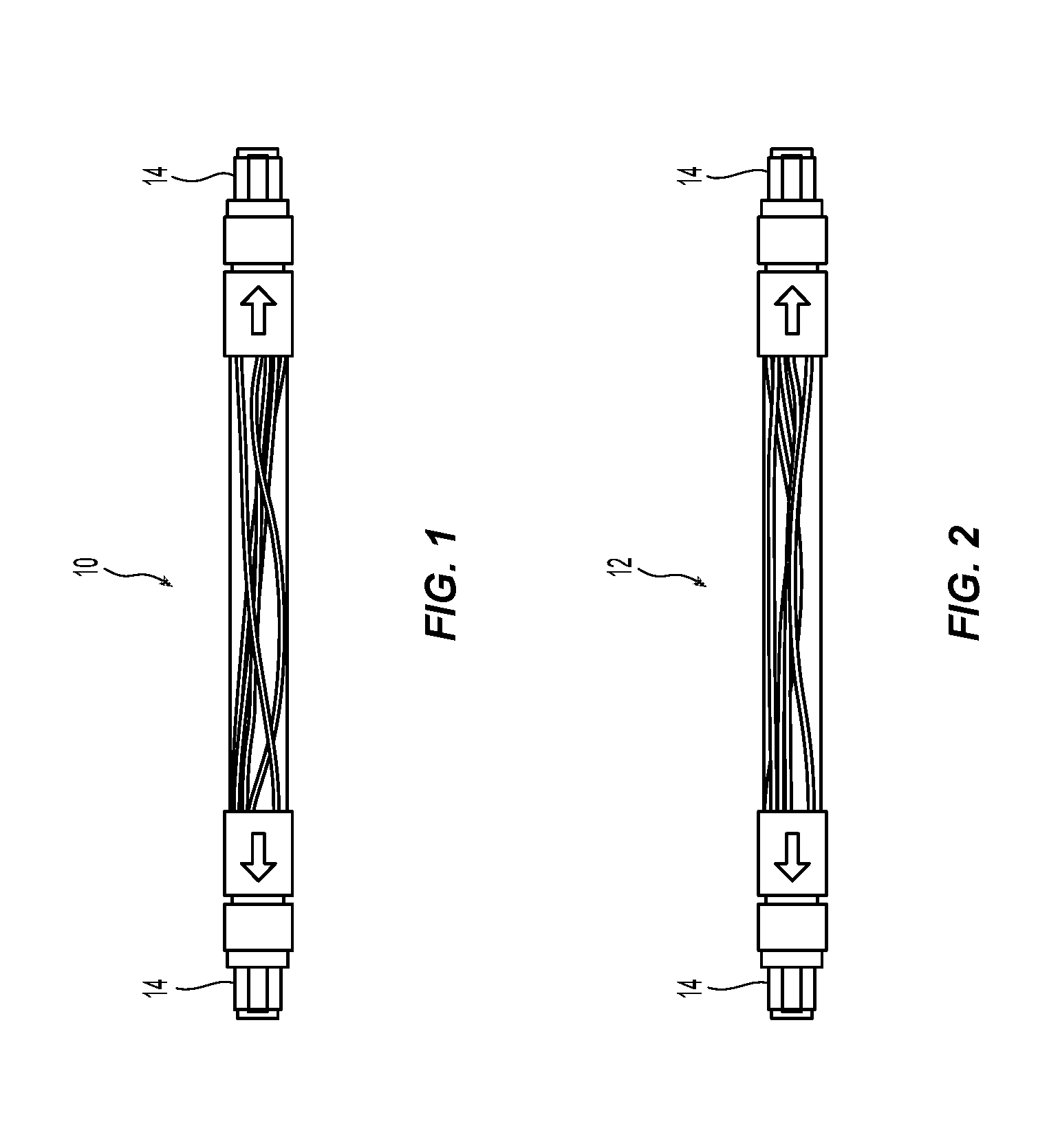
[0010] FIG. 1 is a planar view of a Type A jumper;
[0011] FIG. 2 is a planar view of a Type B jumper;
[0012] FIG. 3 illustrates a connectivity method for using Type A adapters;
[0013] FIG. 4 illustrates a connectivity method for using Type B adapters;
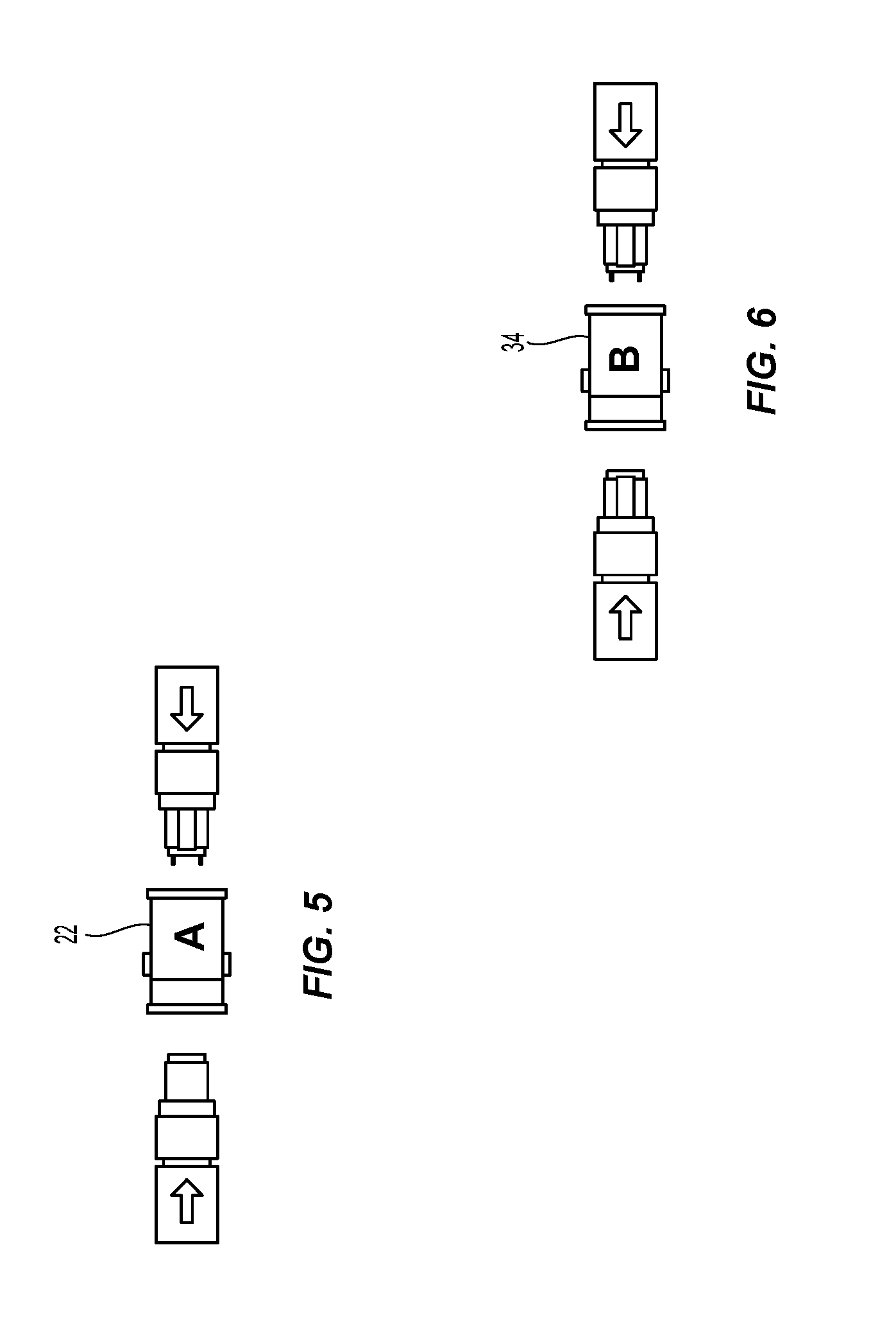
[0014] FIG. 5 illustrates the Type A adapters;
[0015] FIG. 6 illustrates the Type B adapters;
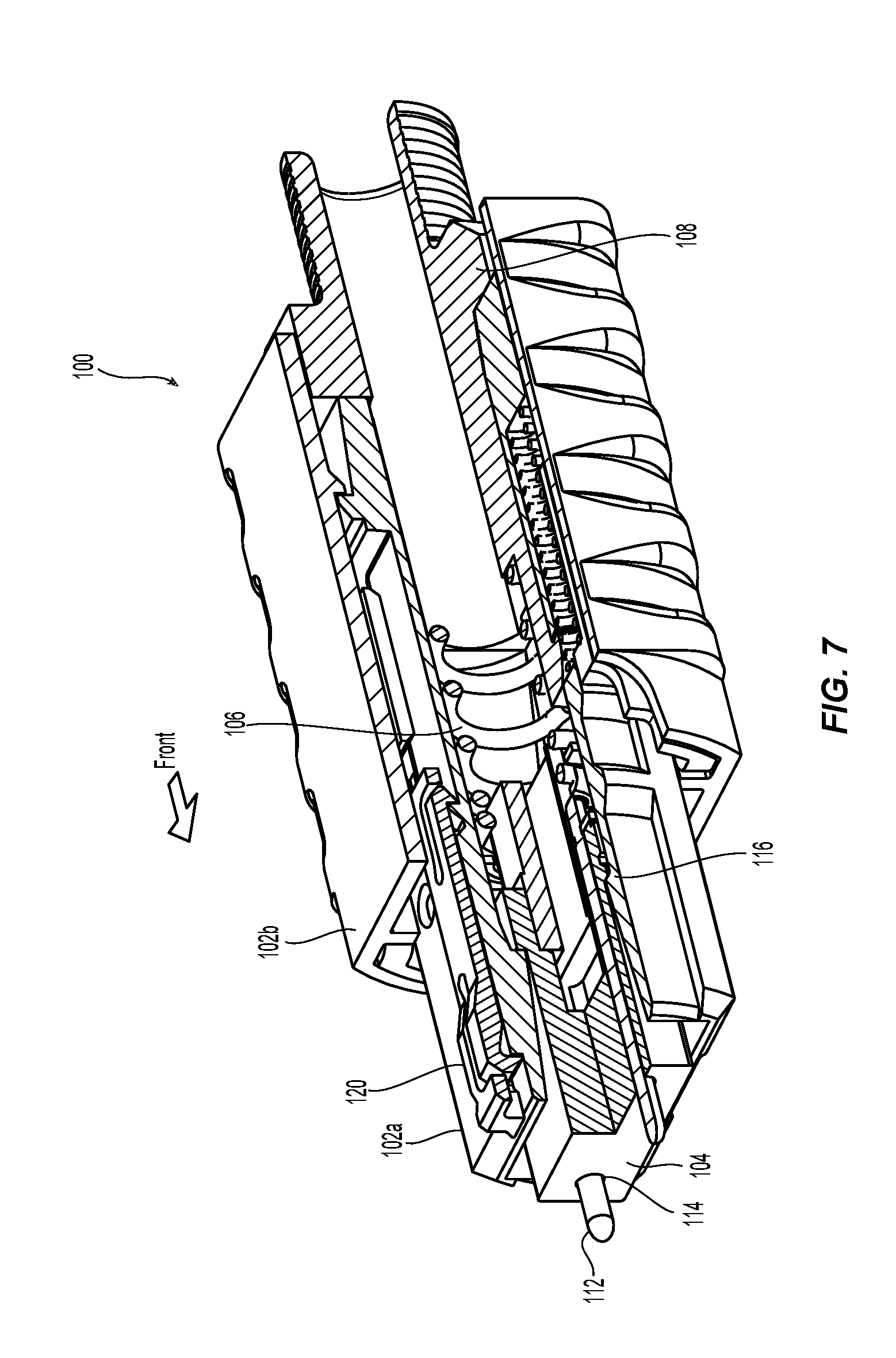
[0016] FIG. 7 is a partial cross section view of one embodiment of the fiber optic connector having two keys according to the present invention;
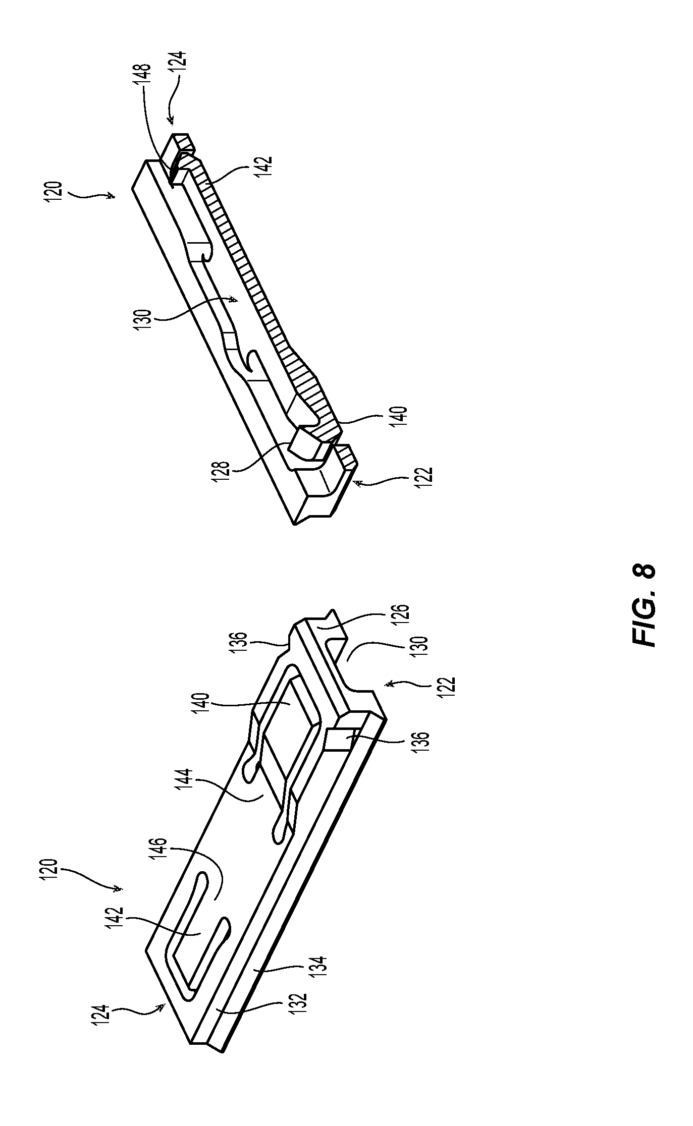
[0017] FIG. 8 is a perspective view of one embodiment of a key according to the present invention and a cross section of that key;
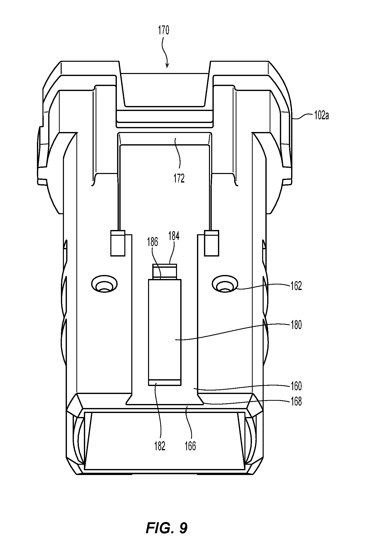
[0018] FIG. 9 is a front perspective view of one embodiment of an inner connector housing according to the present invention showing the top of the inner connector housing (the bottom side being the same);
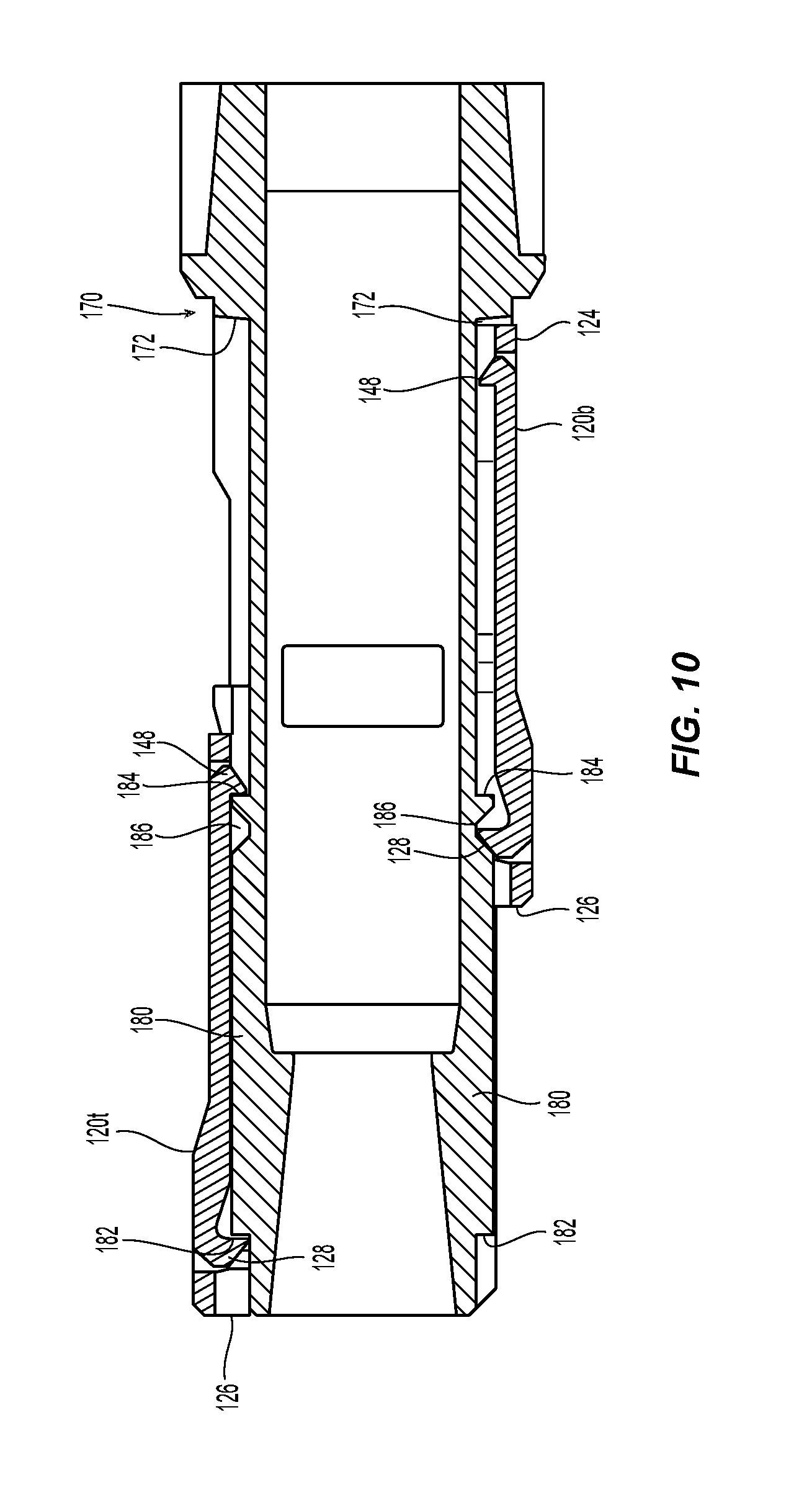
[0019] FIG. 10 is a cross sectional view of the inner connector housing of FIG. 9 and two keys according to FIG. 8 in a first position and a second position;
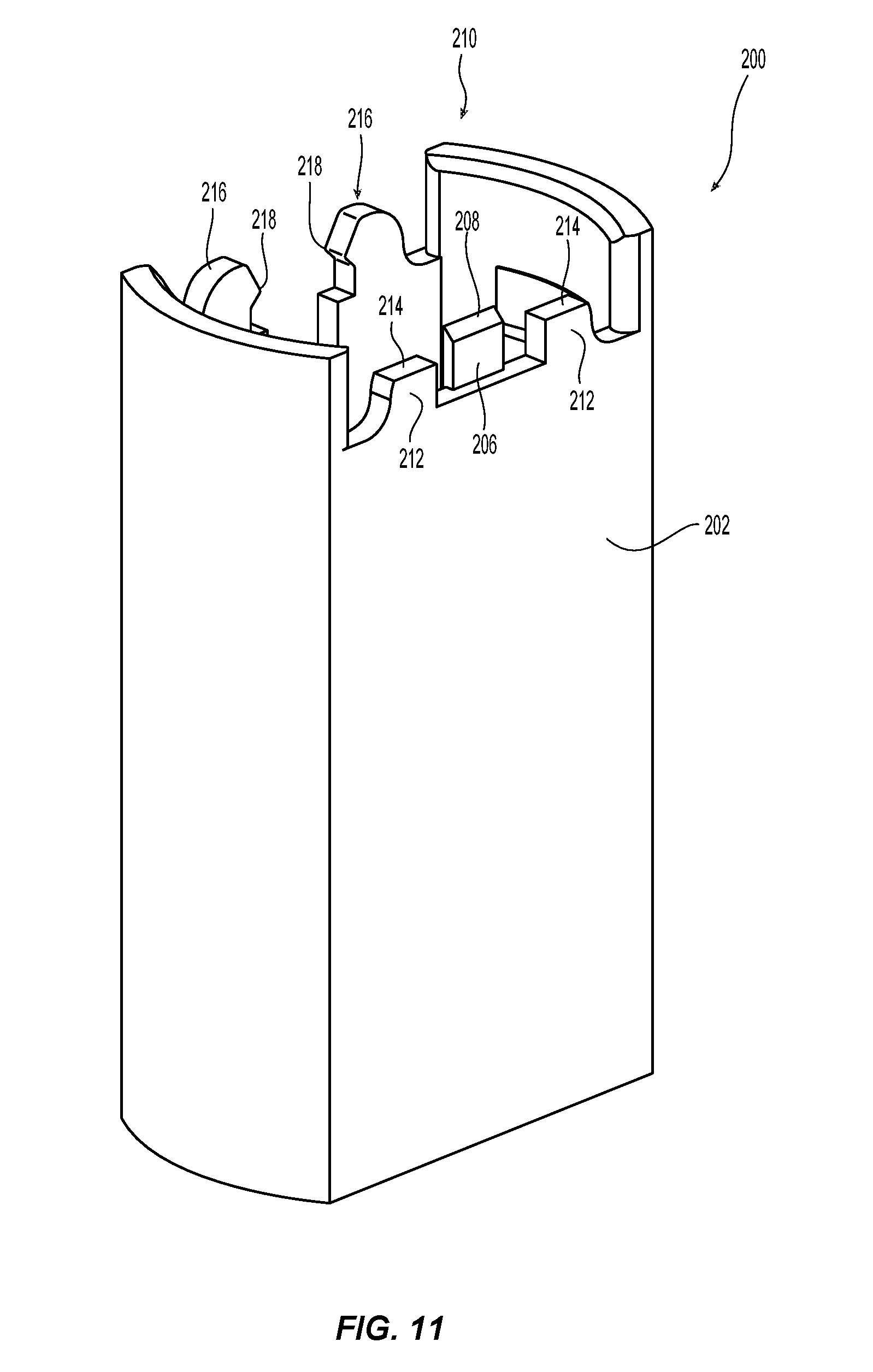
[0020] FIG. 11 is a perspective view of one embodiment of a tool to be used with the fiber optic connector of FIG. 7;
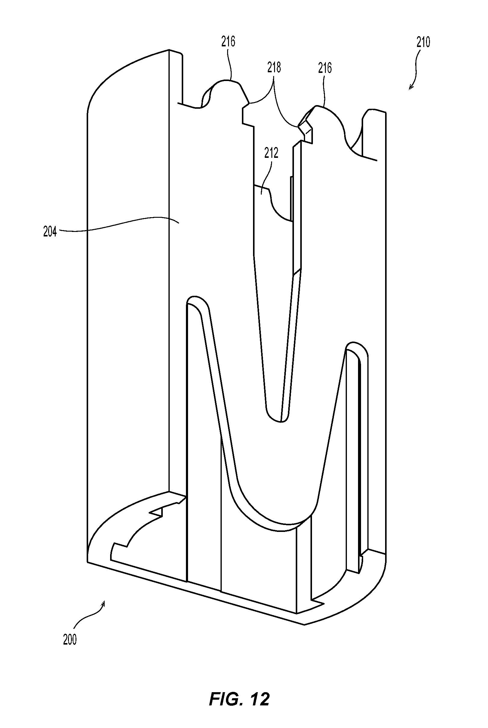
[0021] FIG. 12 is a perspective view of the tool in FIG. 11 from the opposite side;
[0022] FIG. 13 is a cross section along a longitudinal axis of the tool in FIG. 11;
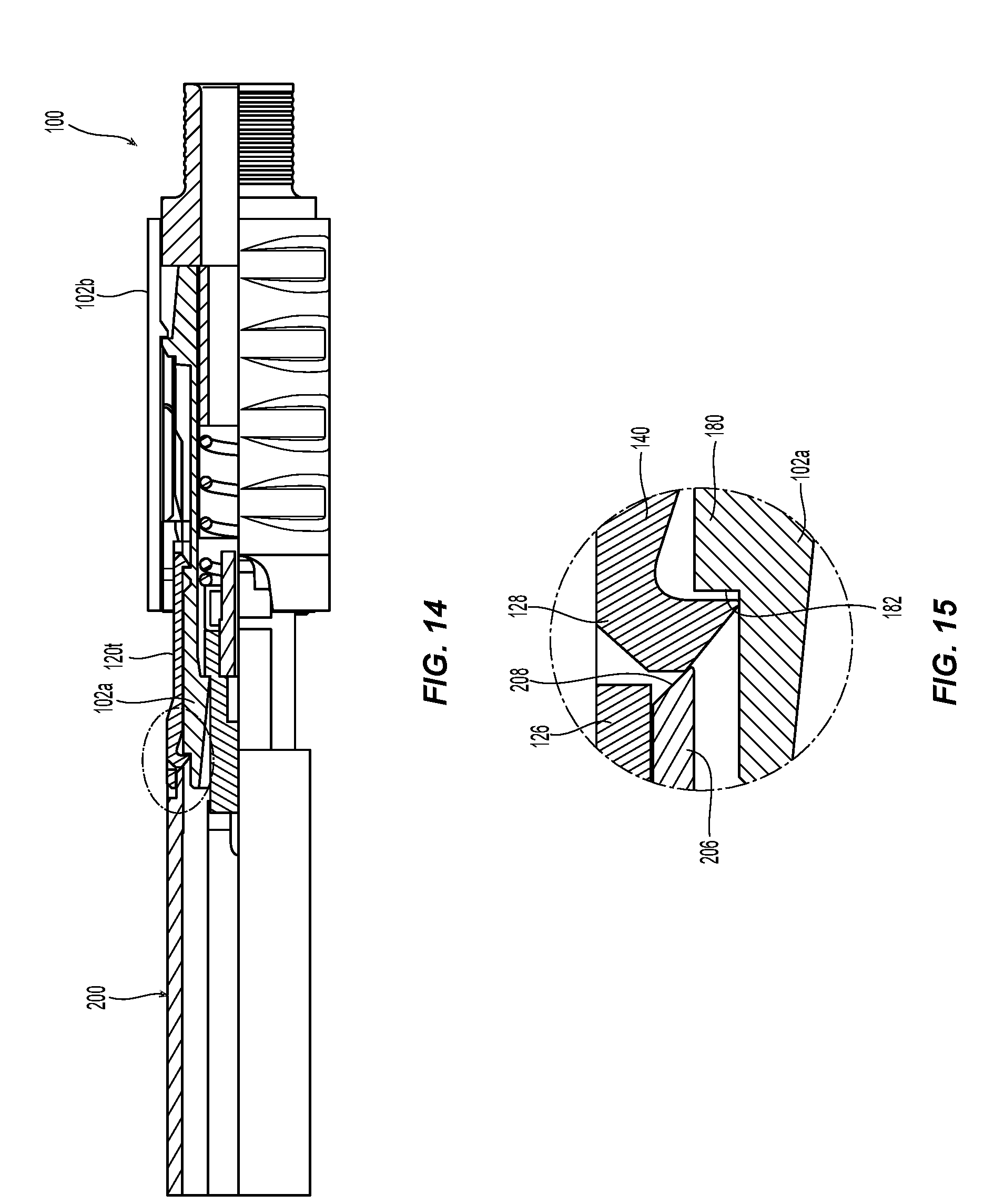
[0023] FIG. 14 is a partial cross section of the fiber optic connector with the tool in a starting position on the fiber optic connector;
[0024] FIG. 15 is a detail view of the chamfered leading edge of the tool of FIGS. 11-13 engaging one key to reverse polarity of the fiber optic connector;
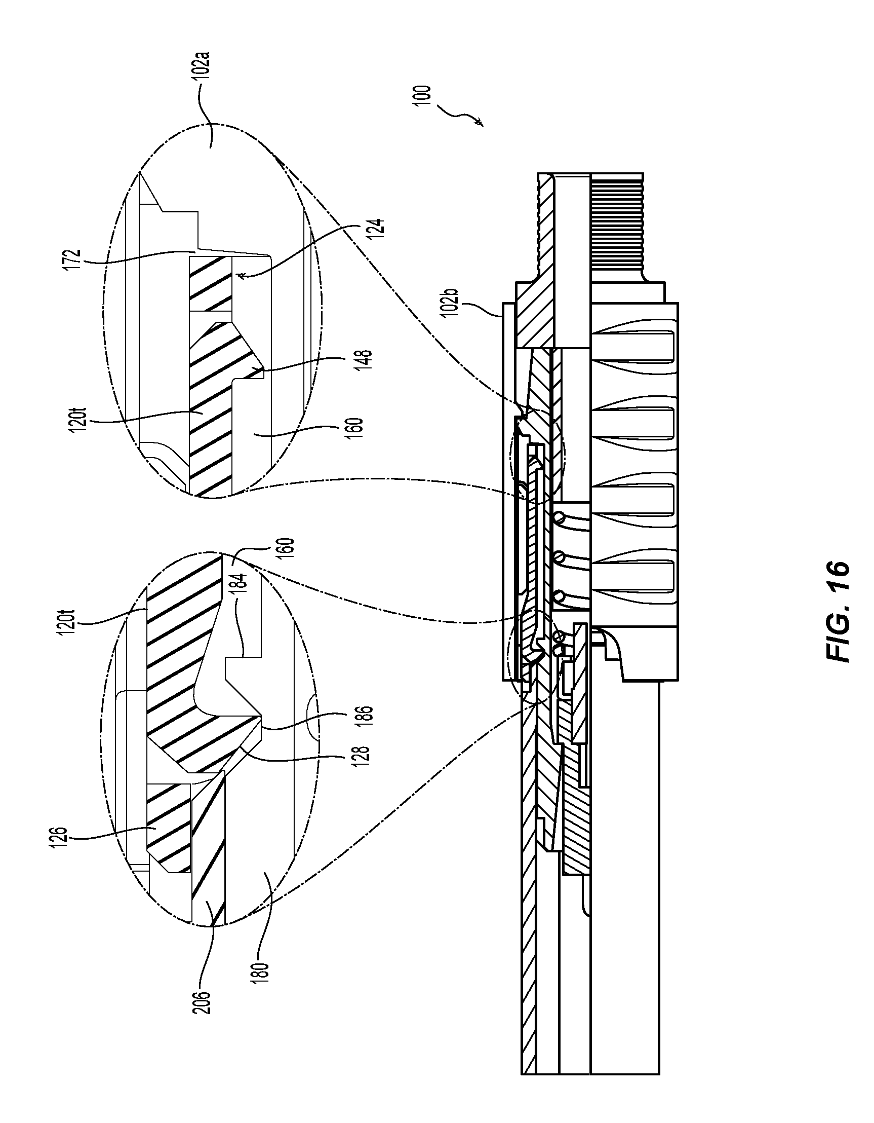
[0025] FIG. 16 is a partial cross section of the fiber optic connector with two detail drawings showing the first key in the second position with a first latch in the indentation and the rearward end of the key against the key stop;
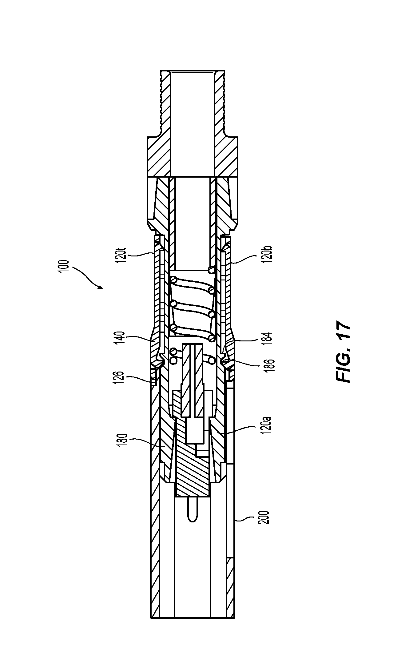
[0026] FIG. 17 is a cross section of the fiber optic connector with the tool engaging the second of the two keys to pull the second key forward;
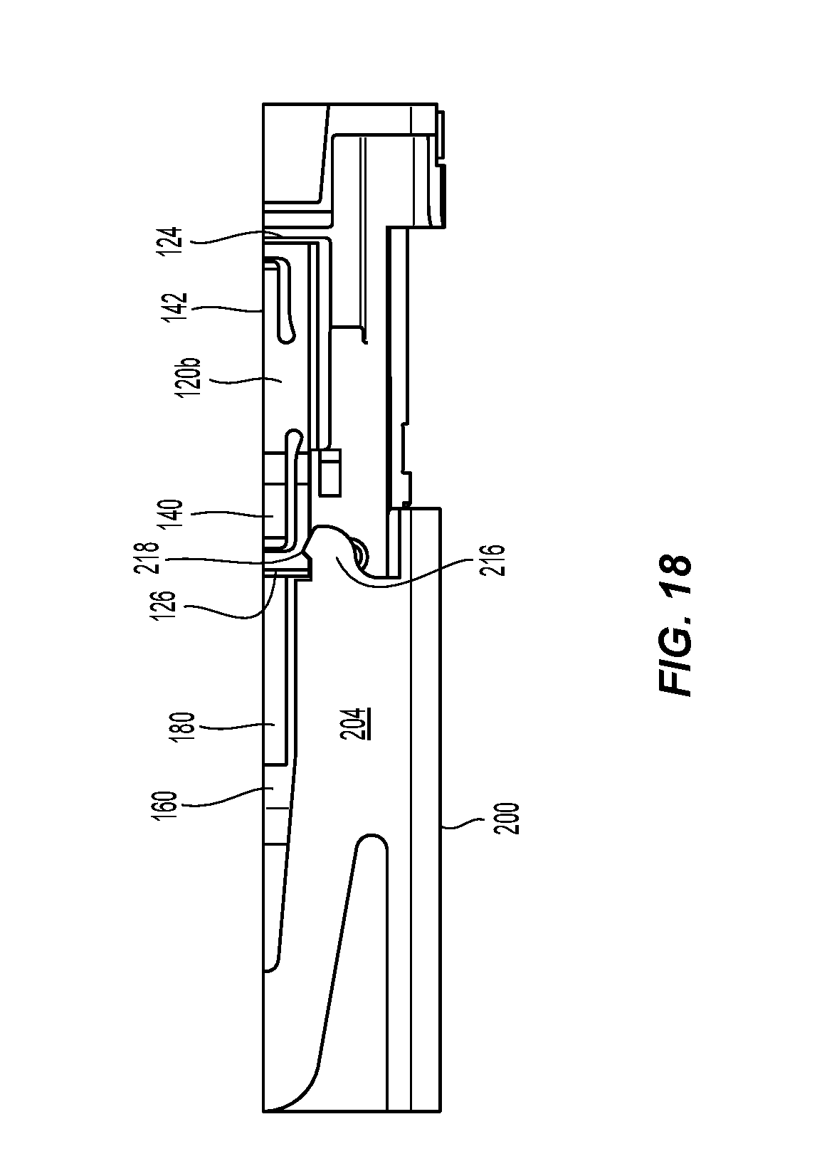
[0027] FIG. 18 is a partial underside view of the protrusions of the tool engaging the second key as illustrated in FIG. 17;
[0028] FIG. 19 is an underside view of the tool, key and inner connector housing showing the second key in the first position after the tool is pulled forward; and
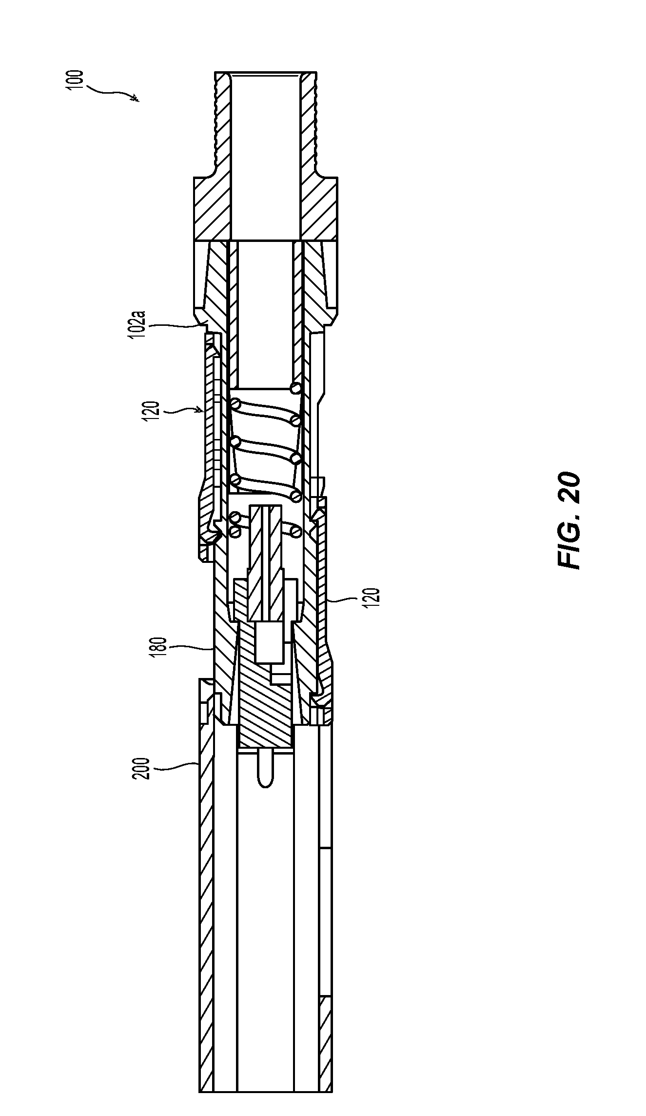
[0029] FIG. 20 is a cross section view of the fiber optic connector illustrating the first key in the second position and the second key in the first position as also illustrated in FIG. 19, thus reversing the polarity of the fiber optic connector.
DETAILED DESCRIPTION OF THE PREFERRED EMBODIMENTS
[0030] Reference will now be made in detail to the present preferred embodiment(s) of the invention, examples of which are illustrated in the accompanying drawings. Whenever possible, the same reference numerals will be used throughout the drawings to refer to the same or like parts.
[0031] Further to the above discussion, illustrated in FIGS. 1-6 are components of a fiber optic jumper cable, the adapters and routing pattern of the optical fibers. There are two types of fiber optic jumper cables, which are illustrated in FIGS. 1 and 2. In FIG. 1 is a Type A fiber optic jumper cable 10 while FIG. 2 is a Type B fiber optic jumper cable 12. In a Type A fiber optic jumper cable, the optical fibers are in the same position at both ends (as one looks at the end of the fiber optic ferrule with the keys 14, in the same direction). It should be noted that with the keys up at both ends in a TypeA fiber optic jumper cable, the fibers are crossed over the length of the jumper. If the keys were opposite (one of the keys not pointing up, but rather down into the page, then the optical fibers would appear to run straight from one end to the other). In a Type B fiber optic jumper cable, the optical fibers are reversed. For example, the optical fiber in position 1 in one fiber optic ferrule is in position 12 of the fiber optic ferrule at the other end. As a result, the person designing the system needs to be aware of the optical paths that are required when ordering the fiber optic jumper cables.
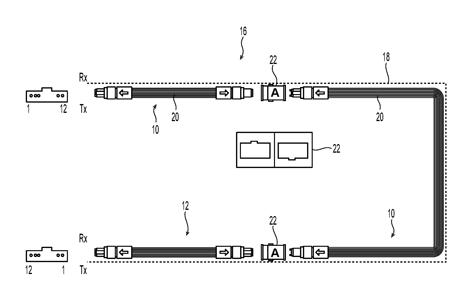
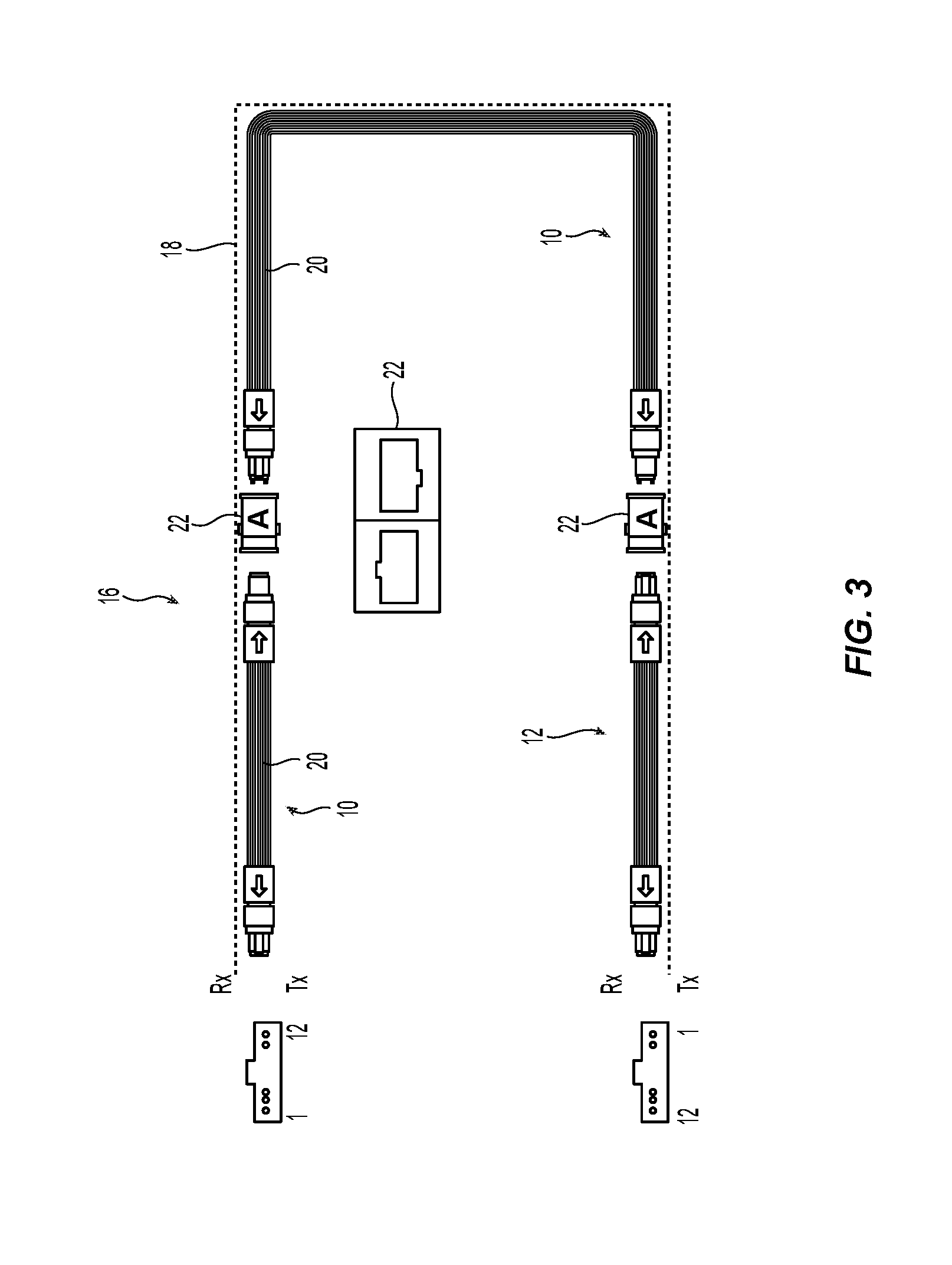
[0032] As an example, FIG. 3 illustrates a system 16 that uses an A-type connectivity system. The uncoupled ends of the fiber optic jumper cables illustrated on the left side are to be mated with a transceiver (not shown). As is known in the art, there are positions for transmitting signals (Tx) and receiving signals (Rx). It is important that the fiber optic jumper cables 10,12 are designed so that the transmit position in one of the transceivers is mated with a receive position in the other. One optical path 18 is illustrated by the solid line around the system 16. The transmit position on the bottom transceiver (at position 1) needs to reach the receive position 1 on the transceiver at the top. So, with the optical fibers 20 being all parallel to one another, there are two Type A fiber optic jumper cables and one Type B fiber optic jumper cable required to achieve that result. As illustrated in middle of the system 16, a Type A adapter 22--to join the ends of the fiber optic jumper cables--is used and the illustration shows the configuration from both ends. So the Type A adapter has one side with the key up and the other side with the key down. See also FIG. 5. Thus, if one type A and two type B fiber optic jumper cables are ordered, then the system 16 will not work. It would be better if the key at one end of the fiber optic jumper cables could be changed (or if the keys can be easily changed, then only one type of jumper needs to be ordered and they can be oriented in any fashion by the end customer).
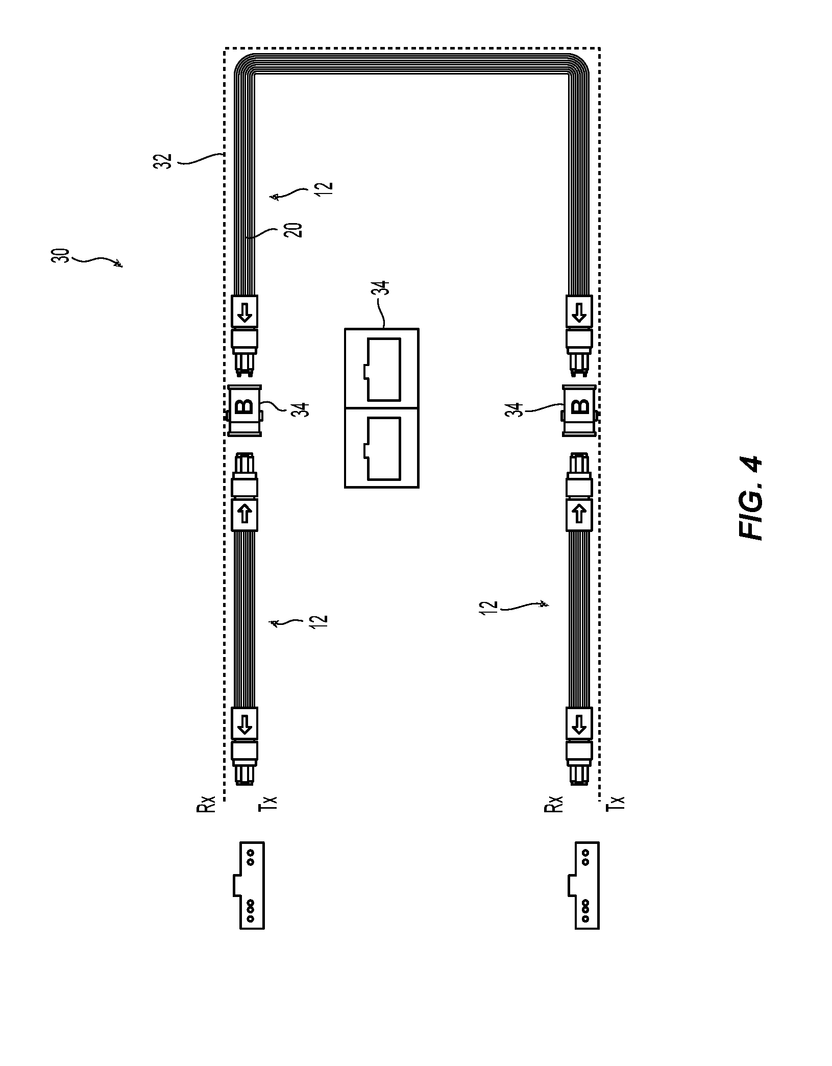
[0033] FIG. 4 illustrates a system 30 that uses a B-type connectivity system using three Type B fiber optic jumper cables. Again, the following of the optical path 32 shows the required fiber optic jumper cables 12 along with the Type B adapter 34, which mates fiber optic connectors key up to key up. See also FIG. 6. Again, if the polarity could be reversed become a significant advantages would result. Some of the prior art systems allow the removal of a key on one side and insertion on the other side, some use offset keys, and others require that at least a part outfit connect to be disassembled, and some have keys connected to the outer connector housing. All of these present significant disadvantages. Taking a fiber optic connector apart in the field has a risk of losing important parts. Not all systems use or need offset keys. And the removal of parts presents opportunities to damage the fiber optic connector, including the real danger of breaking off parts. Broken parts may not be able to be fixed and a completely new connector may have to be installed, With an increased installation time and costs. The present invention only requires a simple back-and-forth motion of a tool to achieve the desired results with little or no risk of damage or lost parts.
[0034] Referring to FIG. 7, a fiber optic connector 100 according to one embodiment of the present invention is illustrated. The fiber optic connector 100 includes a connector inner housing 102a and outer housing 102b, and a fiber optic ferrule 104. It may also include a spring 106, a spring push 108, a guide pin clamp (not shown), and guide pins 112 in guide pin holes 114. As is known in the art, the fiber optic ferrule 104 is inserted into the inner connector housing 102a and it engages a seating surface 116, which prevents the fiber optic ferrule 104 from traveling too far toward the front of the connector housing 102. The spring 106 is inserted behind the guide pin clamp, which is behind the fiber optic ferrule 104 to bias the fiber optic ferrule 104 toward the seating surface 116. A spring push 108 engages the back end of the spring 106 and the connector housing 102, securing the fiber optic ferrule 104, a spring 106, the spring push 108, and the guide pin clamp in the connector housing 102. When the fiber optic connector 100 engages another fiber optic ferrule (not shown), the fiber optic ferrules 104 of the two fiber optic connectors engage one another, causing the spring 106 to be compressed between the guide pin clamp (which engages the rear end of fiber optic ferrule 104) and the spring push 108. The fiber optic ferrule 104 is pushed rearwardly and the fiber optic ferrule 104 is unseated from the seating surface 116. As long as the spring 106 squarely engages the back end 118 of the guide pin clamp, then the fiber optic ferrule 104 can appropriately engage the other fiber optic ferrule.
[0035] The fiber optic connector 100 also includes keys 120, one on the top of the fiber optic connector 100 and one (see FIG. 10) on the bottom of the fiber optic connector 100. The keys 120 are the same (except that the keys have different colors in one embodiment to allow the orientation of the fiber optic connector to be more easily identified) for the top and the bottom of the fiber optic connector 100.
[0036] The key 120 has a front end 122 and a rear end 124. The front end 122 has a front wall 126 that protects the first latch 128. The front wall 126 also prevents a fiber optic connector from being inserted into an adapter in the wrong orientation. The front end 122 also has a greater height than the rear end 124. Extending through the length of the key 120 is an opening 130 to accommodate surfaces disposed in the recessed portions of the inner connector housing illustrated in FIG. 9. Each of the sides 132 has at the bottom a flared portion 134 the cooperates with the recessed portions of the inner connector housing 102a to create a sliding dovetail. See, e.g., FIG. 7. Alternatively, other configurations for connecting the key 120 to the inner connector housing 102a could be used.
[0037] On each of the sides 132 of the key 120 are two notches 136 spaced just behind the front wall 124. The notches 136 cooperate with a tool (see FIGS. 11-13) to allow the key 120 to be pulled from a second position to a first position, as explained more detail below. While the notches 136 are v-shaped, they could be of any appropriate shape that cooperates with the tool and allows sufficient grasping forced to pull the key 120.
[0038] In the front end 122 is a tab 140 and in the rear end 124 is a tab 142, the tabs 140, 142 are connected to the key 120 along one side 144, 146. This arrangement allows the tabs 140, 142 to flex both upward and downward, i.e., into the opening 130 and upwards away from the opening 130 for reasons that will be identified below. Attached at the free end of each of the tabs 140, 142 are latches 128, 148, respectively. The latch 128 is a first latch that retains the key 120 in the first position and the second latch 148 retains the key 120 in the fiber optic connector 100 by preventing the key 120 from being removed. As will be made clear below, once the key 120 is disposed within the fiber optic connector 100, it cannot be removed without completely removing the outer housing 102b. Since the outer housing 102b is not intended to be removed once it is installed (and without damaging the fiber optic connector), the keys 120 are permanently installed in the fiber optic connector 100.
[0039] One version of an inner connector housing 102a according to an embodiment of the present invention is illustrated in FIG. 9. The inner connector housing is typical for an MTP connector except for two features. The first are the recessed portions 160 (one on the top and one on the bottom, both being the same) to receive the key 120. The second feature, which is not related to the present application but is different from a standard MTP inner connector housing are the openings 162, which allow for access to a pin keeper that allows the gender of the fiber optic ferrule to be changed. Co-pending application Ser. No. 15/247,839, the contents of which are incorporated herein by reference, describes one such pin keeper and is assigned to the same applicant as the present application. A second application of this applicant, having attorney docket number USCO-070 and being filed on the same day as the present application, discloses a second such pin keeper. The contents of the second application are also incorporated herein by reference.
[0040] The recessed portions 160 extend from a front end 164 of the inner connecting housing 102a, without a front barrier to the recessed portions 160. Such a configuration allows for the key 120 to be slid into the recessed portion from in front of the inner connector housing 102a. The recessed portion has a central portion 166 and then an outer flared portion 168 that corresponds to the flared portion 134. The recessed portion runs a substantial portion of the length of the inner connector housing 102a--not quite twice the length of the key 120. See, e.g., FIG. 11. At the distal end 170 of the recessed portion 160 is a rear wall 172 to provide a stop for the key 120.
[0041] Applicant notes that the term "front" or "forward" means that direction where the fiber optic connector would meet with another fiber-optic connector or device, while the term "rear" or "rearward" is used to mean the direction from which the optical fibers enter into the fiber-optic ferrule or fiber optic connector. Thus, "front" is that part of the inner connector housing 102a closest to the legend "FIG. 9" and "forward" is out and downward from the page. See also FIG. 7. "Rear" is that part of the inner connector housing 102a that is on the top of the page and "rearward" is up and into the page.
[0042] Disposed within the recessed portion 160 is a raised center member 180. The raised center member 180 has a forward facing surface 182 and a rearward facing surface 184. The raised center member 180 is configured to pass through the opening 130 in the key 120. The raised center member 180 and its particular location within the recessed portion 160 is also instrumental in the positioning of the key 120 in the first and second positions. There is also an indentation 186 in the raised center member 180 to receive the first latch 128. The raised center member 180 could also be comprised of multiple smaller sections if so desired. The raised center member 180 provides the forward facing and rearward facing services, which could be done in alternative ways and still fall within the scope of the present invention.
[0043] Turning to FIG. 10, a cross sectional view along a longitudinal axis of the inner connector housing 102a and two keys 120 are illustrated. The other components of fiber optic connector 100 have been removed from the remaining figures for clarity purposes only. On the top of the inner connector housing 102a is a first key 120t while a second key 120b is disposed on the bottom of connector housing 102a. Key 120t is in a first position--or the position that will determine the orientation of the fiber optic connector 100. The second key 120b is in the second position, or a retracted position that does not affect the orientation of the fiber optic connector 100.
[0044] The key 120t is slid into the recessed portion 160 so that the flared portion 134 engages the corresponding outer flared portion 168 to keep the key 120t within the fiber optic connector 100. The second latch 148, by virtue of latching surface facing forward and also having a chamfered leading edge (as the key 120t is pushed onto the inner connector housing 102a) and because it is on the flexible tab 142, slides over the raised center portion 180 and past the rearward facing surface 184. The second latch 148 would be hidden from view (and access) by the outer connector housing 102b. See FIG. 7. At this point, the key 120t is prevented from traveling any farther rearwardly as the front latch 128 engages the forward facing surface 182. With the front latch 128 protected by the front wall 126, it is very difficult, if not impossible, for the front latch 128 to be moved unintentionally and without an appropriate tool to do so. Thus, insertion of a fiber optic connector into an adapter or other device with an incorrect orientation would be impossible with the key 120t in place as illustrated in FIG. 10. The key 120t also cannot be pulled out of the inner connector housing 102a because the second latch 148 engages the rearward facing surface 184.
[0045] In viewing FIG. 10, the inner housing could be rotated 180 degrees so that the top is the bottom and the bottom is the top, but for the purposes of the discussion herein, the features remain the same regardless of the orientation.
[0046] Key 120b is in the second position on the bottom of the inner connector housing 102a. Key 120b would preferably be placed in the second position before the fiber optic connector is assembled. However, it is possible, as discussed below with regard to the changing of polarity, to add both keys after the inner and outer connector housings are in place.
[0047] Key 120b has the first latch 128 in the indentation 186 in the raised center member 180 and the rear end 124 engaging the rear wall 172 at distal end 170. With the first latch 128 in the indentation 186, the key 120b will not be able to move within the fiber optic connector 100, without using a tool to move it.
[0048] The tool 200 that is used to move one of the keys 120 rearward and one forward in a single action is illustrated in FIGS. 11-13. The tool 200 has a first side 202 that is aligned with the key 120 disposed in the first position. Thus, the second side 204 of tool 200 is aligned with the side of the fiber optic connector 100 with the key 120 in the second position. If the tool 200 is aligned incorrectly (second side 204 aligned with the key 120 in the first position), the tool 200 will not be able to move the key 120 as the latch 128 will prevent the key 120 from moving, thereby signaling to the user that the tool 200 needs to be reoriented with respect to the fiber optic connector 100.
[0049] The first side 202 of the tool 200 has a leading prong 206 with a chamfered edge 208 at a first end 210. On either side of the leading prong are two side extensions 212, preferably with flat leading edges 214, that engage the front wall 126 of the key 120. Referring to FIGS. 14 and 15, the tool 200 is inserted around the inner connecting housing 102a and the chamfered edge 208 of the leading prong 206 engages the first latch 128. See FIG. 15. This causes the first latch 128 to be lifted up and clear the forward facing surface 182. Then as the tool 200 is inserted farther, the two side extensions 212 engage the front wall 126 and the key 120t is pushed rearwardly toward the rear wall 172. Once the rear end 124 engages the rear wall 172, the tool 200 can not be pushed any farther into the fiber optic connector 100. This position is illustrated in FIG. 16. In the top left detail of FIG. 16, the first latch 128 is disposed in the indentation 186, while in the top right detail of FIG. 16 the rear end 124 is disposed against the rear wall 172. At this point, it should be noted that both keys 120t and 120b are in the second position. However, the tool 200 is disposed as far into the fiber optic connector 100 as possible. The top key 120t will remain in this second position when the tool 200 is extracted. Nothing on the tool 200 engages the top key 120t such that pulling the tool 200 out will cause the top key 120t to come with it. Moreover, the first latch 128 is disposed within the indentation 186 which supplies resistance to removal of the top key 120t.
[0050] Returning to the installation of the keys 120 after the inner and outer connector housings 102a,102b have been installed, one key 120b (again, the bottom reference merely indicates that the key will in this explanation will be in the second position), will be inserted into the recessed portion 160 as noted above. It can be pushed back into the inner connector housing 102a, with or without the aid of the tool 200, until the first latch 128 engages the forward facing surface 182. The tool 200 then will be used as noted above to push the key 120b deeper into the recessed portion 160--until it engages the rear wall 172. Without a key 120 on the other side of the fiber optic connector 100, the tool 200 will simply slide out, leaving the key 120b in the second position. A second key 120t (again because it will be in the first position) would be inserted into the opposite side of the fiber optic connector 100 with or without the use of the tool 200 until the first latch 128 engages the forward facing surface 182. Now there are two keys 120 installed in the fiber optic connector 100. Alternatively, the keys 120 may also be installed from the back side of the inner connector housing 102a before outer connector housing 102b is installed.
[0051] Returning to FIGS. 11-13, these figures are used to describe the second side 204 of the tool and moving the key 120b from the second position to the first position. The second side 204 of the tool 200 has two tabs 216 at the first end 210. Each of the tabs 216 has a protrusion 218 on an inside portion of the tabs 216 and therefore the protrusions 218 face each other. The protrusions 218 have a v-shape that correspond to the notches 136 on the front end 122 of the keys 120. It is the engagement of the protrusions 218 with the notches 136 that allows the tool 200 to move the key 120b from the second position to the first position. This will be explained with reference to FIGS. 17 and 18. In FIG. 17, the tool 200 is inserted as far as possible after moving key 120t from the first position to the second position. At this location, the tabs 216 have passed by the front end 122 of the key 120b and the protrusions 218 have engaged the notches 136. See FIG. 18, which shows one side of the tool 200 engaging the key 120b and, in particular, the tab 216 and protrusion 218 in the notch 136. The force of the tool 200 on the front end 122 of the key 120b in the notches 136 is greater than the force required to move the first latch 128 out of the indentation 186 in the recessed portion 160. As the tool 200 is pulled out of the fiber optic connector 100, the key 120b is moved with the tool 200. See FIG. 19. The second latch 148 will then engage the rearward facing surface 184, preventing any further forward movement of the key 120b. As the tool is continued to be pulled, the tabs 216 will flex open allowing the key 120b to be freed from the tool 200. At this point, the first latch 128 will be in front of the forward facing surface 182 and the key 120b is now in the first position. As noted above, the key 120t is left in the second position and the two keys 120 have been reversed in position within the fiber optic connector 100. See FIG. 20.
[0052] It will be apparent to those skilled in the art that various modifications and variations can be made to the present invention without departing from the spirit and variations of this invention provided they come within the scope of the appended claims and their equivalents.
* * * * *
D00000
D00001
D00002
D00003
D00004
D00005
D00006
D00007
D00008
D00009
D00010
D00011
D00012
D00013
D00014
D00015
D00016

D00017
XML
uspto.report is an independent third-party trademark research tool that is not affiliated, endorsed, or sponsored by the United States Patent and Trademark Office (USPTO) or any other governmental organization. The information provided by uspto.report is based on publicly available data at the time of writing and is intended for informational purposes only.
While we strive to provide accurate and up-to-date information, we do not guarantee the accuracy, completeness, reliability, or suitability of the information displayed on this site. The use of this site is at your own risk. Any reliance you place on such information is therefore strictly at your own risk.
All official trademark data, including owner information, should be verified by visiting the official USPTO website at www.uspto.gov. This site is not intended to replace professional legal advice and should not be used as a substitute for consulting with a legal professional who is knowledgeable about trademark law.