Ammunition with Energy Absorbing Features
Moshenrose; Paul ; et al.
U.S. patent application number 16/103667 was filed with the patent office on 2019-02-14 for ammunition with energy absorbing features. This patent application is currently assigned to MAC LLC. The applicant listed for this patent is MAC LLC. Invention is credited to Nikica Maljkovic, Paul Moshenrose.
| Application Number | 20190049223 16/103667 |
| Document ID | / |
| Family ID | 65274866 |
| Filed Date | 2019-02-14 |


| United States Patent Application | 20190049223 |
| Kind Code | A1 |
| Moshenrose; Paul ; et al. | February 14, 2019 |
Ammunition with Energy Absorbing Features
Abstract
A multi-piece ammunition article that has a base portion configured to support the majority of the stress load during firing and a caselet portion that is configured to support the firing loads. Furthermore, the caselet portion has a weakened surface with increased compliance which aids in the storage and firing of the ammunition.
| Inventors: | Moshenrose; Paul; (Bay St. Louis, MS) ; Maljkovic; Nikica; (New Orleans, LA) | ||||||||||
| Applicant: |
|
||||||||||
|---|---|---|---|---|---|---|---|---|---|---|---|
| Assignee: | MAC LLC Bay St. Louis MS |
||||||||||
| Family ID: | 65274866 | ||||||||||
| Appl. No.: | 16/103667 | ||||||||||
| Filed: | August 14, 2018 |
Related U.S. Patent Documents
| Application Number | Filing Date | Patent Number | ||
|---|---|---|---|---|
| 62545263 | Aug 14, 2017 | |||
| Current U.S. Class: | 1/1 |
| Current CPC Class: | F42B 33/001 20130101; F42B 5/307 20130101 |
| International Class: | F42B 5/307 20060101 F42B005/307; F42B 33/00 20060101 F42B033/00 |
Claims
1. A multi-piece ammunition article comprising: A base having a first end and a second end wherein the first end is configured to receive a primer and wherein the second end is open and is configured to cooperatively engage with a caselet; the caselet portion further comprises an elongated body with an outer surface and defining an inner cavity wherein the caselet further comprises a base end and a projectile end, wherein the base end is oppositely configured to cooperatively engage with the open end of the base portion such that an overlap region is formed thereby forming a smooth transition between the base portion and the caselet portion, and wherein the outer surface of the caselet portion is configured with a contoured surface such that the outer surface is configured to be uneven.
2. The ammunition article of claim 1 wherein the contoured outer surface is defined by a pattern selected from a group consisting of radial grooves, vertical grooves, diagonal grooves axial rows and intermittent depressions.
3. The ammunition article of claim 1 wherein the contoured outer surface comprises a plurality of independent structures thereby modifying the outer surface to reduce the strength thereof.
4. The ammunition article of claim 1 wherein the caselet portion is a polymeric material.
5. The ammunition article of claim 4 wherein the caselet portion comprises a first polymeric region and a second polymeric region, and wherein the first polymeric region is configured to cooperatively engage with the base portion and the second polymeric region is configured to cover at least a portion of the first polymeric region.
6. The ammunition article of claim 1 further comprising an over mold disposed such that it covers at least a portion of the caselet.
7. The ammunition article of claim 1 the article is configured to accommodate a caliber projectile selected from the group consisting of .22, .22-250, .221, .223, .243, .25-06, .264 USA, .277 USA, .270, .300, .30-30, .30-40, 30.06, .303, .308, .357, .38, .40, .44, .45, .45-70, .50 BMG, 500 Nitro, 5.45 mm, 5.56 mm, 6.5 mm, 6.8 mm, 7 mm, 7.62 mm, 8 mm, 9 mm, 10 mm, 12.7 mm, 14.5 mm, 20 mm, 25 mm, 30 mm, 40 mm and wildcat.
8. The ammunition article of claim 3 wherein the independent structures are selected from a group consisting of amorphous shapes and geometric shapes.
9. The ammunition article of claim 6 wherein the over mold further comprises a corresponding contoured surface to that of the outer surface of the caselet.
10. The ammunition article of claim 2 wherein the caselet has an overall contact surface area in contact with a chamber of a weapon and such contact surface area is reduced by 10%.
11. The ammunition article of claim 2 wherein the axial rows have a semicircular cross section.
12. The ammunition article of claim 2 wherein the intermittent depressions have a semicircular cross section.
13. The ammunition article of claim 6 wherein the overmold comprises an elastomeric material.
14. A method for producing a multi-piece ammunition article comprising: Having a base portion having a first end and a second end wherein the first end is configured to receive a primer and wherein the second end is open and is configured to cooperatively engage with a caselet Having a caselet portion further comprising an elongated body with an outer surface and defining an inner cavity wherein the caselet portion further comprises a base end and a projectile end, wherein the base end is oppositely configured to cooperatively engage with the open end of the base portion such that an overlap region is formed thereby forming a smooth transition between the base portion and the caselet portion; Joining the base portion and the caselet portion; and Filling the article with a propellant.
15. The method for producing a multi-piece ammunition article of claim 14 wherein the base portion and the caselet portion are joined from a process selected from a group consisting of molding, mechanical interference, ultrasonic welding, adhesive, and heat crimping.
16. The method for producing a multi-piece ammunition article of claim 14 further comprising: Obtaining a projectile; and Securing the projectile in the projectile end of the caselet portion.
17. The method for producing a multi-piece ammunition article of claim 16 wherein the projectile is secured from a process selected from a group consisting of molding, mechanical interference, ultrasonic welding, adhesive, and heat crimping.
Description
CROSS-REFERENCED APPLICATIONS
[0001] This application claims priority to U.S. Provisional Patent Application No. 62/545,263 filed on Aug. 14, 2017, the disclosure of which is herein incorporated by reference in its entirety.
FIELD OF THE INVENTION
[0002] The present invention relates to ammunition articles, and, more particularly, to ammunition cartridge casings, where a portion of the ammunition casing is selectively weakened in order to modify its response during cycling in the weapon.
BACKGROUND OF THE INVENTION
[0003] The nature of ammunition articles illustrates the need for materials used in the manufacture thereof to demonstrate excellent mechanical and thermal properties. This is especially true for high pressure rifle and machine gun ammunition. As a result, prevalent materials for production of cartridge cases for all calibers of ammunition in the world today are metals. However, the various metals used in the manufacture of ammunition articles include various disadvantages including increased cost of production, viability for long term storage, and the inability to withstand the higher pressures of some calibers of ammunitions.
[0004] Given these issues, desirable materials for ammunition cartridge casing fabrication would be lighter in weight, less costly and have mechanical properties suitable for use in ammunition applications.
[0005] Despite many efforts at making the ammunition casings lighter, the success has proven elusive. A solution is needed which would allow usage of lightweight materials such polymer components. Specifically, the solution for usage of polymer components must address their inferior mechanical and thermal properties.
BRIEF SUMMARY OF THE INVENTION
[0006] This application is directed to a multi-piece ammunition article that is configured with a base portion designed to support the majority of the stress load during firing and a caselet portion that is designed to handle the firing loads and has at least one layer. Furthermore, many embodiments have a caselet portion with a weakened surface structure that increases the overall compliance of the article which aids in the storing and firing of the ammunition article.
[0007] Many embodiments of the article include a base with a first end and a second end wherein the first end is configured to receive a primer and wherein the second end is open and is configured to cooperatively engage with a caselet. The caselet portion further has an elongated body with an outer surface and defines an inner cavity. The caselet portion is configured to have a base end and a projectile end. The base end is oppositely configured to cooperatively engage with the open end of the base portion such that an overlap region is formed thereby forming a smooth transition between the base portion and the caselet portion. Furthermore, the outer surface of the caselet portion is configured with a contoured surface such that the outer surface is configured to be uneven.
[0008] In other embodiments, the contoured outer surface is defined by a pattern selected from a group consisting of radial grooves, vertical grooves, diagonal grooves axial rows and intermittent depressions.
[0009] In still other embodiments, the contoured outer surface comprises a plurality of independent structures thereby modifying the outer surface to reduce the strength thereof.
[0010] In yet other embodiments, the caselet portion is a polymeric material.
[0011] In still yet other embodiments, the caselet portion is defined by a first polymeric region and a second polymeric region. The first polymeric region is configured to cooperatively engage with the base portion and the second polymeric region is configured to cover at least a portion of the first polymeric region.
[0012] In other embodiments, the article has an over mold disposed such that it covers at least a portion of the caselet.
[0013] In still other embodiments, the article is configured to accommodate a caliber projectile selected from the group consisting of .22, .22-250, .221, .223, .243, .25-06, .264 USA, .277 USA, .270, .300, .30-30, .30-40, 30.06, .303, .308, .357, .38, .40, .44, .45, .45-70, .50 BMG, 500 Nitro, 5.45 mm, 5.56 mm, 6.5 mm, 6.8 mm, 7 mm, 7.62 mm, 8 mm, 9 mm, 10 mm, 12.7 mm, 14.5 mm, 20 mm, 25 mm, 30 mm, 40 mm and wildcat.
[0014] In yet other embodiments, the independent structures are selected from a group consisting of amorphous shapes and geometric shapes.
[0015] In still yet other embodiments, the over mold has a corresponding contoured surface to that of the outer surface of the caselet.
[0016] In other embodiments, the caselet has an overall contact surface area in contact with a chamber of a weapon and such contact surface area is reduced by 10%.
[0017] In yet other embodiments, the caselet has an overall chamber contact surface area that is reduced by at least 5%.
[0018] In still other embodiments, the axial rows have a semicircular cross section.
[0019] In still yet other embodiments, the intermittent depressions have a semicircular cross section.
[0020] In other embodiments, the overmold comprises an elastomeric material.
[0021] Many other embodiments include a method for producing a multi-piece ammunition article where an ammunition article as described in the many embodiments herein is selected and the caselet and base portion are joined to form a casing that may be subsequently filled with a propellant.
[0022] In other embodiments, the method includes the process by which the base portion and the caselet portion are joined from a process selected from a group consisting of molding, mechanical interference, ultrasonic welding, adhesive, and heat crimping.
[0023] In still other embodiments the method includes obtaining and securing a projectile to the projectile end of the caselet portion.
[0024] In yet other embodiments, the projectile is secured from a process selected from a group consisting of molding, mechanical interference, ultrasonic welding, adhesive, and heat crimping.
[0025] Additional embodiments and features are set forth in part in the description that follows, and in part will become apparent to those skilled in the art upon examination of the specification or may be learned by the practice of the disclosure. A further understanding of the nature and advantages of the present disclosure may be realized by reference to the remaining portions of the specification and the drawings, which forms a part of this disclosure.
BRIEF DESCRIPTION OF THE DRAWINGS
[0026] The description will be more fully understood with reference to the following figures, which are presented as exemplary embodiments of the invention and should not be construed as a complete recitation of the scope of the invention wherein:
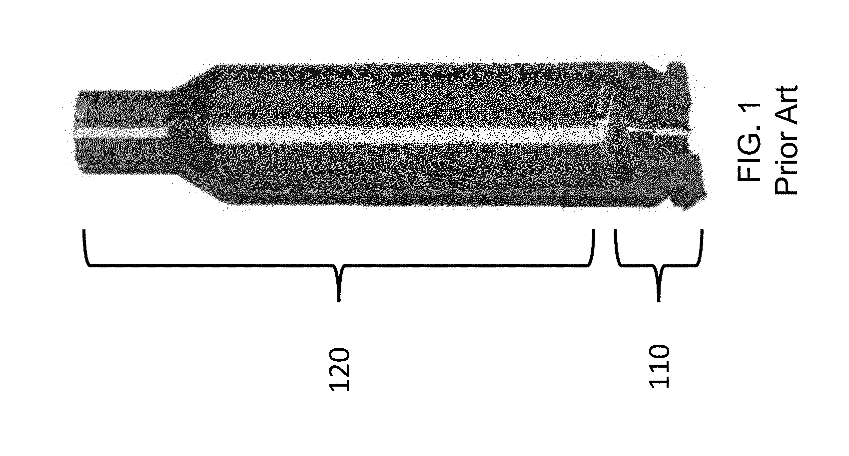
[0027] FIG. 1 illustrates a cross sectional view of an ammunition article in accordance with the present art.
[0028] FIG. 2 illustrates a cross sectional view of an ammunition article in accordance with embodiments.
[0029] FIG. 3 illustrates an isometric view of an ammunition article having radial ribs in accordance with many embodiments.
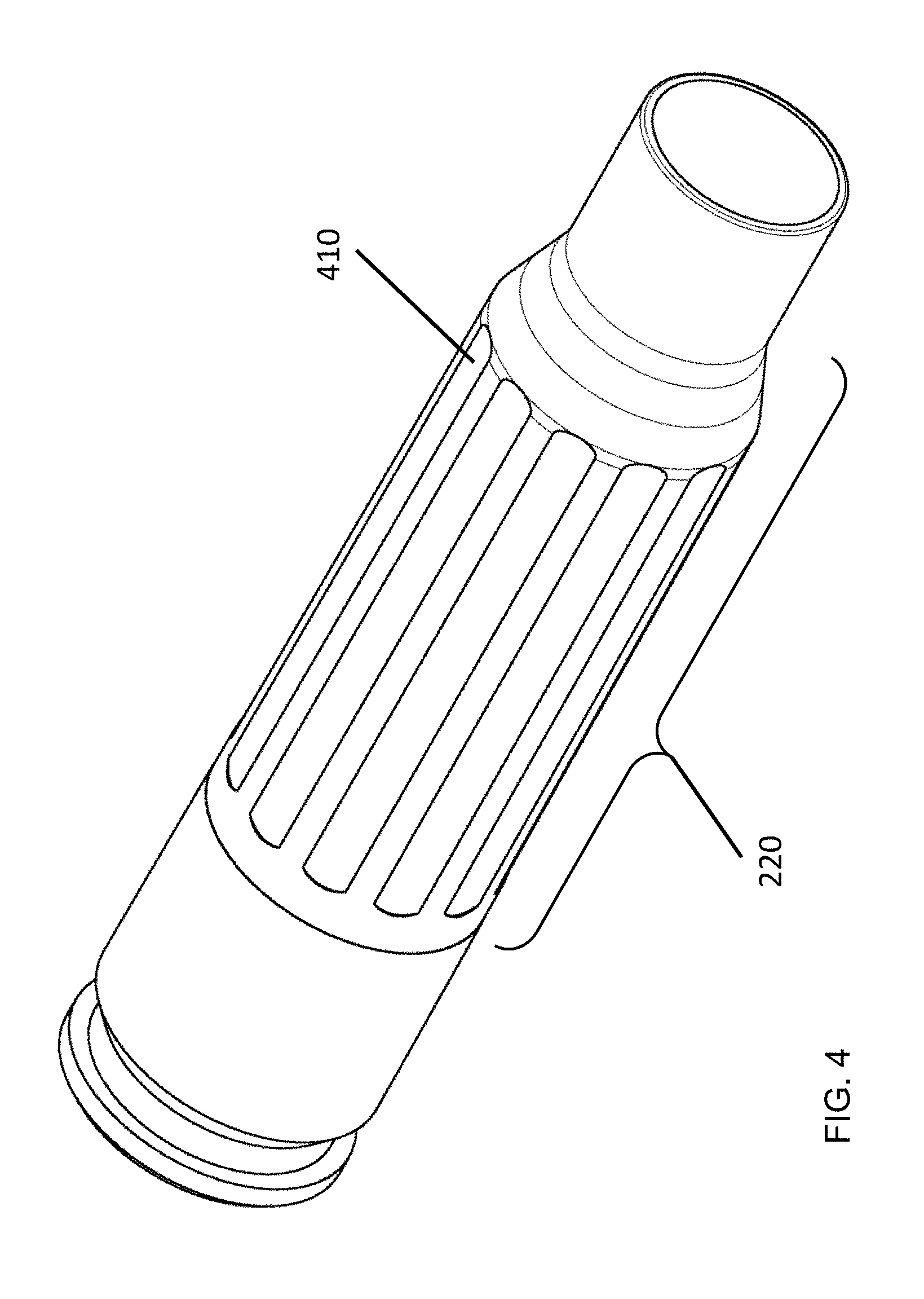
[0030] FIG. 4 illustrates an isometric view of an article having axial rows according to various embodiments.
[0031] FIG. 5 illustrates an isometric view of an article having various depressions in the body according to various embodiments.
[0032] FIG. 6 illustrates an exemplary embodiment having multiple caselet portions.
DETAILED DESCRIPTION OF THE INVENTION
[0033] Described herein is an ammunition article that is an improvement over the traditional articles, wherein preference is given to a design of an article that reduces cost and maintains the mechanical and thermal properties desired in the use of ammunition articles. In accordance with many embodiments the present invention describes an ammunition article having a multi-piece configuration in which a portion of the article is metallic while another portion is formed of a polymeric type material having a weakened contoured surface to aid in storage and use of the article.
[0034] For the purposes of the present invention, the term "ammunition article" as used herein refers to a complete, assembled round of ammunition that is ready to be loaded into a firearm and fired. An ammunition article may be a live round fitted with a projectile, or a blank round with no projectile. An ammunition article may be any caliber of pistol or rifle ammunition and may also be other types such as non-lethal rounds, rounds containing rubber bullets, rounds containing multiple projectiles (shot), and rounds containing projectiles other than bullets such as fluid-filled canisters and capsules
[0035] An ammunition casing is a portion of the ammunition article that physically holds propellant, primer and projectile (if present). Thus, the ammunition casing is the portion of an ammunition article that remains after firing and is extracted out of the weapon.
[0036] In the United States brass is the leading material, followed in smaller amounts by steel (especially in countries associated with former Soviet Union) and, in very limited applications, aluminum. The use of lightweight materials for ammunition cartridge cases has been extensively investigated over the past 40 years, but success has been elusive.
[0037] Brass cases (specific gravity .about.8.3) suffer from a number of disadvantages, the most important of which is heavy weight and high cost. Given very high costs of copper in recent years, a need exists for a lower cost alternative to brass ammunition casings.
[0038] Steel (SPGR .about.7.9) cases have been used extensively in countries of the former Eastern Block countries as the main material for their rifle and machine gun ammunition. Steel offers many advantages over brass--it is significantly less expensive and its price volatility is lower, it offers a greater range of achievable mechanical properties and it is slightly (on the order of 5%) lighter.
[0039] Steel and other ferrous cases, however, also have a series of disadvantages such as decreased corrosion resistance and inability to obturate as efficiently as brass cases. Obturation refers to the ability of the case to efficiently seal the chamber and focus all of the energy and combustion gases forward in the process of propelling the projectile through the weapon barrel. Steel traditionally has been inferior to brass in this area and it is related to a differing elastic limit between brass and steel. The most significant downside to steel cases, however, is that steel is only marginally lighter than brass and thus so far steel cases have offered only minor weight savings.
[0040] Aluminum (SPGR .about.2.7) has a very serious disadvantage of potential explosive oxidative degradation and is thus used only in low-pressure cartridges or in applications that can tolerate relatively thick casing walls (for example pistol, medium caliber and low pressure grenade ammunition). As a result of this characteristic aluminum has not typically been used in ammunition for rifles or machine guns. It would be of great benefit in reducing the weight carried if a solution could be found that could successfully utilize aluminum in rifle or machine gun ammunition design. Other lightweight non-ferrous materials (ex. Magnesium, lithium) have broadly the same issues.
[0041] Many lightweight polymeric materials (SPGR 0.8-4.0) have been investigated; however, to date, polymers have been used only in niche ammunition applications where their inferior mechanical and thermal properties can be tolerated (e.g., shotgun shells contain polyethylene components). There has been a wealth of work on polymer case. Some of the most relevant work can be found in US Patent Application US 2006/0207464 A1, incorporated herein by reference.
[0042] While stability under broad ranges of handling and storage conditions are crucial, the greatest mechanical demands on the cartridge material are experienced during the firing event. The material at the cartridge base end, which supports the primer, must first absorb the impact of a firing pin on the primer without mechanical failure. Upon ignition and combustion of an encapsulated propellant, rapidly expanding gases create high pressure, which expels a projectile from the barrel of the firearm. The ammunition cartridge casing must withstand and contain the pressure developed by the explosion so that the gaseous combustion products expand only in the direction of the barrel opening, thus maximizing energy conversion to projectile kinetic energy. The peak chamber pressures in typical rifle and machine gun ammunition range from 35,000 to 70,000 psi and produce projectile velocities in a range of 1,000-4,000 feet per second.
[0043] A firearm's cartridge chamber closely fits the outside of a cartridge and thus supports the majority of the cartridge casing wall in the radial direction; however, in many firearms, a portion of the cartridge base end protrudes from the chamber and is thus unsupported. During firing, a stress profile is developed along the cartridge casing, with the greatest stresses being concentrated at the base end. This base end is also called the "head" of the cartridge. Therefore, the cartridge head must possess the greatest mechanical strength, while a gradual decrease in material strength is acceptable axially along the casing toward the end that receives the projectile. As a result of these requirements, the head is typically the thickest and heaviest portion of the casing. This can be illustrated in FIG. 1 where it can be seen that the head 110 is thicker than the remaining portions of the casing.
[0044] A typical brass cartridge casing is engineered to provide a strength profile along the casing length, which reflects the varying mechanical demands, with the strongest and hardest material located at the cartridge base end 110. In metals, a strength profile is easily induced by varying the heat treatment conditions from one end of the casing to the other, but this is not an option for polymers. A mechanical strength profile can be achieved in a polymeric ammunition cartridge casing by varying the casing wall thickness, but, since the casing external geometry is fixed by existing firearm chamber size, an increased casing wall thickness often results in a cavity with insufficient internal volume to accept the required propellant charge.
[0045] While the most severe mechanical requirements of an ammunition cartridge are focused on the head portion 110, the top portion 120 of the casing must meet several material requirements as well. Upon combustion of the cartridge propellant, a very large quantity of energy is released in a matter of a few milliseconds, thus producing very high stresses and strain rates. The casing material must possess adequate ductility to absorb the shock of the explosion without experiencing brittle fracture. Also, the material must possess sufficient rigidity and strength to avoid creep or flow when multiple ammunition articles are fired in rapid succession. Finally, the ammunition casing must relax sufficiently and shrink away from the chamber wall in order to allow facile extraction of the spent round.
[0046] A more detailed description of the various embodiments of the invention is illustrated herein. Turning to FIG. 2, an embodiment of the present invention is thus illustrated. Shown in FIG. 2 is an ammunition article in accordance with various embodiments in which the head portion is a metallic cap 210. The metallic cap portion 210 is joined to a polymeric caselet portion 220.
[0047] Although many methods are known for attaching the cap and caselet portions of an ammunition cartridge casing, any method of attaching the caselet and cap is acceptable provided that the two components are joined securely and that gaseous combustion products are not allowed to escape through the assembled casing upon firing. Many embodiments may include securing methods such as mechanical interlocking (i.e., ribs and/or threads), adhesives, molding in place, heat crimping, ultrasonic welding, friction welding etc. These and other suitable methods for securing individual pieces of a two-piece or multi-piece cartridge casing are useful in the practice of the present invention.
[0048] In accordance with many embodiments, the polymeric caselet portion 220 is designed to meet the design requirements described above; in that it is capable of handling the mechanical and thermal demands of that portion of the article during storage and, more importantly, the firing process. The cap 210 may be configured to house a live primer in a primer housing portion 230 of the cap. Additionally, the cap 210 is joined securely to the caselet portion 220 via a smooth transition 240 that forms a smooth interior cavity 250 of the article.
[0049] In accordance with many embodiments the transition portion 240 may be configured to overlap such that the polymeric portion of the casing is designed to overlap the inside diameter of the cap portion 210. The cap portion 210 may be configured such that the inside diameter is smaller in the transition area thereby integrally accommodating the end of the polymeric portion 220 to form a smooth transition region 240 on both the outside and inside of the casing. A propellant charge may be introduced into the interior cavity formed by the assembled casing. A projectile may then be inserted into the open caselet end 260 and secured with an adhesive.
[0050] Other exemplary embodiments of methods for securing the projectile into the open end of a caselet are as follows: [0051] 1. forming the caselet by molding the polymeric material of the caselet around at least a portion of the projectile; [0052] 2. securing the projectile to the caselet by mechanical interference; [0053] 3. securing the projectile to the caselet by ultrasonic welding. [0054] 4. securing the projectile to the caselet by a combination of molding in place and use of an adhesive; and [0055] 5. securing the projectile to the caselet by heat crimping the caselet around the projectile.
[0056] The assembled ammunition article may then be loaded into a firearm chamber and fired.
[0057] It is preferable, according to various embodiments, that a portion of the caselet 200 may have areas of reduced material or reduced strength along the casing. The reduction of material may be through the use of vertical, diagonal or radial ribs; some of such embodiments are illustrated further in FIGS. 3-7. Other embodiments may include a faceted design, an elastomeric over mold or some other flexible design solution with reduced strength but increased compliance.
[0058] The reduction of material according to various embodiments may be illustrated in FIG. 3 by way of the grooves 310 in the caselet portion of the casing. As previously discussed the removed sections 310 may take on any form that is desirable for manufacturing. Such as for example the groove may be in the form a ribs that have been molded into the casing surface or they may be machined later. The grooves 310 may also be radial ribs that encompass the casing. In other embodiments the grooves 310 may take on the form of continuous or incongruent surface features such as amorphous bumps or any defined geometric shape. Additionally, the casing may, as discussed previously, be adapted with an elastomeric over mold. The over mold, in many embodiments may also be configured with individual shapes or may be configured to match the surface of the pre-shaped casing. Other embodiments may include additional layers of over molded or even under molded elastomeric, thermoset, thermoplastic, or metallic that may be configured with geometric features similar to those discussed above.
[0059] Such designs are preferable to enhance the survival of the case. The result of the preferable design allows for greater elongation and increased longevity of the casing despite the underlying hydrostatic stress of the system. Additionally, similar designs help to better facilitate the insertion and removal of the case from any particular firearm. A similar approach may be used for single or multi-pieced casings where the number of components is greater than two. For example, a three piece casings may incorporate a bottom cap and two separate components for caselet.
[0060] In accordance with other embodiments, FIG. 4 illustrates an embodiment where the caselet is weakened by removing portions of the external surface in axial rows 410, resulting in a faceted surface. In many such embodiments, the axial rows 410 may have a cross section in the form of a semicircle, however, any such cross section may be suitable. Such embodiments illustrate a caselet having a pencil-like appearance. The depth and width of the facets can be of any configuration as long as the overall functionality of the casing is not compromised by the design. In some embodiments the caselet may have a minimum of 10% reduction in caselet surface area contacting the weapon chamber. Other embodiments may have a smaller reduction in caselet surface area contacting the weapon chamber while still other embodiments may have more than 10% reduction in caselet contact surface area.
[0061] Similarly, to embodiments described above, faceted surface increases compliance response of the caselet to impacts on the weapon frame and assists in ejection. Additionally, faceted surface may reduce the overall friction with the weapon chamber. This, in turn, reduces the overall acceleration and ultimate speed of the ejection process, further improving the ejection characteristics of the polymeric lightweight ammunition.
[0062] In accordance with other embodiments the caselet may be weakened by removing intermittent portions of the external surface, resulting in intermittently placed depressions 510 in the surface thereof. In many such embodiments, the intermittent depressions 510 may have a cross section of a semicircle or a concave like depression. Such embodiments may give the caselet a golf ball-like appearance. Although not illustrated, other embodiments may include raised portions rather than depressions that produce a similar effect as the intermittent depressions 510. The size i.e., depth or height and width of these surface features can be of any configuration as long as the overall caselet has a minimum of 10% reduction in caselet surface area contacting the weapon chamber. Similarly, to embodiments described above, golf-ball-like surface increases compliance response of the caselet to impacts on the weapon frame and assists in ejection. Additionally, golf-ball-like surface may reduce the overall friction with the weapon chamber. This, in turn, reduces the overall acceleration and ultimate speed of the ejection process, further improving the ejection characteristics of the polymeric lightweight ammunition. Although a specific type of depression is illustrated, it should be understood that any type of intermittent depression may be suitable.
[0063] As previously discussed, many embodiments of a multi-piece casing may include three or more portions; one being the cap and two or more portions making up the caselet portion. For example, FIG. 6 illustrates an embodiment of a multi-piece ammunition article having two different portions of the caselet. Similar to the article illustrated in FIGS. 2 through 5, FIG. 6 comprises a metallic cap portion 210 adjoined to a first polymeric portion 610. In a similar fashion as described previously, the first polymeric portion 610 is connected to the metallic cap portion 210. Subsequently, the casing comprises a second polymeric portion 620 that may overlay a portion of the first polymeric portion 610. In some embodiments the second polymeric portion 620 may also be configured with the any of the surface features described herein such as the grooves 310, axial rows 410, and/or intermittent depressions 510. In any number of configurations of polymeric layers, it is preferable that many embodiments may be configured such that the strength may be reduced and the compliance increased through surface features as discussed herein.
[0064] Typical materials used for the overmolding a polymeric portion are elastomeric or highly damping materials. These are typically lower in strength than polymeric materials that may be used for the rest of the caselet 220, and thus lower the overall rigidity and strength of the caselet. This results in increased compliance of the case and improves ejection in certain types of weapons. For example, improvements in ejection can be noted for weapons such as the MK48 and M240 machine guns.
[0065] As previously discussed the casing is where the primer, propellant, and projectile are stored and is what remains after the firing of a round through the firearm of choice. The external dimensions of the assembled casing are largely guided by the weapon chamber dimensions. The internal dimensions can vary according to application needs and fabrication methods.
[0066] In accordance with many embodiments, many different types of ammunition articles may be provided by the present invention. For example, embodiments of this invention may be used to produce ammunition components for various calibers of firearms. Non limiting examples include .22, .22-250, .221, .223, .243, .25-06, .264 USA, .277 USA, .270, .300, .30-30, .30-40, 30.06, .303, .308, .357, .38, .40, .44, .45, .45-70, .50 BMG, 500 Nitro, 5.45 mm, 5.56 mm, 6.5 mm, 6.8 mm, 7 mm, 7.62 mm, 8 mm, 9 mm, 10 mm, 12.7 mm, 14.5 mm, 20 mm, 25 mm, 30 mm, 40 mm and other non-standard ("wildcat") calibers.
DOCTRINE OF EQUIVALENTS
[0067] As can be inferred from the above discussion, the above-mentioned concepts can be implemented in a variety of arrangements in accordance with embodiments of the invention. For example, though the foldable vehicle has been described in relation to an electric vehicle, it will be understood that the construction and compacting and nesting mechanisms described could be adapted for use with other propulsion types, including, for example, a gasoline powered internal combustion engine. Likewise, although the vehicle has been described in relation to two platform sections, it will be understood that any number of structural members could be used along with the proposed vehicle folding mechanism.
[0068] Accordingly, although the present invention has been described in certain specific aspects, many additional modifications and variations would be apparent to those skilled in the art. It is therefore to be understood that the present invention may be practiced otherwise than specifically described. Thus, embodiments of the present invention should be considered in all respects as illustrative and not restrictive.
* * * * *
D00000
D00001
D00002
D00003
D00004
D00005
D00006
XML
uspto.report is an independent third-party trademark research tool that is not affiliated, endorsed, or sponsored by the United States Patent and Trademark Office (USPTO) or any other governmental organization. The information provided by uspto.report is based on publicly available data at the time of writing and is intended for informational purposes only.
While we strive to provide accurate and up-to-date information, we do not guarantee the accuracy, completeness, reliability, or suitability of the information displayed on this site. The use of this site is at your own risk. Any reliance you place on such information is therefore strictly at your own risk.
All official trademark data, including owner information, should be verified by visiting the official USPTO website at www.uspto.gov. This site is not intended to replace professional legal advice and should not be used as a substitute for consulting with a legal professional who is knowledgeable about trademark law.