Three-dimensional Heat Transfer Device
LIU; Lei-Lei ; et al.
U.S. patent application number 16/159398 was filed with the patent office on 2019-02-14 for three-dimensional heat transfer device. The applicant listed for this patent is COOLER MASTER CO., LTD.. Invention is credited to Lei-Lei LIU, Xiao-Min ZHANG.
| Application Number | 20190049190 16/159398 |
| Document ID | / |
| Family ID | 65274101 |
| Filed Date | 2019-02-14 |


View All Diagrams
| United States Patent Application | 20190049190 |
| Kind Code | A1 |
| LIU; Lei-Lei ; et al. | February 14, 2019 |
THREE-DIMENSIONAL HEAT TRANSFER DEVICE
Abstract
A three-dimensional heat transfer device includes a vapor chamber comprising a chamber body and a first capillary structure, and the first capillary structure being disposed in the chamber body; and a heat pipe comprising a pipe body and a second capillary structure, and the second capillary structure being disposed in the pipe body. The first capillary structure is connected to the second capillary structure by metallic bonding.
| Inventors: | LIU; Lei-Lei; (New Taipei City, TW) ; ZHANG; Xiao-Min; (New Taipei City, TW) | ||||||||||
| Applicant: |
|
||||||||||
|---|---|---|---|---|---|---|---|---|---|---|---|
| Family ID: | 65274101 | ||||||||||
| Appl. No.: | 16/159398 | ||||||||||
| Filed: | October 12, 2018 |
Related U.S. Patent Documents
| Application Number | Filing Date | Patent Number | ||
|---|---|---|---|---|
| 15257805 | Sep 6, 2016 | 10126069 | ||
| 16159398 | ||||
| Current U.S. Class: | 1/1 |
| Current CPC Class: | F28D 15/0233 20130101; F28D 15/0266 20130101; F28F 1/32 20130101; F28F 1/325 20130101; F28D 15/0275 20130101; F28D 15/046 20130101 |
| International Class: | F28D 15/04 20060101 F28D015/04; F28D 15/02 20060101 F28D015/02; F28F 1/32 20060101 F28F001/32 |
Foreign Application Data
| Date | Code | Application Number |
|---|---|---|
| Feb 5, 2016 | CN | 201610082174.6 |
| Jul 19, 2018 | CN | 201810794973.5 |
Claims
1. A three-dimensional heat transfer device, comprising: a vapor chamber comprising a chamber body and a first capillary structure, and the first capillary structure being disposed in the chamber body; and a heat pipe comprising a pipe body and a second capillary structure, and the second capillary structure being disposed in the pipe body, wherein the first capillary structure is connected to the second capillary structure by metallic bonding.
2. The three-dimensional heat transfer device according to claim 1, further comprising a bonding layer, wherein a side of the bonding layer is connected to the first capillary structure by metallic bonding, and another side of the bonding layer is connected to the second capillary structure by metallic bonding.
3. The three-dimensional heat transfer device according to claim 2, wherein the bonding layer includes gold powder, silver powder, copper powder, or iron powder.
4. The three-dimensional heat transfer device according to claim 2, wherein both the first capillary structure and the second capillary structure are selected from the group consisting of metal mesh, sintered metal powder, sintered ceramic and combination thereof.
5. The three-dimensional heat transfer device according to claim 4, wherein an open end of the pipe body comprises an opening and an edge forming the opening, and the second capillary structure is flush with the edge.
6. The three-dimensional heat transfer device according to claim 5, wherein the open end of the pipe body includes a recess defined on the edge, and the recess is in fluid communication with the opening.
7. The three-dimensional heat transfer device according to claim 5, wherein a closed end of the pipe body is opposite to the open end of the pipe body, and the second capillary structure contacts the closed end.
8. The three-dimensional heat transfer device according to claim 5, wherein a closed end of the pipe body is opposite to the open end of the pipe body, and the second capillary structure is axially spaced apart from the closed end.
9. The three-dimensional heat transfer device according to claim 7, wherein the pipe body comprises an inner circumferential surface, the second capillary structure is disposed on the inner circumferential surface, and the second capillary structure extends circumferentially along the inner circumferential surface.
10. The three-dimensional heat transfer device according to claim 8, wherein the pipe body comprises an inner circumferential surface, the second capillary structure is disposed on the inner circumferential surface, and the second capillary structure extends circumferentially along the inner circumferential surface.
11. The three-dimensional heat transfer device according to claim 7, wherein the pipe body comprises an inner circumferential surface, the second capillary structure comprises two capillary elements disposed on the inner circumferential surface, and the two capillary elements are spaced apart from each other.
12. The three-dimensional heat transfer device according to claim 8, wherein the pipe body comprises an inner circumferential surface, the second capillary structure comprises two capillary elements disposed on the inner circumferential surface, and the two capillary elements are spaced apart from each other.
13. The three-dimensional heat transfer device according to claim 4, wherein an open end of the pipe body comprises an opening and an edge forming the opening, and the second capillary structure comprises a contact portion extending from the edge of the pipe body, the contact portion being exposed.
14. The three-dimensional heat transfer device according to claim 13, wherein a closed end of the pipe body is opposite to the open end of the pipe body, and the second capillary structure contacts the closed end.
15. The three-dimensional heat transfer device according to claim 13, wherein a closed end of the pipe body is opposite to the open end of the pipe body, and the second capillary structure is spaced apart from the closed end.
16. The three-dimensional heat transfer device according to claim 14, wherein the pipe body comprises an inner circumferential surface, the second capillary structure is disposed on the inner circumferential surface, and the second capillary structure extends circumferentially along the inner circumferential surface.
17. The three-dimensional heat transfer device according to claim 15, wherein the pipe body comprises an inner circumferential surface, the second capillary structure is disposed on the inner circumferential surface, and the second capillary structure extends circumferentially along the inner circumferential surface.
18. The three-dimensional heat transfer device according to claim 14, wherein the pipe body comprises an inner circumferential surface, the second capillary structure comprises two capillary elements disposed on the inner circumferential surface, and the two capillary elements are spaced apart from each other.
19. The three-dimensional heat transfer device according to claim 15, wherein the pipe body comprises an inner circumferential surface, the second capillary structure comprises two capillary elements disposed on the inner circumferential surface, and the two capillary elements are spaced apart from each other.
20. The three-dimensional heat transfer device according to claim 2, wherein the first capillary structure and the second capillary structure are selected from the group consisting of metal mesh, sintered metal powder, sintered ceramic, micro grooves and combination thereof.
21. The three-dimensional heat transfer device according to claim 20, wherein an open end of the pipe body comprises an opening and an edge forming the opening, and the second capillary structure is flush with the edge.
22. The three-dimensional heat transfer device according to claim 21, wherein the open end of the pipe body comprises a recess located on the edge, and the recess is in fluid communication with the opening.
23. The three-dimensional heat transfer device according to claim 21, wherein a closed end of the pipe body is opposite to the open end of the pipe body, and the second capillary structure contacts the closed end.
24. The three-dimensional heat transfer device according to claim 21, wherein a closed end of the pipe body is opposite to the open end of the pipe body, and the second capillary structure is axially spaced apart from the close end.
25. The three-dimensional heat transfer device according to claim 23, wherein the pipe body comprises an inner circumferential surface, the second capillary structure is disposed on the inner circumferential surface, and the second capillary structure extends circumferentially along the inner circumferential surface.
26. The three-dimensional heat transfer device according to claim 24, wherein the pipe body comprises an inner circumferential surface, the second capillary structure is disposed on the inner circumferential surface, and the second capillary structure extends circumferentially along the inner circumferential surface.
27. The three-dimensional heat transfer device according to claim 23, wherein the pipe body comprises an inner circumferential surface, the second capillary structure comprises two capillary elements disposed on the inner circumferential surface, and the two capillary elements are spaced apart from each other.
28. The three-dimensional heat transfer device according to claim 24, wherein the pipe body comprises an inner circumferential surface, the second capillary structure comprises two capillary elements disposed on the inner circumferential surface, and the two capillary elements are spaced apart from each other.
29. The three-dimensional heat transfer device according to claim 1, wherein the chamber body of the vapor chamber comprises a first plate and a second plate, the first plate is connected to the second plate, the first plate and the second plate jointly define a cavity, the second plate comprises an through hole and a flange extending from the through hole, the heat pipe being received in the through hole, and the flange surrounding the heat pipe.
30. The three-dimensional heat transfer device according to claim 29, wherein the first capillary structure is disposed on a surface of the first plate facing the cavity.
31. The three-dimensional heat transfer device according to claim 30, further comprising a third capillary structure disposed on a surface of the second plate facing the cavity.
32. The three-dimensional heat transfer device according to claim 1, further comprising a fins assembly disposed on the heat pipe.
33. A three-dimensional heat transfer device, comprising: a vapor chamber comprising a chamber body and a first capillary structure, and the first capillary structure being disposed in the chamber body; a heat pipe comprising a pipe body and a second capillary structure, and the second capillary structure being disposed in the pipe body; and a bonding layer connected to the first capillary structure and the second capillary structure, and the bonding layer comprising a porous structure.
34. A method of manufacturing a three-dimensional heat transfer device, comprising: providing a vapor chamber including a first capillary structure; providing a metal powder on at least a part of the first capillary structure; contacting a heat pipe including a second capillary structure to the metal powder; and performing a sintering process to sinter the metal powder to form a bonding layer, wherein the bonding layer is connected to the first capillary structure and the second capillary structure by metallic bonding.
35. A method of manufacturing a three-dimensional heat transfer device, comprising: providing a vapor chamber comprising a first capillary structure; providing a metal powder on at least part of the first capillary structure; contacting a heat pipe including a second capillary structure on the metal powder; and performing a sintering process to sinter the metal powder to form a bonding layer comprising a porous structure, wherein the bonding layer is connected to the first capillary structure and the second capillary structure.
Description
CROSS-REFERENCE TO RELATED APPLICATIONS
[0001] This non-provisional application is a continuation-in-part application of U.S. application Ser. No. 15/257,805, filed on Sep. 6, 2016, which claims priority under 35 U.S.C. .sctn. 119(a) to Application No. 201610082174.6 filed Feb. 5, 2016, in the Chinese National Intellectual Property Administration (CNIPA), the entire contents of both these applications are hereby incorporated by reference. This continuation-in-part application also claims priority under 35 U.S.C. .sctn. 119(a) to Application No. 201810794973.5 filed Jul. 19, 2018, in the Chinese National Intellectual Property Administration (CNIPA), the entire contents of which are hereby incorporated by reference.
TECHNICAL FIELD
[0002] The present disclosure relates to a heat transfer device and, in particular, to a three-dimensional heat transfer device.
BACKGROUND
[0003] In regard to heat transfer, in order to dissipate heat generated from heating elements, conventional heat transfer devices utilize a heat conduction plate and a heat pipe to transfer heat, and cooling devices (e.g. fins and fans) are also utilized to dissipate heat, as described below.
[0004] The heat conduction plate is in contact with the heating element, the heat pipe is connected between the heat conduction plate and the cooling device, so that the heat generated from the heating element is transferred to the heat conduction plate first, and then the heat is transferred from the heat conduction plate to the cooling device via the heat pipe for heat dissipation.
[0005] However, the heat conduction plate and the heat pipe in the conventional heat transfer device work individually, and a capillary structure of the heat conduction plate is not connected to the capillary structure of the heat pipe. As a result, the heat conduction plate or the heat pipe transfers heat individually in a plane manner instead of an overall three-dimensional manner. In other words, heat dissipation is not achieved well.
[0006] Accordingly, the inventor made various studies to overcome the above problems, on the basis of which the present disclosure is accomplished.
SUMMARY
[0007] According to example embodiments, a three-dimensional heat transfer device includes a vapor chamber and a heat pipe. The vapor chamber includes a chamber body and a first capillary structure, and the first capillary structure is disposed in the chamber body. The heat pipe includes a pipe body and a second capillary structure, and the second capillary structure is disposed in the pipe body. The first capillary structure is connected to the second capillary structure by metallic bonding.
[0008] According to example embodiments, a three-dimensional heat transfer device includes a vapor chamber, a heat pipe and a bonding layer. The vapor chamber includes a chamber body and a first capillary structure, and the first capillary structure is disposed in the chamber body. The heat pipe includes a pipe body and a second capillary structure, and the second capillary structure is disposed in the pipe body. The bonding layer is connected to the first capillary structure and the second capillary structure. The bonding layer includes a porous structure.
[0009] According to example embodiments, a method of manufacturing a three-dimensional heat transfer device includes providing a vapor chamber comprising a first capillary structure; providing a metal powder on at least part of the first capillary structure; contacting a heat pipe including a second capillary structure to the metal powder; and performing a sintering process to sinter the metal powder to form a bonding layer. The bonding layer is connected to the first capillary structure and the second capillary structure by metallic bonding.
[0010] According to example embodiments, a method of manufacturing a three-dimensional heat transfer device includes providing a vapor chamber comprising a first capillary structure, providing a metal powder on at least part of the first capillary structure, contacting a heat pipe including a second capillary structure on the metal powder, and performing a sintering process to sinter the metal powder to form a bonding layer including a porous structure. The bonding layer is connected to the first capillary structure and the second capillary structure.
BRIEF DESCRIPTION OF THE DRAWINGS
[0011] The disclosure will become more fully understood from the detailed description, and the drawings provided herein are for illustration only, and thus do not limit the disclosure, wherein:
[0012] FIG. 1 is a perspective exploded view according to the first embodiment of the present disclosure.
[0013] FIG. 2 is a perspective assembled view according to the first embodiment of the present disclosure.
[0014] FIG. 3 is a perspective view from another viewing angle illustrating a heat pipe according to the first embodiment of the present disclosure.
[0015] FIG. 4 is a cross-sectional view and also a partial enlarged view of FIG. 2 according to the first embodiment of the present disclosure.
[0016] FIG. 5 is a perspective exploded view according to the second embodiment of the present disclosure.
[0017] FIG. 6A is a perspective view from another viewing angle illustrating a heat pipe of the first type according to the second embodiment of the present disclosure.
[0018] FIG. 6B is a perspective view from another viewing angle illustrating the heat pipe of the second type according to the second embodiment of the present disclosure.
[0019] FIG. 7 is a cross-sectional view and also a partially enlarged view illustrating the second embodiment of the present disclosure after assembly.
[0020] FIG. 8 is a perspective view of a heat transfer device according to the example embodiments.
[0021] FIG. 9 is an exploded view of the heat transfer device in FIG. 8 illustrating some of the components of the heat transfer device.
[0022] FIG. 10 is a cross-sectional view of the heat transfer device in FIG. 8.
[0023] FIG. 11 is an enlarged view of a portion of the heat transfer device in FIG. 10.
[0024] FIG. 12 is a perspective view of a heat pipe in FIG. 9.
[0025] FIG. 13 is a perspective view of a heat pipe, according to example embodiments.
[0026] FIG. 14 is a perspective view of a heat pipe, according to example embodiments.
[0027] FIG. 15 is a perspective view of a heat pipe, according to example embodiments.
[0028] FIG. 16 is a perspective view of a heat pipe, according to example embodiments.
[0029] FIG. 17 is a perspective view of a heat pipe, according to example embodiments.
[0030] FIG. 18 is a perspective view of a heat pipe, according to example embodiments.
[0031] FIG. 19 is a perspective view of a heat pipe, according to example embodiments.
[0032] FIG. 20 is a perspective view of a heat pipe, according to example embodiments.
[0033] FIG. 21 is a perspective view of a heat pipe, according to example embodiments.
[0034] FIG. 22 is a perspective view of a heat pipe, according to example embodiments.
[0035] FIG. 23 is a perspective view of a heat pipe, according to example embodiments.
[0036] FIG. 24 is a perspective view of a heat pipe, according to example embodiments.
[0037] FIG. 25 is a cross-sectional view of the heat pipe in FIG. 24;
[0038] FIG. 26 is a cross-sectional view of the heat pipe in FIG. 24 connected to a vapor chamber, according to example embodiments.
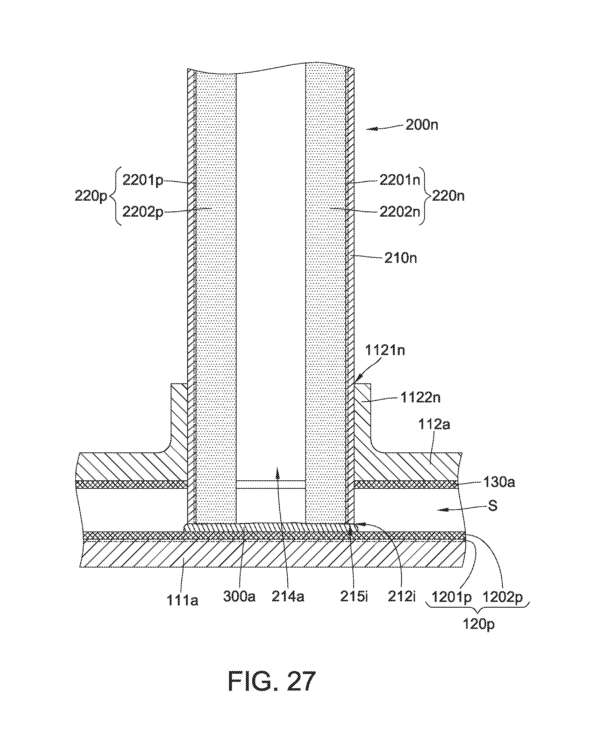
[0039] FIG. 27 is a cross-sectional view of the heat pipe coupled to a vapor chamber, according to example embodiments.
DETAILED DESCRIPTION
[0040] Detailed descriptions and technical contents of the present disclosure are illustrated below in conjunction with the accompany drawings. However, it is to be understood that the descriptions and the accompany drawings disclosed herein are merely illustrative and exemplary and not intended to limit the scope of the present disclosure.
[0041] The present disclosure provides a three-dimensional heat transfer device. FIGS. 1 to 4 show the first embodiment of the present disclosure, and FIGS. 5 to 7 show the second embodiment of the present disclosure.
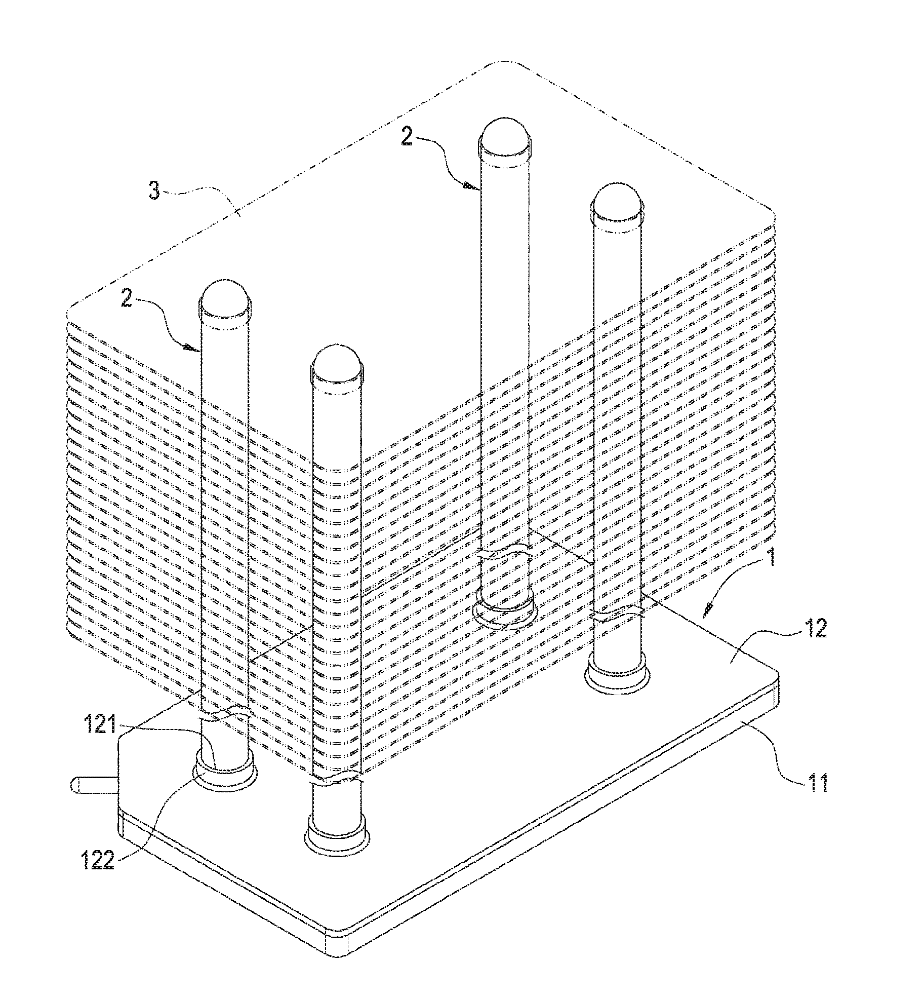
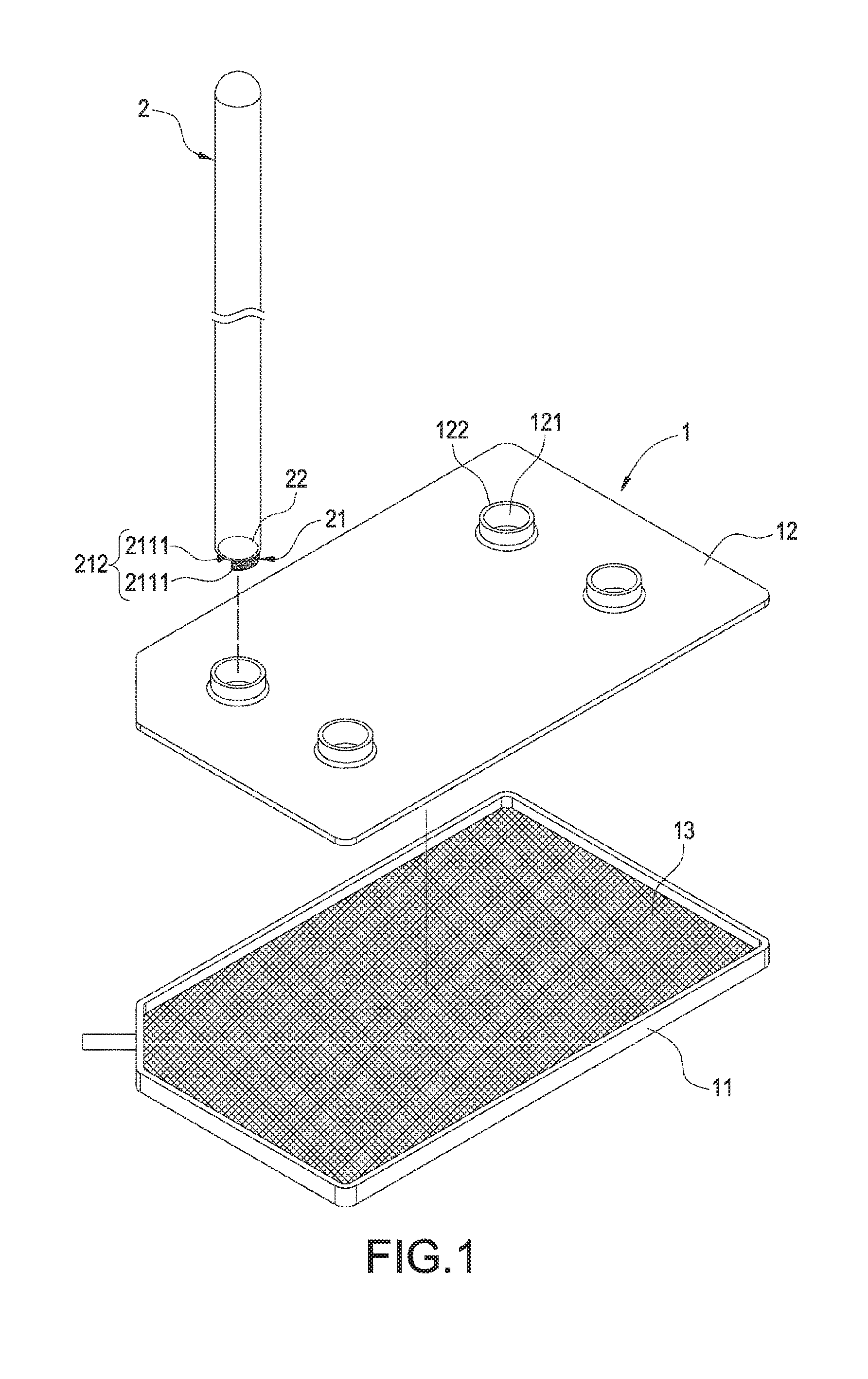
[0042] As shown in FIGS. 1 to 4, according to the first embodiment of the present disclosure, the three-dimensional heat transfer device includes a vapor chamber 1, at least one heat pipe 2 and a working fluid flowing inside the vapor chamber 1 and the heat pipe 2.
[0043] The vapor chamber 1 has a first plate 11 and a second plate 12 opposite to each other, and a cavity 10 is formed between the first plate 11 and the second plate 12. The vapor chamber 1 can be an integral structure and also can be a combined structure. In the present embodiment, the combined structure disclosed therein is merely representative for purposes of describing an example of the present disclosure. That is to say, the second plate 12 can be assembled to the first plate 11 to form the vapor chamber 1 having the cavity 10 inside.
[0044] A first capillary structure 13 is disposed on an inner surface of the first plate 11, a third capillary structure 14 (see FIG. 4) is disposed on an inner surface of the second plate 12, and the first and third capillary structures 13, 14 face each other. The first and third capillary structures 13, 14 can include sintered powder, sintered ceramic powder, metal web, or metal groove, and the present disclosure is not limited in this regard. However, in some embodiments, an inner surface of the second plate 12 is not disposed with the third capillary structure 14. In other words, only the inner surface of the first plate 11 is disposed with the capillary structure (i.e. the first capillary structure 13).
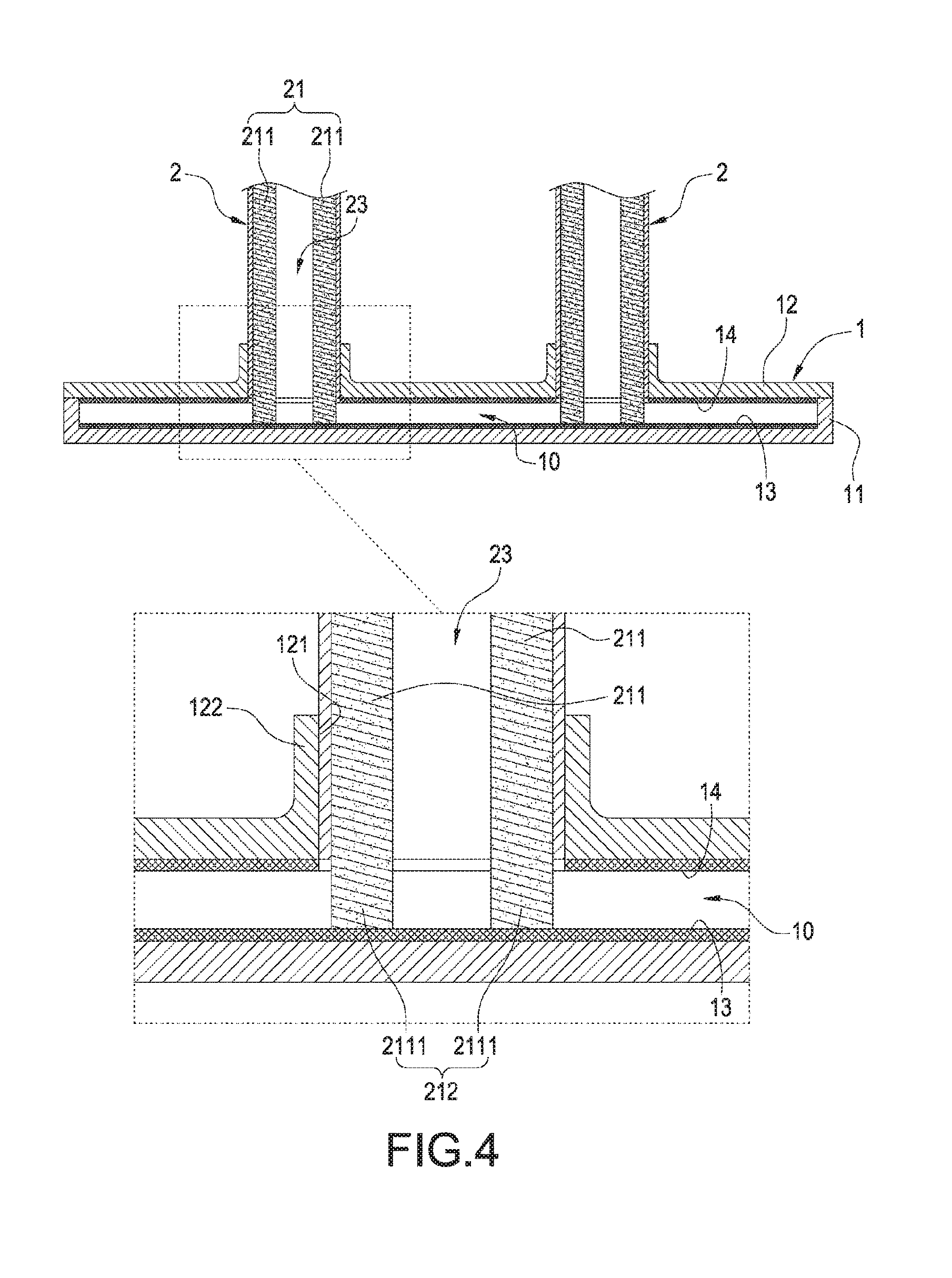
[0045] The second plate 12 forms at least one insertion hole 121. In the present embodiment, there are multiple insertion holes 121 for purposes of describing an example. Therefore, there are also multiple heat pipes 2 corresponding in number to the number of the insertion holes 121. Furthermore, a flange 122 in a circular form extends outwardly from a periphery of each insertion hole 121, thereby facilitating fixed connection with the heat pipe 2.
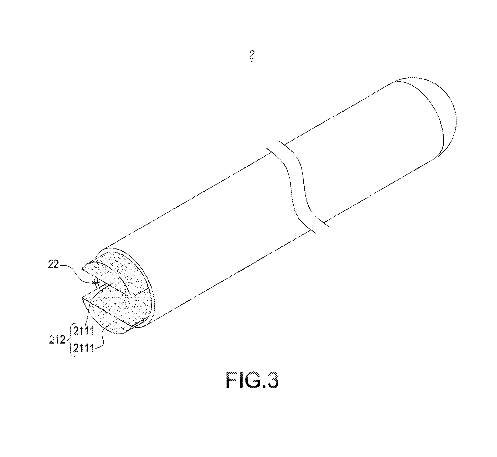
[0046] The heat pipe 2 is a hollow tube which has a second capillary structure 21 disposed inside, and the second capillary structure 21 has a contact portion 212 extending out of the heat pipe 2 to be exposed. In the present embodiment, one end (hereinafter referred to as the insertion end but not labelled) of the heat pipe 2 forms an opening 22 (see FIG. 3), the second capillary structure 21 includes two capillary elements 211 (see FIG. 4) arranged spaced apart and side by side so as to form a vapor passage 23 between the two capillary elements 211. Each of the two capillary elements 211 includes an exposed section 2111, the contact portion 212 consists of the exposed section 2111 of each of the two capillary elements 211, and thereby the vapor passage 23 of the heat pipe 2 communicates with the cavity 10 by means of the contact portion 212. The second capillary structure 21 can include sintered powder, ceramic powder, metal web or metal grooves, and the present disclosure is not limited in this regard. In the present embodiment, the second capillary structure 21 includes sintered powder for purposes of describing an example of the present disclosure.
[0047] Each heat pipe 2 is inserted through each insertion hole 121 correspondingly to be erected on the second plate 12, and the insertion end of the heat pipe 2 is utilized for insertion, so that the opening 22 is exposed within the cavity 10. The contact portion 212 of the second capillary structure 21 extends out from the opening 22 to be exposed, so the contact portion 212 extends into the cavity 10 to be connected to the first capillary structure 13, and thereby the first and second capillary structures 13, 21 communicate with each other.
[0048] In the present embodiment, for purposes of describing clear examples, the insertion end of the heat pipe 2 is inserted into the cavity 10 to contact a bottom thereof, so as to make the contact portion 212 in stable contact with the first capillary structure 13, and thereby the first and second capillary structures 13, 21 communicate with each other.
[0049] Each heat pipe 2 is inserted through the second plate 12 for fixed connection therewith by any suitable method such as making an outer wall surface of each heat pipe 2 in contact with the flange 122 and soldered thereto, thereby enhancing structural stability between the heat pipe 2 and the vapor chamber 1. Each heat pipe 2 is vertically inserted through the second plate 12, or the heat pipe 2 can form an included angle of 70 to 110 degrees with the second plate 12. The heat pipe 2 intersects the second plate 12, no matter whether the heat pipe 2 is vertically inserted or forms the included angle.
[0050] As shown in FIGS. 2 and 4, the heat pipe 2 inserted into the cavity of the vapor chamber 1 is in an erected condition, and the second capillary structure 21 inside the heat pipe 2 and the first capillary structure 13 inside the vapor chamber 1 contact and communicate with each other. As a result, an overall three-dimensional heat transfer effect can be achieved, thus desired ideal heat dissipation can be effected.
[0051] In addition, the two capillary elements 211 of the second capillary structure 21 and the two exposed sections 2111 thereof are spaced apart to form the vapor passage 23, so when the contact portion 212 of the heat pipe 2 is in contact with the first capillary structure 13, vapor can circulate via the vapor passage 23, and a hollow space inside the heat pipe 2 communicates with the cavity 10 of the vapor chamber 1, thereby enhancing heat dissipation. Certainly, after the contact portion 212 extending out of the heat pipe 2 and exposed therefrom is inserted into the cavity 10, a portion of the heat pipe 2, having the contact portion 212 extending out, also communicates with the cavity 10, thus having a function similar to the vapor passage 23.
[0052] In addition to contacting and communicating with the first capillary structure 13, the second capillary structure 21 of each heat pipe 2 can also connect and communicate with the third capillary structure 14. In fact, just by making the second capillary structure 21 contact and communicate with the first capillary structure 13, the second capillary structure 21 can dissipate heat properly.
[0053] Furthermore, as shown in FIG. 2, the three-dimensional heat transfer device can further include a fin set 3. The fin set 3 is assembled onto the heat pipe 2, so that the heat of the heat pipe 2 can be transferred to the fin set 3, thereby facilitating dissipating the heat of the fin set 3 by a fan not illustrated in the drawing.
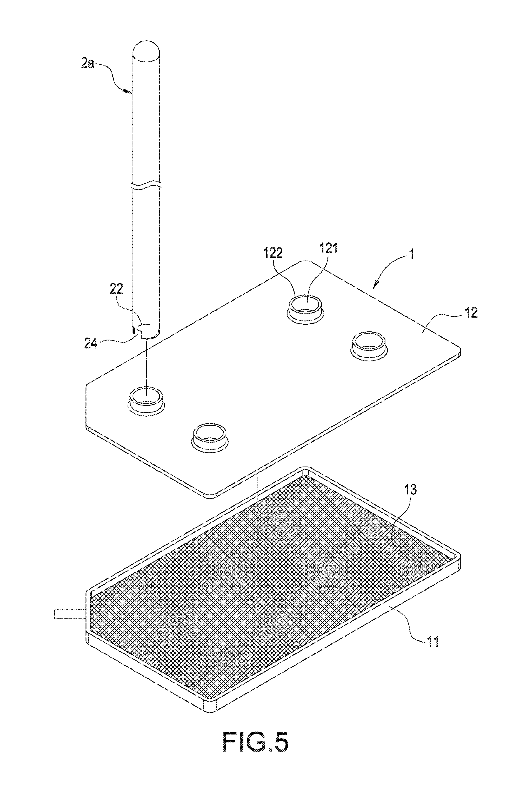
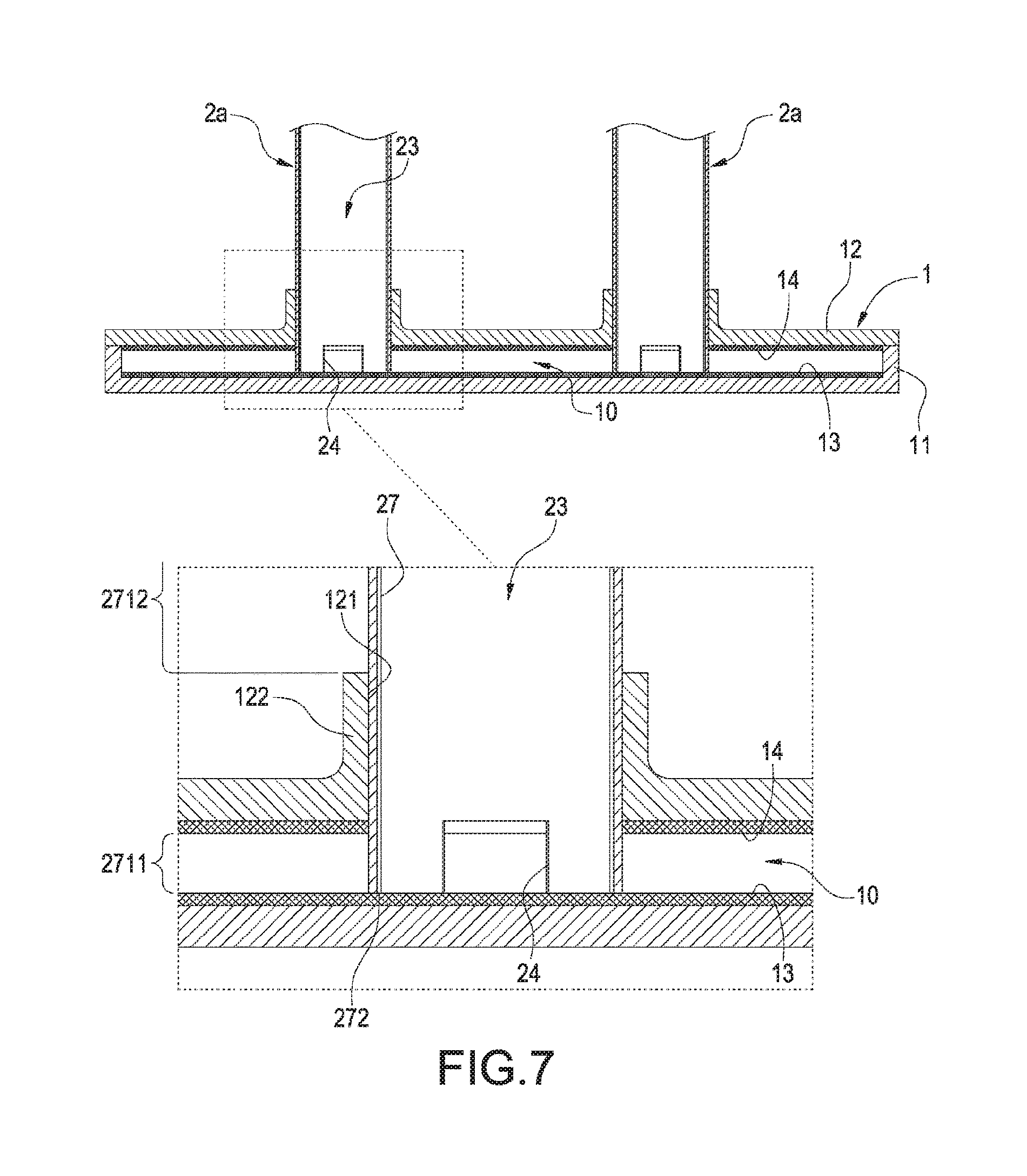
[0054] FIGS. 5 to 7 illustrate the three-dimensional heat transfer device according to the second embodiment of the present disclosure. The second embodiment is similar to the first embodiment with the difference that the heat pipe 2a in the second embodiment is different from the heat pipe 2 in the first embodiment, as more fully detailed below.
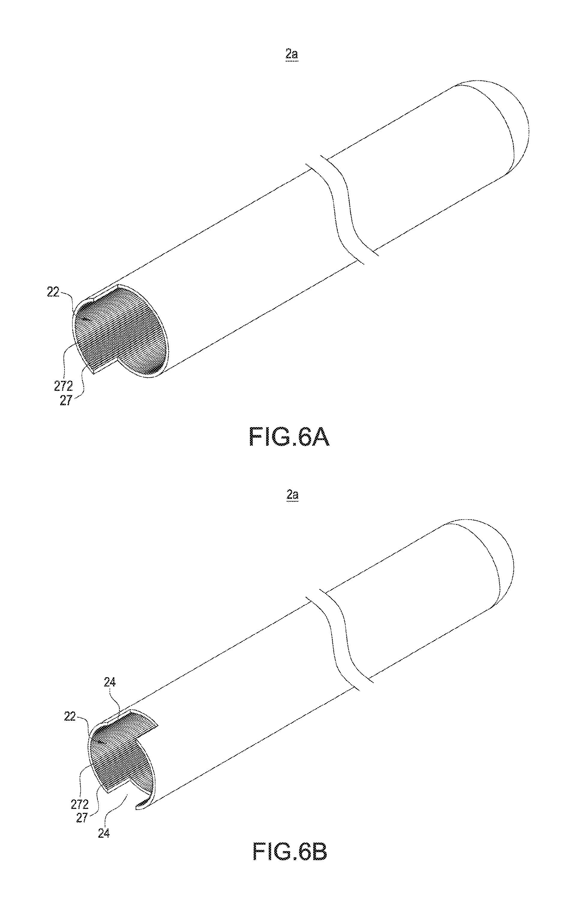
[0055] The heat pipe 2a (see FIG. 7) includes an inner section 2711 inside the cavity 10, an outer section 2712 outside the cavity 10, and an insertion section (not labelled) connected between the inner section 2711 and the outer section 2712 and fixed to the flange 122. A portion of the inner section 2711 forms an opening 22, and the opening 22 can be circular, rectangular or can be of a tear drop shape; the present disclosure is not limited in this regard. The opening 22 can be enlarged from a tube end (i.e. the insertion end) of the heat pipe 2a to a tube body to also permit circulation of the vapor (as shown in FIG. 6A). Alternatively, the opening 22 can be formed first, and then a plurality of gaps 24 (as shown in FIG. 5 or FIG. 6B) are formed directly on the tube body, so that the gaps 24 can serve as a vapor opening for the vapor to circulate therethrough. To be specific, the opening 22 is formed at a free end (i.e. the insertion end of the heat pipe 2a) of the inner section 2711, each gap 24 is formed at the inner section 2711 (which is also the tube body of the heat pipe 2a), and the gaps adjoin the opening 22 to communicate with each other, so the gaps 24 can serve as the vapor opening for the vapor to circulate therethrough.
[0056] The heat pipe in the second embodiment can be the heat pipe 2a of the first type in FIG. 6A and can also be the heat pipe 2a of the second type in FIG. 6B; the present disclosure is not limited in this regard, although for the purpose of describing the second embodiment, the heat pipe 2a of the second type shown in the FIG. 6B is taken as an example.
[0057] The second capillary structure 27 includes a contact portion 272 which is arranged in the opening 22 and exposed. In the present embodiment, the contact portion 272 is a rim of the second capillary structure 27, which is exposed corresponding to the opening 22. The contact portion 272 can be flush with or slightly shrink inwardly into the free end (or into the insertion end of the heat pipe 2a) of the inner section 2711.
[0058] The heat pipe 2a is vertically inserted through the second plate 12, and the inner section 2711 extends into the cavity 10, so that the contact portion 272 can be connected to the first capillary structure 13 via the opening 22 to make the first and second capillary structures 13, 27 communicate with each other. To be specific, the inner section 2711 contacts, by its free end, the first capillary structure 13, and therefore the contact portion 272 together with the inner section 2711 contacts the first capillary structure 13.
[0059] In summary, compared with conventional techniques, the present disclosure provides the following advantages. By making the second capillary structure 21, 27 of the heat pipe 2, 2a connected and communicating with the first capillary structure 13 of the vapor chamber 1, overall three-dimensional heat transfer is achieved, and a desired optimized heat dissipation effect can be obtained when the vapor chamber 1 collaborates with the heat pipe 2, 2a.
[0060] The present disclosure further has other advantages. By spacing the two capillary elements 211 to be apart from each other to form the vapor passage 23 or by forming the opening 22 of the heat pipe 2a, a hollow space inside the heat pipe 2, 2a is in communication with the cavity 10 of the vapor chamber 1, thereby promoting heat dissipation. Certainly, after the contact portion 212 extending out of the heat pipe 2 and exposed therefrom is inserted into the cavity 10, a portion of the heat pipe 2, having the contact portion 212 extending out, also communicates with the cavity 10, thus achieving an effect similar to the vapor passage 23.
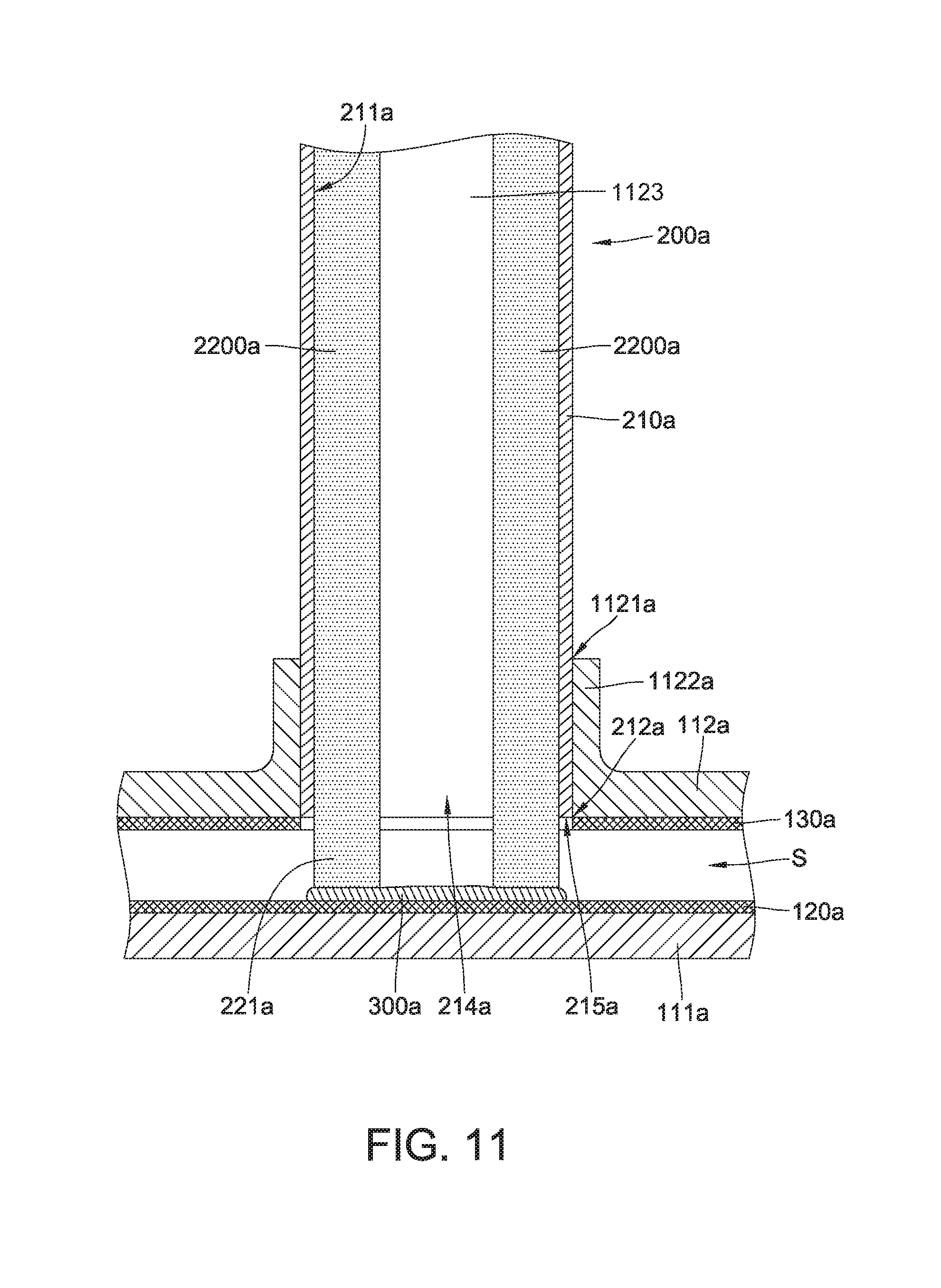
[0061] FIG. 8 is a perspective view of a heat transfer device 10a, according to the example embodiments. FIG. 9 is an exploded view of the heat transfer device 10a in FIG. 8 illustrating some of the components of the heat transfer device 10a. FIG. 10 is a cross-sectional view of the heat transfer device 10a in FIG. 8. FIG. 11 is an enlarged view of a portion of the heat transfer device 10a in FIG. 10. FIG. 12 is a perspective view of a heat pipe 200a in FIG. 9.
[0062] Referring to FIGS. 8-12, the three-dimensional (3D) heat transfer device 10a includes a vapor chamber 100a, multiple heat pipes 200a, and a fin assembly 400a including a plurality of fins. The vapor chamber 100a and the heat pipes 200a are configured to allow working fluid (e.g., vapor, in this case, but can be any liquid or gas) to flow in the vapor chamber 100a and the heat pipes 200a.
[0063] The vapor chamber 100a includes a chamber body 110a and a first capillary structure 120a. The chamber body 110a includes a first (or bottom) plate 111a and a second (or top) plate 112a. The first plate 111a includes a bottom part 115 and sidewalls 113 arranged along the periphery of the bottom part 115. The bottom part 115 and the sidewalls 113 thus define the general shape of the first plate 111a. The bottom part 115 is a generally planar structure and the sidewalls 113 are generally vertical structures arranged along the periphery of the bottom part 115. The second plate 112a is connected to the sidewalls 113 of the first plate 111a along the periphery thereof (e.g., along the edges of the second plate 112a), and the first plate 111a and the second plate 112a jointly define a cavity S. The cavity S is configured to accommodate the working fluid. In an example, and as illustrated, the first plate 111a and the second plate 112a are shown as separate components that are assembled together to form the chamber body 110a, but embodiments are not limited in this regard. In some other embodiments, the chamber body 110a is a unitary structure wherein the first plate 111a is integrally formed with the second plate 112a.
[0064] The first capillary structure 120a is disposed in the cavity S and on the bottom part 115 of the first plate 111a. In an embodiment, and as illustrated, the first capillary structure 120a is disposed on the entire bottom part 115; however, in other embodiments, the first capillary structure 120a may be disposed in a portion of the bottom part 115. The vapor chamber 100a further includes a third capillary structure 130a disposed in the cavity S and on a bottom surface 117 of the second plate 112a facing the first plate 111a. However, in other embodiments of the vapor chamber, the third capillary structure 130a is omitted, and the vapor chamber includes only the first capillary structure 120a. In an embodiment, the first capillary structure 120a and the third capillary structure 130a are selected from the group consisting of metal mesh, sintered metal powder, sintered ceramic, micro grooves, and combination thereof.
[0065] The second plate 112a includes multiple through holes 1121a, each including a flange 1122a along the edges of the through holes 1121a and that projects vertically upward from a top surface 119 of the second plate 112a opposite the bottom surface 117. The through holes 1121a are arranged in a pattern on the second plate 112a; however, the arrangement of the through holes 1121a is not limited in this regard. The number of the through holes 1121a is equal to the number of the heat pipes 200a. For example, when the 3D heat transfer device 10a includes single heat pipe 200a, the second plate 112a includes a single through hole 1121a. Each flange 1122a is connected to the edge of the corresponding through hole 1121a and is shaped and sized, or otherwise configured, for receiving a heat pipe 200a therewithin.
[0066] Referring to FIGS. 10-12, each of the heat pipes 200a includes a pipe body 210a and a second capillary structure 220a disposed along the inner circumferential surface 211a of the pipe body 210a. In an embodiment, and as illustrated, the pipe body 210a is a generally cylindrical hollow tube. Each pipe body 210a includes an open end 212a and a closed end 213a opposite the open end 212a. The open end 212a of the pipe body 210a includes an opening 214a (FIGS. 11 and 12) of the pipe body 210a and an edge 215a of the pipe body 210a that defines the opening 214a. The second capillary structure 220a includes two capillary elements 2200a disposed on and lining the inner circumferential surface 211a. The two capillary elements 2200a are arranged circumferentially and radially spaced apart (e.g., non-contacting) from each other to define a vapor passage 1123. Each capillary element 2200a includes a curved or arched surface that contacts the inner circumferential surface 211a and a planar surface that faces the interior of the pipe body 210a and defines the vapor passage 1123. An axial end 2207 of each capillary element 2200a contacts the interior of the pipe body 210a at the closed end 213a, and the opposite axial end 2209 of each capillary element 2200a includes a contact portion 221a extending axially out of the pipe body 210a a certain distance from the edge 215a of the pipe body 210a. The contact portion 221a thus forms an exposed portion of the capillary element 2200a. In an embodiment, the second capillary structure 220a is a sintered solid part including metal powder, but embodiments are not limited in this regard. In some other embodiments, the second capillary structure is selected from the group consisting of metal mesh, sintered metal powder, sintered ceramic, micro grooves, and combination thereof.
[0067] Each heat pipe 200a is inserted in the through hole 1121a, and each capillary element 2200a of the second capillary structure 220a is connected to the first capillary structure 120a by metallic bonding. Referring to FIGS. 10 and 11, the 3D heat transfer device 10a further includes a bonding layer 300a including gold powder, silver powder, copper powder, iron powder, a combination thereof, and the like. The powder(s) is/are sintered to form the bonding layer 300a including a porous structure. One surface of the bonding layer 300a is connected to the first capillary structure 120a by metallic bonding, and the other opposite surface of the bonding layer 300a is connected to the second capillary structure 220a by metallic bonding.
[0068] In conventional heat transfer devices, metal bonding layer is not included between capillary structures, and the capillary structures directly contact each other. The bonding layer 300a, according to example embodiments, provides a metallic bonding between the first capillary structure 120a and the second capillary structure 220a and improves the flow rate of the working fluid between the second capillary structure 220a and the first capillary structure 120a, thereby increasing a heat dissipation efficiency of the 3D heat transfer device 10a.
[0069] A method of manufacturing the 3D heat transfer device 10a includes providing a vapor chamber 100a including a first capillary structure 120a. At least part of the first capillary structure 120a includes a metal powder. The method then includes contacting a second capillary structure 220a of a heat pipe 200a with the first capillary structure 120a. A sintering process is then performed to sinter the metal powder to form the bonding layer 300a. The bonding layer 300a is connected to the first capillary structure 120a and the second capillary structure 220a by metallic bonding.
[0070] According to example embodiments, the 3D heat transfer device 10a includes multiple (four, in this case) heat pipes 200a, but embodiments are not limited thereto. In some other embodiments, the 3D heat transfer device 10a includes a single heat pipe 200a or more than four heat pipes 200a. The multiple heat pipes 200a, and the corresponding through holes 1121a, can be arranged in any desired manner on the vapor chamber 100a.
[0071] According to example embodiments, the second capillary structure 220a of the heat pipe 200a is connected to the first capillary structure 120a by metallic bonding, while metallic bonding is absent between the first capillary structure 120a and the third capillary structure 130a. However, embodiments are not limited in this regard. In other embodiments, the second capillary structure 220a is connected to both the first capillary structure 120a and the third capillary structure 130a by metallic bonding.
[0072] Referring to FIG. 8, the fin assembly 400a including a plurality of fins disposed on the heat pipes 200a improves the heat dissipation efficiency of the 3D heat transfer device 10a. Herein, the heat generated by a heat source is transferred through the heat pipes 200a to the fin assembly 400a, thereby increasing the surface area for heat dissipation and providing increased heat dissipation in a relatively smaller area.
[0073] FIGS. 13-19 illustrate different embodiments of heat pipes 200b-200h, each of which may be used in place of the heat pipe 200a.
[0074] FIG. 13 is a perspective view of a heat pipe 200b according to example embodiments. The heat pipe 200b may be similar in some respects to the heat pipe 200a in FIG. 12, and therefore may be best understood with reference thereto where like numerals designate like components not described again in detail. As illustrated, the heat pipe 200b includes a second capillary structure 220b disposed on and lining the inner circumferential surface 211a of the pipe body 210a. The second capillary structure 220b includes two capillary elements 2200b similar to the capillary elements 2200a. Each capillary element 2200b is disposed on and lines (contacts) the inner circumferential surface 211a, and is circumferentially spaced apart from the other capillary element 2200b. An axial end 2207 of each capillary element 2200b inside the pipe body 210a is axially spaced from the closed end 213b, and the other opposite axial end 2209 of each capillary element 2200b includes a contact portion 221a extending axially out of the pipe body 210a a certain distance from the edge 215a of the pipe body 210a and thereby exposed. In an embodiment, the length (e.g., axial extent) of each capillary element 2200b is about half of the length (e.g., axial extent) of the pipe body 210a, and the axial end 2207 is located below the mid-point of the heat pipe 200b. However, embodiments are not limited in this regard. In an embodiment, the length of each capillary element 2200b is greater than half the length of the pipe body 210a, but the capillary element 2200b does not contact the closed end 213a. In another embodiment, the length of each capillary element 2200b is less than half the length of the pipe body 210a. In yet another embodiment, the two capillary elements 2200b may have different lengths.
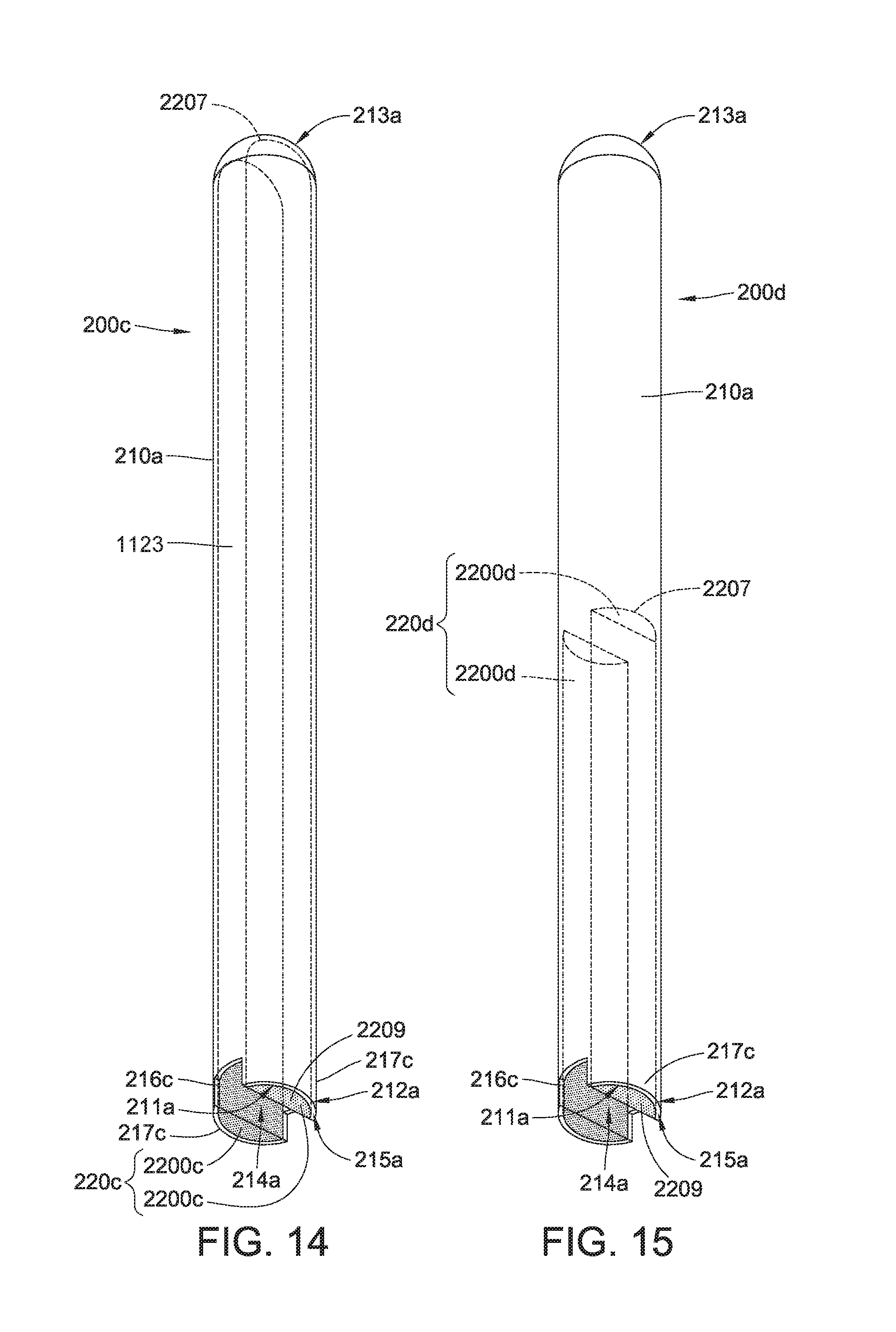
[0075] FIG. 14 is a perspective view of a heat pipe 200c according to example embodiments. The heat pipe 200c may be similar in some respects to the heat pipe 200a in FIG. 12, and therefore may be best understood with reference thereto where like numerals designate like components not described again in detail. As shown in FIG. 14, the heat pipe 200c includes a second capillary structure 220c disposed on and lining the inner circumferential surface 211a of the pipe body 210a. The second capillary structure 220c includes two capillary elements 2200c similar to the capillary elements 2200a. Each capillary element 2200c is disposed on and lines the inner circumferential surface 211a, and is circumferentially and radially spaced apart from the other capillary element 2200c. The axial end 2207 of each capillary element 2200c inside the pipe body 210a contacts the interior of the pipe body 210a at the closed end 213a, and the other opposite end 2209 of each capillary element 2200c is flush with the edge 215a. In an embodiment, the length (e.g., axial extent) of the capillary element 2200c is substantially equal to the length (e.g., axial extent) of the pipe body 210a including projections 217c (see below). However, in other embodiments, the capillary elements 2200c may have different lengths, wherein the end 2207 of a capillary element 2200c is axially spaced from the pipe body 210a at the closed end 213a.
[0076] At the open end 212a, the pipe body 210a includes recesses 216c (two shown) extending axially from the edge 215a, and projections 217c (two shown) formed by the recesses 216c at the open end 212a. As illustrated, each capillary element 2200c extends from the closed end 213a to the edge 215a included in a projection 217c and flush with the edge 215a. In an embodiment, and as illustrated, the capillary elements 2200c do not extend into the recesses 216c. The recesses 216c are in fluid communication with the opening 214a and thereby with the vapor passage 1123. Each recess 216c is shaped and sized, or otherwise configured, to provide a fluid path through which working fluid, such as vapor, flows.
[0077] FIG. 15 is a perspective view of a heat pipe 200d according to example embodiments. The heat pipe 200d may be similar in some respects to the heat pipe 200c in FIG. 14, and therefore may be best understood with reference thereto where like numerals designate like components not described again in detail. As illustrated in FIG. 15, the heat pipe 200d includes a second capillary structure 220d disposed on and lining the inner circumferential surface 211a. The second capillary structure 220d includes two capillary elements 2200d disposed on and lining the inner circumferential surface 211a, and spaced apart from each other. The end 2207 of each capillary element 2200d inside the pipe body 210a is axially spaced from the closed end 213d, and the opposite axial end 2209 of the capillary element 2200d is flush with the edge 215a. In an embodiment, the length (e.g., axial extent) of each capillary element 2200d is about half of the length (e.g., axial extent) of the pipe body 210a. However, embodiments are not limited in this regard. In an embodiment, the length of each capillary element 2200d is greater than half the length of the pipe body 210a, but the capillary element 2200d does not contact the closed end 213a. In another embodiment, the length of each capillary element 2200d is less than half the length of the pipe body 210a. In yet another embodiment, the capillary elements 2200d may have different lengths.
[0078] FIG. 16 is a perspective view of a heat pipe 200e according to example embodiments. The heat pipe 200e may be similar in some respects to the heat pipe 200a in FIG. 12, and therefore may be best understood with reference thereto where like numerals designate like components not described again in detail. As illustrated in FIG. 16, the heat pipe 200e includes a second capillary structure 220e disposed on and lining the inner circumferential surface 211a.
[0079] As illustrated, the second capillary structure 220e lines the entire inner circumferential surface 211a. The second capillary structure 220e is a generally tubular structure having an outer circumferential surface contacting the inner circumferential surface 211a and an inner circumferential surface that defines the vapor passage 1123 that extends the axial length of the second capillary structure 220e. One end of the second capillary structure 220e contacts the interior surface of the pipe body 210a at the closed end 213e, and the other opposite end of the second capillary structure 220e includes contact portion 221a extending axially out of the pipe body 210a a certain distance from the edge 215a of the pipe body 210a, and is thereby exposed. Specifically, the length of the second capillary structure 220e is substantially equal to the length of the pipe body 210e. In an embodiment, the contact portion 221a includes two (or more) projections 223 circumferentially separated from each other by recesses 225 (two shown) defined in the second capillary structure 220e. Each recess 225 may extend axially from an axial end of the second capillary structure 220e in the contact portion 221a, and a bottom of each recess 225 is flush with the edge 215a of the pipe body 210a.
[0080] FIG. 17 is a perspective view of a heat pipe 200f according to example embodiments. The heat pipe 200f may be similar in some respects to the heat pipe 200e in FIG. 16, and therefore may be best understood with reference thereto where like numerals designate like components not described again in detail. As illustrated in FIG. 17, the heat pipe 200f includes a second capillary structure 220f disposed on and lining an inner circumferential surface 211a. The second capillary structure 220f is similar to the second capillary structure 220e in FIG. 16, except that the axial end 2207 of the second capillary structure 220f inside the pipe body 210a is axially spaced from the closed end 213a. In an embodiment, the length (e.g., axial extent) of the second capillary structure 220f is about half of the length of the pipe body 210a. However, embodiments are not limited in this regard. In an embodiment, the length of the second capillary structure 220f is greater than half the length of the pipe body 210a, but the second capillary structure 220f does not contact the closed end 213a. In another embodiment, the length of the second capillary structure 220f is less than half the length of the pipe body 210a.
[0081] FIG. 18 is a perspective view of a heat pipe 200g according to example embodiments. The heat pipe 200g may be similar in some respects to the heat pipes 200c and 200e in FIGS. 14 and 16, respectively, and therefore may be best understood with reference thereto where like numerals designate like components not described again in detail. As illustrated in FIG. 18, the heat pipe 200g includes a second capillary structure 220g disposed on and lining the entire inner circumferential surface 211a of the pipe body 210a. The open end 212a of the pipe body 210a includes recesses 216c and two projections 217c similar to the heat pipe 200c in FIG. 14 The second capillary structure 220g includes two projections 223 circumferentially separated from each other by recesses 225 defined in the second capillary structure 220g at the open end 212a The second capillary structure 220g is flush with the pipe body 210a in the recesses 216c. The projections 223 of the second capillary structure 220g also line the inner circumferential surface 211a of the pipe body 210a in the projections 217c. The number of projections 223 correspond to the number of projections 217c. The projections 223 of the second capillary structure 220g are flush with the projections 217c of the pipe body 210a.
[0082] FIG. 19 is a perspective view of a heat pipe 200h according to example embodiments. The heat pipe 200h may be similar in some respects to the heat pipe 200g in FIG. 18, and therefore may be best understood with reference thereto where like numerals designate like components not described again in detail. As illustrated in FIG. 19, the heat pipe 200h includes a second capillary structure 220h disposed on and lining an inner circumferential surface 211a. The second capillary structure 220h is similar to the second capillary structure 220g in FIG. 18, except that the axial end 2207 of the second capillary structure 220h inside the pipe body 210a is axially spaced from the closed end 213a. In an embodiment, the length (e.g., axial extent) of the second capillary structure 220h is about half of the length of the pipe body 210a. However, embodiments are not limited in this regard. In an embodiment, the length of the second capillary structure 220h is greater than half the length of the pipe body 210a, but the second capillary structure 220h does not contact the closed end 213a. In another embodiment, the length of the second capillary structure 220h is less than half the length of the pipe body 210a.
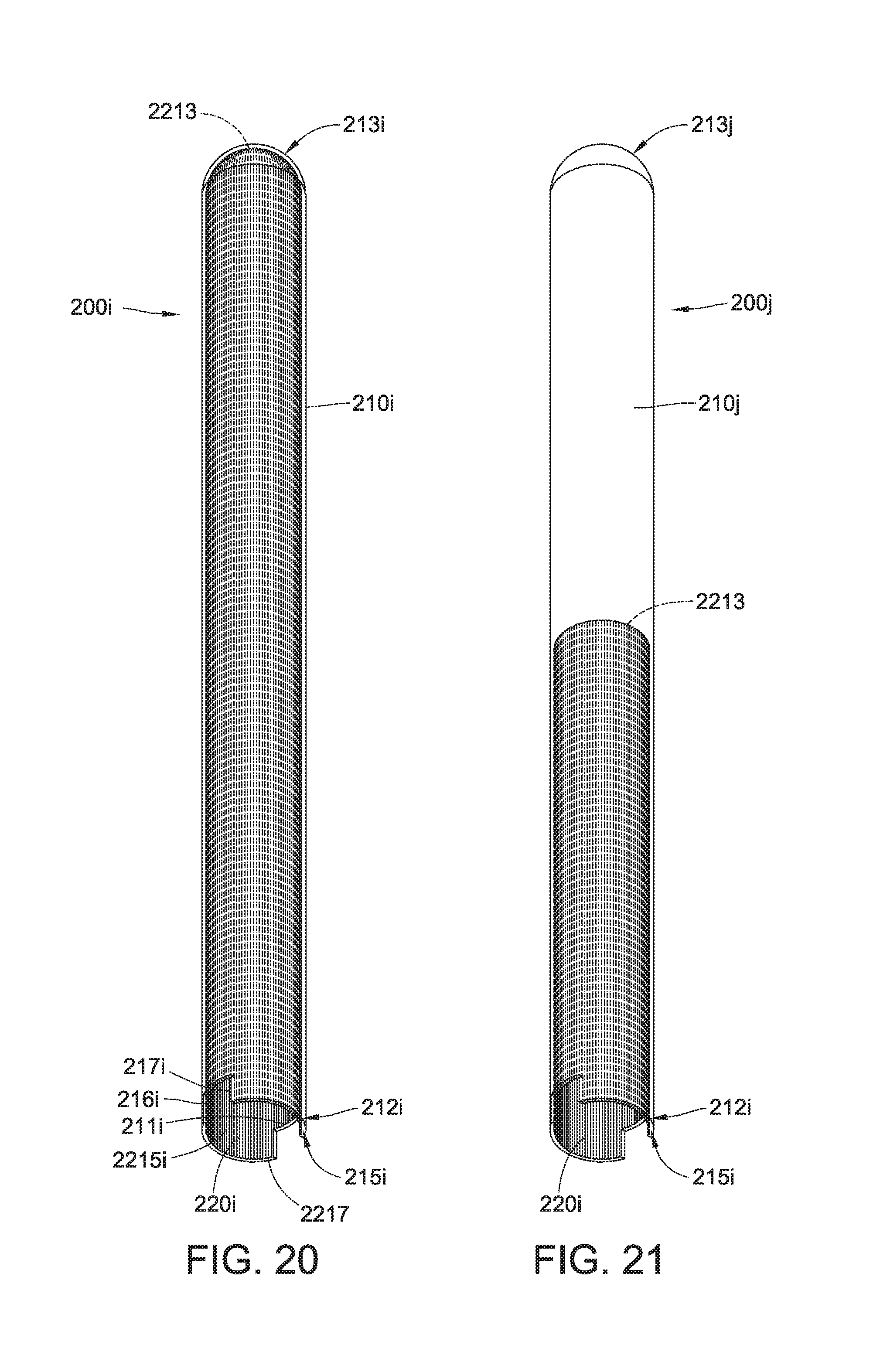
[0083] FIG. 20 is a perspective view of a heat pipe 200i according to the example embodiments. As illustrated in FIG. 20, the heat pipe 200i includes a pipe body 210i and a second capillary structure 220i. The pipe body 210i is a generally cylindrical hollow tube that includes an open end 212i and an axially opposite closed end 213i. The open end 212i of the pipe body 210i includes an edge 215i. The second capillary structure 220i is disposed on and lines an entire inner circumferential surface 211i of the pipe body 210i and defines the vapor passage 1123. In an embodiment, the second capillary structure 220i includes multiple micro grooves 2215i. The micro grooves 2215i extend axially along the inner circumferential surface 211i between the closed end 213i and open end 212i. An axial end 2213 of each micro groove 2215i contacts the interior surface of the pipe body 210i at the closed end 213i, and the other axially opposite end 2217 of each micro groove 2215i is flush with the edge 215i. In an embodiment, the micro grooves 2215i extend an entire axial length of the pipe body 210i. The pipe body 210i includes multiple (two shown) recesses 216i extending axially from the edge 215i. The recesses 216i define projections 217i at the open end 212i. It will thus be understood that, the micro grooves 2215i that end in the recesses 216i have a smaller length that the micro grooves 2215i that end at the edges 215i.
[0084] FIG. 21 is a perspective view of a heat pipe 200j according to example embodiments. The heat pipe 200j may be similar in some respects to the heat pipe 200i in FIG. 20, and therefore may be best understood with reference thereto where like numerals designate like components not described again in detail. As illustrated, the end 2213 of each micro groove 2215i is axially spaced from the closed end 213j, and the axially opposite end 2217 of the micro grooves 2215i is flush with the edge 215j or with the recess 216i. In an embodiment, the length of the micro groove 2215i extending along the inner circumferential surface 211i and along the projections 217i is about half of the length of the pipe body 210j.
[0085] FIG. 22 is a perspective view of a heat pipe 200k according to example embodiments. The heat pipe 200k may be similar in some respects to the heat pipe 200i in FIG. 20, and therefore may be best understood with reference thereto where like numerals designate like components not described again in detail. As illustrated in FIG. 22, the heat pipe 200k includes a second capillary structure 220k similar to the second capillary structure 220i, except that the second capillary structure 220k includes two capillary elements 2200k disposed on and lining the inner circumferential surface 211i of the pipe body 210k. The two capillary elements 2200k are circumferentially and radially spaced apart from each other, and define vapor passage 1123 therebetween. Each capillary element 2200k includes a plurality of micro grooves 2215i. An end 2213 of the micro grooves 2215i contacts the interior surface of the heat pipe 200k at the closed end 213k, and the micro grooves 2215i extend on the projections 217i and the axially opposite end of the micro grooves 2215i is flush with the edge 215i of the pipe body 210i in the projections 217i. In an embodiment, the length of each micro groove 2215i is substantially equal to the length of the pipe body 210i including the projections 217i. As illustrated, the micro grooves 2215i are absent in the axial portion of the pipe body 210i between the recess 216i and the closed end 213i.
[0086] FIG. 23 is a perspective view of a heat pipe 200m according to example embodiments. The heat pipe 200m may be similar in some respects to the heat pipe 200j in FIG. 21, and therefore may be best understood with reference thereto where like numerals designate like components not described again in detail. As illustrated, the heat pipe 200m includes a second capillary structure 220m similar to the second capillary structure 220i in FIG. 21, except that the second capillary structure 220m includes two capillary elements 2200m disposed on and lining the inner circumferential surface 211i of the pipe body 210m. The two capillary elements 2200m are circumferentially and radially spaced apart from each other. Each capillary element 2200m includes multiple micro grooves 2215i. An end 2213 of each micro groove 2215i is axially spaced from the closed end 213i, and the other axially opposite end 2217 of each micro groove 2215i is flush with the edge 215i of the pipe body 210i in the projections 217i. In an embodiment, the length of the micro grooves 2215i is about half of the length of the pipe body 210i including the projections 217i. However, embodiments are not limited in this regard. In an embodiment, the length of micro grooves 2215i is greater than half the length of the pipe body 210a, but the micro grooves 2215i do not contact the closed end 213i. In another embodiment, the length of the micro grooves 2215i is less than half the length of the pipe body 210a. In yet another embodiment, the micro grooves 2215i in one capillary element 2200m and the micro grooves 2215i in the other capillary element 2200m may have different lengths.
[0087] In the aforementioned embodiments of the heat pipes in FIGS. 13-23, the second capillary structures may include either a metal mesh, a sintered solid part made of metal powder, a sintered ceramic, multiple micro grooves, a combination thereof, and the like.
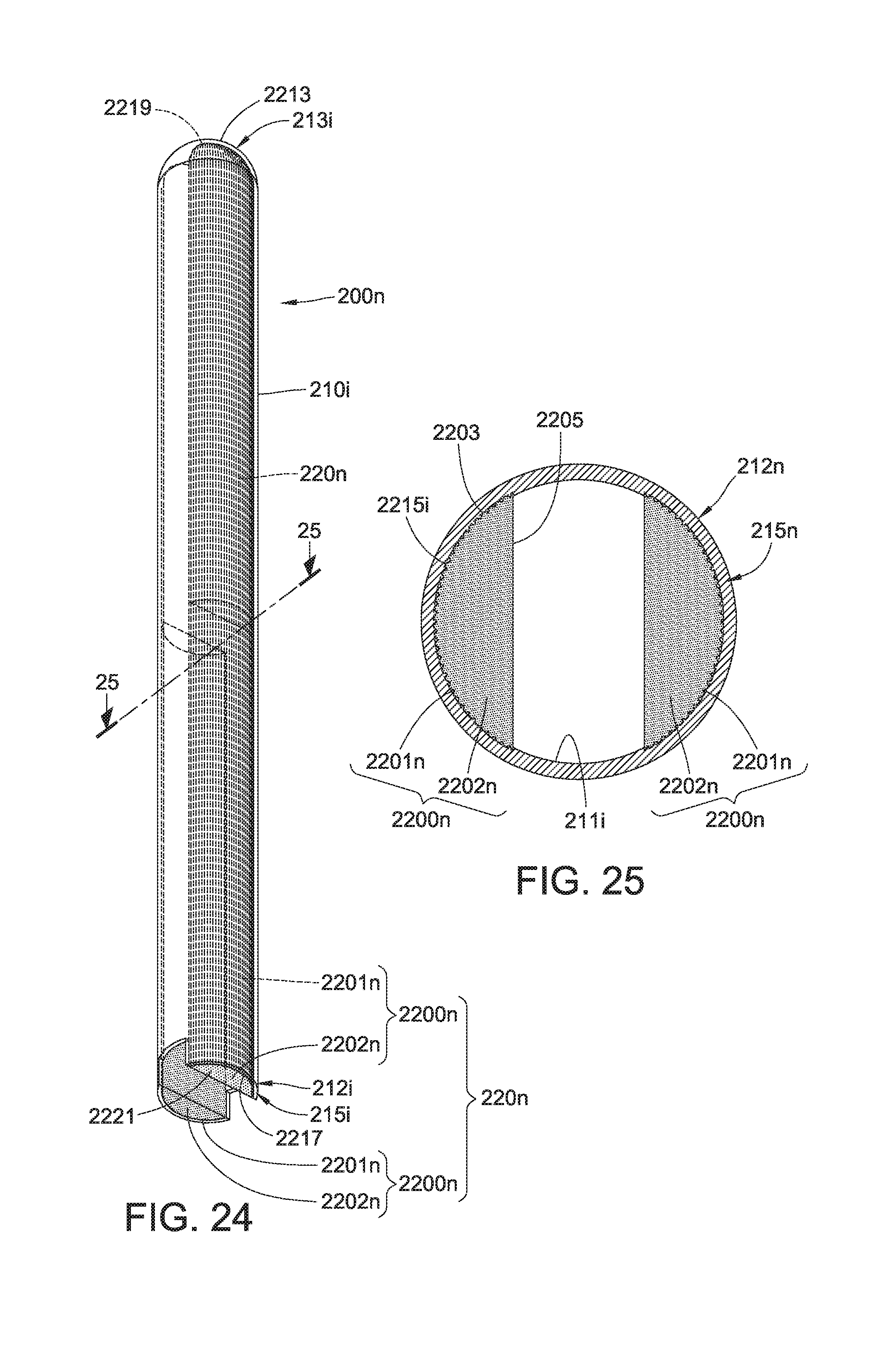
[0088] FIG. 24 is a perspective view of a heat pipe 200n according to example embodiments. FIG. 25 is a cross-sectional view of the heat pipe 200n in FIG. 24. The heat pipe 200n may be similar in some respects to the heat pipe 200k in FIG. 22, and therefore may be best understood with reference thereto where like numerals designate like components not described again in detail.
[0089] Referring to FIGS. 24 and 25, the heat pipe 200n includes a second capillary structure 220n that includes two capillary elements 2200n disposed on and contacting the inner circumferential surface 211i of the pipe body 210i.
[0090] The second capillary structure 220n is a composite capillary structure. Each capillary element 2200n includes a curved or arched surface 2203 contacting the inner circumferential surface 211i and a generally planar surface 2205 extending between ends of the curved surface 2203. The capillary element 2200n includes a first layer 2201n disposed on the curved surface 2203 and a second layer 2202n disposed on the first layer 2201n and including the planar surface 2205. The first layer 2201n includes multiple micro grooves 2215i. An axial end 2213 of the first layer 2201n contacts the interior surface of the heat pipe 200n at the close end 213n, and the other axially opposite end 2217 of the first layer 2201n is flush with the edge 215n of the pipe body 210n. The second layer 2202n includes a metal mesh, a sintered solid part made of metal powder or a sintered ceramic. An axial end 2219 of the second layer 2202n contacts the interior surface of the heat pipe 200n at the close end 213n, and the other axially opposite end 2221 of the second layer 2202n is flush with the edge 215n of the pipe body 210n.
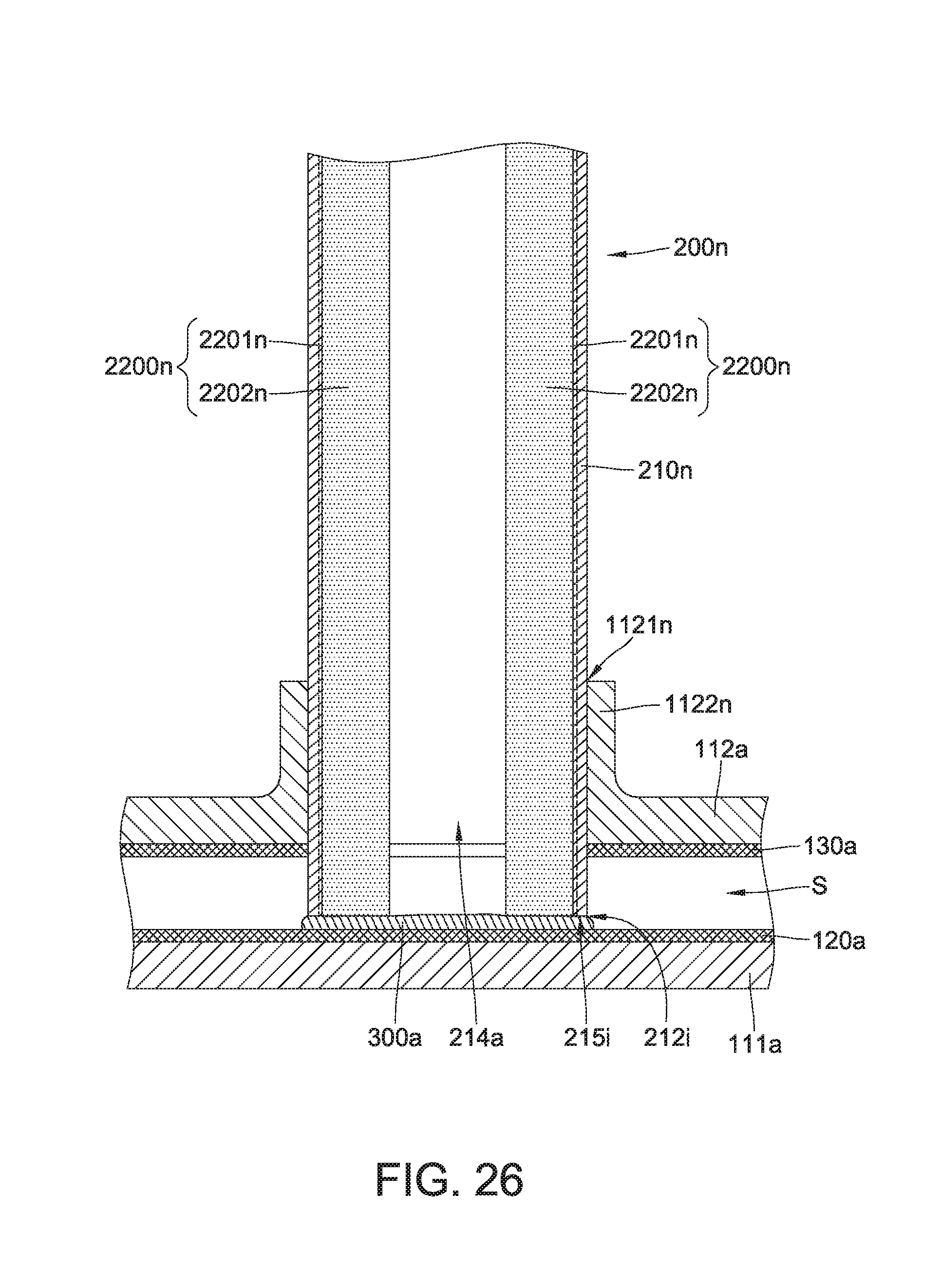
[0091] FIG. 26 is a cross-sectional view of the heat pipe 200n in FIG. 24 connected to a vapor chamber, according to example embodiments. In an embodiment, the vapor chamber may be similar in some respects to the vapor chamber 100a in FIGS. 8-11. In an embodiment, the heat pipe 200n is inserted through a through hole 1121n of second plate 112a. Both the first layer 2201n and the second layer 2202n of the second capillary structure 220n are connected to the first capillary structure 120a (FIG. 8) via bonding layer 300a. More specifically, the bonding layer 300a is connected to the first capillary structure 120a and the second capillary structure 220n by metallic bonding.
[0092] FIG. 27 is a cross-sectional view of the heat pipe 200n coupled to a vapor chamber 100p, according to example embodiments. The vapor chamber 100p may be similar in some respects to the vapor chamber 100a in FIGS. 8-11, and therefore may be best understood with reference thereto where like numerals designate like components not described again in detail. The vapor chamber includes a first capillary structure 120p in the first plate 111a. The first capillary structure 120p is a composite capillary structure including a first layer 1201p and a second layer 1202p. The first layer 1201p contact the bottom part 115 of the first plate 111a, and the second layer 1202p is disposed on the first layer 1201p. The first layer 1201p includes multiple micro grooves, and the second layer 1202p of the first capillary structure 120p includes a metal mesh, a sintered solid part made of metal powder or a sintered ceramic. Both a first layer 2201n and a second layer 2202n of a second capillary structure 220n are connected to the second layer 1202p of the first capillary structure 120p via a bonding layer 300a. More specifically, the bonding layer 300p is connected to the first layer 2201n, the second layer 2202n, and the second layer 1202p by metallic bonding.
[0093] In a conventional heat dissipation devices, the first capillary structure merely contacts the second capillary structure without metal bonding, and the working fluid is retained in the second capillary structure due to an adhesive force between the working fluid and the second capillary structure. According to example embodiments, the first capillary structure is coupled to the second capillary structure by metallic bonding. The metallic bonding encourages flow of the working fluid from the second capillary structure into the first capillary structure. Therefore, a flow rate of the working fluid is increased and the heat dissipation efficiency of the 3D heat transfer device is improved.
[0094] It is to be understood that the above descriptions are merely the preferable embodiment of the present disclosure and are not intended to limit the scope of the present disclosure. Equivalent changes and modifications made in the spirit of the present disclosure are regarded as falling within the scope of the present disclosure.
* * * * *
D00000
D00001
D00002
D00003
D00004
D00005
D00006
D00007
D00008
D00009
D00010
D00011
D00012

D00013
D00014

D00015

D00016
D00017

D00018
D00019
D00020
XML
uspto.report is an independent third-party trademark research tool that is not affiliated, endorsed, or sponsored by the United States Patent and Trademark Office (USPTO) or any other governmental organization. The information provided by uspto.report is based on publicly available data at the time of writing and is intended for informational purposes only.
While we strive to provide accurate and up-to-date information, we do not guarantee the accuracy, completeness, reliability, or suitability of the information displayed on this site. The use of this site is at your own risk. Any reliance you place on such information is therefore strictly at your own risk.
All official trademark data, including owner information, should be verified by visiting the official USPTO website at www.uspto.gov. This site is not intended to replace professional legal advice and should not be used as a substitute for consulting with a legal professional who is knowledgeable about trademark law.