Home Appliance Device
CIYANOGLU; MEHMET ; et al.
U.S. patent application number 15/570457 was filed with the patent office on 2019-02-14 for home appliance device. The applicant listed for this patent is BSH HAUSGERAETE GMBH. Invention is credited to MEHMET CIYANOGLU, MUSTAFA ERTIK, NECATI BORA GUEREL, STEPHAN KEMPFLE, AYDIN SAHIN, AHMET SAYGI, MURAT SOEGUET, ERDEM SUEMER, TANZER YILDIZGOECER.
| Application Number | 20190049169 15/570457 |
| Document ID | / |
| Family ID | 55858766 |
| Filed Date | 2019-02-14 |


| United States Patent Application | 20190049169 |
| Kind Code | A1 |
| CIYANOGLU; MEHMET ; et al. | February 14, 2019 |
HOME APPLIANCE DEVICE
Abstract
A home appliance device, in particular a home appliance chiller device, with improved efficiency, includes a refrigerant cycle having a heat generating unit, a machine compartment having a first sub-compartment and a second sub-compartment separated from the first sub-compartment. The second sub-compartment is configured for at least partly receiving the heat generating unit. An airflow unit is configured for conveying air from the first sub-compartment to the second sub-compartment in such a way that, in operation, the second sub-compartment is kept at least substantially warmer than the first sub-compartment. A home appliance including the home appliance device is also provided.
| Inventors: | CIYANOGLU; MEHMET; (ISTANBUL, TR) ; ERTIK; MUSTAFA; (TEKIRDAG, TR) ; GUEREL; NECATI BORA; (TEKIRDAG, TR) ; KEMPFLE; STEPHAN; (ELLZEE, DE) ; SAHIN; AYDIN; (ISTANBUL, TR) ; SAYGI; AHMET; (TEKIRDAG, TR) ; SOEGUET; MURAT; (TEKIRDAG, TR) ; SUEMER; ERDEM; (TEKIRDAG, TR) ; YILDIZGOECER; TANZER; (TEKIRDAG, TR) | ||||||||||
| Applicant: |
|
||||||||||
|---|---|---|---|---|---|---|---|---|---|---|---|
| Family ID: | 55858766 | ||||||||||
| Appl. No.: | 15/570457 | ||||||||||
| Filed: | April 28, 2016 | ||||||||||
| PCT Filed: | April 28, 2016 | ||||||||||
| PCT NO: | PCT/EP2016/059513 | ||||||||||
| 371 Date: | October 30, 2017 |
| Current U.S. Class: | 1/1 |
| Current CPC Class: | F25D 23/028 20130101; F25D 2323/0026 20130101; F25D 23/003 20130101; F25D 25/021 20130101; F25D 2323/02 20130101; F25D 29/005 20130101; F25D 2323/00266 20130101; F25D 2323/002 20130101; F25D 11/02 20130101; F25D 23/006 20130101; F25D 25/025 20130101 |
| International Class: | F25D 23/00 20060101 F25D023/00; F25D 23/02 20060101 F25D023/02; F25D 25/02 20060101 F25D025/02; F25D 11/02 20060101 F25D011/02 |
Foreign Application Data
| Date | Code | Application Number |
|---|---|---|
| Apr 29, 2015 | TR | 2015/05248 |
| Apr 25, 2016 | TR | 2016/05303 |
Claims
1-15. (canceled)
16. A home appliance device or home appliance chiller device, comprising: a refrigerant cycle having a heat generating unit; a machine compartment having a first sub-compartment and a second sub-compartment separated from said first sub-compartment, said second sub-compartment being configured for at least partly receiving said heat generating unit; and an airflow unit configured for conveying air from said first sub-compartment to said second sub-compartment to keep said second sub-compartment at least substantially warmer than said first sub-compartment during operation.
17. The home appliance device according to claim 16, wherein said airflow unit includes a fan for implementing an airflow from said first sub-compartment to said second sub-compartment to substantially prevent air heated by said heat generating unit from entering into said first sub-compartment during operation.
18. The home appliance device according to claim 16, wherein said heat generating unit includes a compressor and a condenser.
19. The home appliance device according to claim 16, wherein: said first sub-compartment includes a fresh-air entrance; and said refrigerant cycle includes an expansion device disposed inside said first sub-compartment, said expansion device being positioned in a vicinity of said fresh-air entrance and being configured to come into direct contact with fresh air upon suction thereof through said fresh-air entrance.
20. The home appliance device according to claim 16, wherein said machine compartment includes a divisional wall section for dividing said machine compartment into said first sub-compartment and said second sub-compartment.
21. The home appliance device according to claim 20, wherein said machine compartment includes two lateral wall sections, a rear wall section, a bottom wall section and a front wall section, said divisional wall section extending from said rear wall section to said front wall section.
22. The home appliance device according to claim 20, wherein said divisional wall section is provided with an aperture being part of said airflow unit and allowing an airflow from said first sub-compartment to said second sub-compartment.
23. The home appliance device according to claim 22, wherein said airflow unit includes a fan for implementing an airflow from said first sub-compartment to said second sub-compartment, and said aperture is a frame or housing for said fan.
24. The home appliance device according to claim 21, wherein: said divisional wall section includes a first wall section in a vicinity of said front wall section and a second wall section in a vicinity of said rear wall section; and said second wall section is provided with an aperture allowing an airflow from said first sub-compartment to said second sub-compartment.
25. The home appliance device according to claim 16, which further comprises: a door or a drawer; and an opening device configured for opening said door or said drawer from a closed position, said opening device being at least partly disposed in said machine compartment.
26. The home appliance device according to claim 25, wherein said opening device is disposed inside said second sub-compartment.
27. The home appliance device according to claim 25, wherein: said machine compartment includes a divisional wall section for dividing said machine compartment into said first sub-compartment and said second sub-compartment; an electrical connection unit electrically connects said opening device with a further unit disposed in said first sub-compartment; and said divisional wall section has a cabling recess for passing said electrical connection unit through said divisional wall section.
28. The home appliance device according to claim 27, which further comprises a cover unit for at least substantially preventing an airflow from said second sub-compartment into said first sub-compartment through said cabling recess.
29. The home appliance device according to claim 28, wherein said electrical connection unit has a connector plug, and said cover unit, in an installation position, at least partly encompasses said connector plug for securing a position of said connector plug.
30. A home appliance or refrigerator, comprising a home appliance device according to claim 16.
Description
[0001] The invention relates to a home appliance device, in particular a home appliance chiller device, according to claim 1.
[0002] EP 1 980 806 A2 discloses a refrigerator comprising a refrigerant cycle with heat generating elements such as a condenser and a compressor. The heat generating elements are arranged in a machine compartment. The machine compartment comprises an air supply channel in which the condenser and the compressor are arranged. Furthermore the machine compartment comprises an air discharge channel aerodynamically downstream of the air supply channel, through which air heated by the heat generating elements is discharged.
[0003] The objective of the invention is in particular to provide a home appliance device with improved characteristics regarding efficiency, in particular energy efficiency and/or thermal efficiency. The objective is achieved, according to the invention, by the features of claim 1, while advantageous implementations and further developments of the invention may be gathered from the dependent claims.
[0004] A home appliance device, in particular a home appliance chiller device, is proposed, comprising: a refrigerant cycle having a heat generating unit; a machine compartment having a first sub-compartment and a second sub-compartment separated from the first sub-compartment and configured for at least partly, preferably at least mostly and advantageously entirely receiving the heat generating unit; and an airflow unit configured for conveying air from the first sub-compartment to the second sub-compartment such that, in operation, the second sub-compartment is kept at least substantially warmer than the first sub-compartment.
[0005] By means of the invention in particular an efficiency of the home appliance device can be improved. Preferably energy efficiency and thermal efficiency can be increased minimizing a heat transfer from the heat generating unit to other main components of the refrigerant cycle by dividing the machine compartment into sub-compartments having different temperatures. In particular sub-cooling and super-heating effects can be improved.
[0006] In this context, "configured" is in particular to mean specifically programmed, designed and/or equipped. By an object being configured for a certain function is in particular to be understood that the object implements and/or fulfills said certain function in at least one application state and/or operating state. By a "home appliance device" is in particular to be understood at least a portion, preferably a sub-assembly group, of a home appliance. The home appliance is in particular provided for storing and preferably tempering victuals such as beverages, meat, fish, vegetables, fruits, milk and/or dairy products in at least one operating state, advantageously for the purpose of enhancing a keepability of the stored victuals. Advantageously, the home appliance is embodied as a home chiller appliance, which is in at least one operating state configured for cooling victuals. The home chiller appliance could in particular be embodied as a climate cabinet, an ice-box, a refrigerator, a freezer, a refrigerator-freezer combination and/or a wine cooler.
[0007] In this context, a "machine compartment" is in particular to be understood as a compartment which is closed from at least three, preferable at least four and advantageously from at least five sides and which is in particular configured for accommodating further units of the home appliance device, in particular at least partly accommodating the refrigerant cycle. The machine compartment is in particular different from a storage compartment of the home appliance device, which is configured for storing victuals. The first sub-compartment and the second sub-compartment are in particular arranged side by side. Preferably the first sub-compartment and the second sub-compartment are at least substantially of equal size. In this context, a "refrigerant cycle" is in particular to be understood as a cycle which is configured for transferring heat out of a storage compartment. The refrigerant cycle may in particular be embodied as an adsorption-type and/or Peltier-type refrigerant cycle. Preferably the refrigerant cycle is embodied as a compression-type refrigerant cycle. The refrigerant cycle may in particular comprise main components such as a compressor, a condenser, a dryer, an expansion device, an evaporator and/or a heat exchanger. The main components of the refrigerant cycle are preferably connected in series in a closed loop. Furthermore, the refrigerant cycle comprises in particular a refrigerant which runs in the closed loop and which is preferably exchanged between the main components. In this context, a "heat generating unit" is in particular to be understood as a unit which comprises at least one heat generating element discharging waste heat. In particular the heat generating unit is at least substantially warmer than its surroundings, in particular than an airflow surrounding the heat generating unit. The heat generating unit comprises in particular at least one heat generating element, e.g. the compressor and/or the condenser. By the term "at least substantially warmer" is in particular to be understood warmer by at least 5.degree. C., preferably at least 10.degree. C. and advantageously 15.degree. C. The refrigerant cycle may comprise at least one refrigerant unit. In this context, a "refrigerant unit" is in particular to be understood as a unit which is different from the heat generating unit and comprises at least one refrigerant element which is at least substantially colder than its surroundings, in particular an airflow surrounding the refrigerant element. The refrigerant unit comprises in particular at least one refrigerant element, e.g. the expansion device and/or the evaporator. By the term "at least substantially colder" is In particular to be understood colder by at least 5.degree. C., preferably at least 10.degree. C. and advantageously 15.degree. C.
[0008] The heat generating unit and the refrigerant unit are preferably arranged at least partly inside the machine compartment in such a way that the second sub-compartment is substantially warmer than the first sub-compartment. The heat generating unit is in particular at least partly, preferably at least mostly and advantageously entirely arranged inside the second sub-compartment. Preferably the first sub-compartment is free of any elements of the heat generating unit. The refrigerant unit is in particular at least partly, preferably at least mostly and advantageously entirely arranged inside the first sub-compartment. The term "at least mostly" with reference to an object is in particular to mean more than 50%, preferably more than 70%, and advantageously more than 90% of a volume, in particular an enclosed volume, and/or of a mass of the object.
[0009] The home appliance device may in particular further comprise a control unit. The control unit may in particular be at least partly, preferably at least mostly and advantageously entirely placed inside the machine compartment, preferably in the first sub-compartment. In this context, a "control unit" is in particular to be understood as an electronic unit which is preferably configured for controlling and particularly preferably for feedback-controlling at least the refrigerant cycle, preferably the compressor, in such a way that a temperature inside a storage compartment corresponds to a preferably adjustable set temperature value. The control unit comprises in particular a control element, e.g. a microcontroller and/or a microprocessor. In addition the control unit may comprise a storage element with a control program which is preferably executable by the control element. In particular the control unit may comprise a temperature sensor, which is configured for measuring the actual temperature inside the storage compartment. The control unit may in particular be configured for powering further units of the home appliance device. Alternatively or additionally the home appliance device may comprise a power supply unit to power further units of the home appliance device.
[0010] The first sub-compartment preferably comprises a fresh-air entrance and the second sub-compartment preferably comprises a heated-air exit. In particular, when conveying air from the first sub-compartment to the second sub-compartment by means of the airflow unit, fresh air enters the fresh-air entrance into the first sub-compartment, is conveyed into the second sub-compartment and being heated within the second sub-compartment before being pushed out of the second sub-compartment through the heated-air exit. In particular, preferably all of the heated air leaving the heated-air exit of the second sub-compartment did enter the machine room upstream via the fresh-air entrance within the first sub-compartment.
[0011] The airflow unit may in particular be implemented as a thermal airflow unit, which is preferably configured for producing an airflow due to thermal updraft, in particular produced by the heat generating unit. In a preferred implementation of the invention it is further proposed that the airflow unit comprises a fan configured for implementing an airflow from the first sub-compartment to the second sub-compartment, such that, in operation, air heated by the heat generating unit is substantially prevented from entering the first sub-compartment. The fan is in particular positioned aerodynamically upstream of the heat generating unit and preferably aerodynamically downstream of the refrigerant unit. Preferably the fan is arranged inside the first sub-compartment. As a result, in particular a controllable airflow can be generated. Preferably a cooling efficiency of the airflow unit can be increased. Advantageously a homogeneous airflow through the entire machine compartment can be achieved. Furthermore a reflow of heated air from the second sub-compartment into the first sub-compartment can be avoided.
[0012] For the purpose of improving a thermal efficiency, in particular a super-heating of the refrigerant, it is proposed that the heat generating unit comprises a compressor and a condenser. The condenser and the compressor are in particular arranged side by side inside the second sub-compartment. Advantageously the compressor, which is in particular warmer than the condenser, is positioned aerodynamically downstream of the condenser. Preferably, the condenser is positioned in a vicinity of an airflow inlet opening of the second sub-compartment. Advantageously, the condenser is positioned in a vicinity of an airflow outlet of the second sub-compartment. In this context, a "vicinity" is in particular to be understood as a spatial area around a reference object, comprising coordinates which have a distance from the reference object of at most 200 mm, preferably at most 100 mm and advantageously at most 50 mm.
[0013] In addition, it is proposed that the refrigerant cycle comprises an expansion device, which is arranged inside the first sub-compartment, and that the first sub-compartment comprises a fresh-air entrance, wherein the expansion device is positioned in a vicinity of the fresh-air entrance and configured for getting into direct contact with the fresh air upon suction thereof. The expansion device comprises in particular a capillary tube and/or a valve, preferably a stop valve and/or an expansion valve. In particular further elements of the refrigerant cycle, in particular the dryer, may be positioned in a vicinity of the fresh-air entrance. As a result, in particular a thermal efficiency can be further increased. Furthermore a sub-cooling effect of the refrigerant can be enhanced.
[0014] Further, it is proposed that the machine compartment comprises a divisional wall section configured for dividing the machine compartment into the first sub-compartment and the second sub-compartment. In particular the divisional wall section is located centrally with respect to the machine compartment and preferably divides the machine compartment equally into the first sub-compartment and the second sub-compartment. The divisional wall section and in particular further wall sections of the machine compartment are in particular made of metal and are advantageously embodied as metal sheets. As a result, the machine compartment can be separated into the two sub-compartments in a simple manner. Furthermore, the divisional wall section insulates the two sub-compartments from each other.
[0015] In order to construct the machine compartment in a simple and cost-efficient manner, it is proposed that the machine compartment comprises two lateral wall sections, a rear wall section, a bottom wall section and a front wall section, wherein the divisional wall section extends from the rear wall section up to the front wall section. The two lateral wall sections, the rear wall section, the bottom wall section and the front wall section in particular delimit the machine compartment from five sides. The machine compartment may be delimited from a sixth side by the storage compartment of the home appliance device. Alternatively or additionally the machine compartment may comprise a top wall section, which delimits in particular the machine compartment from the sixth side. The front wall section comprises in particular an air inlet vent and/or an air outlet vent, which are in particular arranged side by side and are implemented lamellar. The wall sections are preferably at least partly fixable to each other by a fixing unit. The fixing unit comprises in particular at least one guiding element, which is embodied as a rail. In particular the divisional wall is fixed to the bottom wall section by the guiding element.
[0016] It is further proposed that the divisional wall section is provided with an aperture which is part of the airflow unit and allows an airflow between the first sub-compartment and the second sub-compartment. The aperture is in particular implemented as an air outlet of the first sub-compartment and advantageously as an air inlet of the second sub-compartment. Preferably the aperture is at least substantially circular. This allows preferably dispensing with further air inlets and outlets of the machine compartment.
[0017] In a preferred implementation of the invention it is proposed that the aperture is embodied as a frame or housing for the fan. The fan is in particular fixed to the aperture. In particular the frame or the housing for the fan extends into the first sub-compartment. As a result, the fan can be preferably positioned inside the machine compartment in a compact manner. In particular an installation space inside the machine compartment can be used efficiently. Furthermore preferably the fan and further components of the airflow unit can be protected.
[0018] In a preferred implementation of the invention it is proposed that the divisional wall section comprises a first wall section in a vicinity of the front wall section and comprises a second wall section in vicinity of the rear wall section, wherein the second wall section is provided with the aperture. As a result, an air path through the machine compartment can in particular be extended further for the purpose of homogeneously cooling the entire machine compartment.
[0019] In another aspect of the invention, which can in particular be considered in combination with as well as separately from other aspects of the invention, it is proposed that the home appliance device further comprises an opening device configured for opening a closed door, in particular a closed door leaf of the door, or a closed drawer, in particular a bottom drawer, wherein the opening device is at least partly arranged in the machine compartment. The opening device is in particular attached to the divisional wall section, preferably to the first wall section of the divisional wall section. In particular the opening device is at least substantially arranged centrally inside the machine compartment. Preferably the opening device extends at least partly through the front wall section. The front wall section comprises in particular a pass-through recess for the opening device. The opening device comprises in particular a preferably movable plunger, which is configured for contacting the door and/or the drawer, preferably when the opening device opens the door and/or the drawer in an operation state. Preferably the plunger is at least partly arranged inside the pass-through recess of the front wall section. As a result, an applicability of the home appliance device can be augmented.
[0020] In order to save installation space in the first sub-compartment and due to dimensions of the opening device, it is proposed that the opening device is arranged inside the second sub-compartment. The opening device is in particular attached to a side of the divisional wall section facing the second sub-compartment.
[0021] In addition, it is proposed that the home appliance device further comprises an electrical connection unit configured for electrically connecting the opening device with a further unit which is arranged in the first sub-compartment, wherein the divisional wall section comprises a cabling recess configured for passing the electrical connection unit through. The further unit is preferably attached onto the divisional wall section, preferably onto the first section of the divisional wall section and advantageously onto a side of the divisional wall section which faces the first sub-compartment. Preferably the further unit is the control unit and/or the power supply unit of the home appliance device. In this context, an "electrical connection unit" is in particular to be understood as a unit configured for electrically connecting at least two electrical units, which are preferably arranged in different sub-compartments, in particular in the first sub-compartment and in the second sub-compartment, to each other, and which comprises in particular a cabling harness and/or an electrical connector for connecting the at least two electrical units. The divisional wall section comprises the cabling recess in particular in its first wall section. As a result, the opening device is connectable in a simple manner, in order to be powered and controlled.
[0022] Furthermore, it is proposed that the home appliance device comprises a cover unit configured for at least substantially preventing an airflow from the second sub-compartment into the first sub-compartment through the cabling recess. The cover unit is in particular configured for sealing the cabling recess. The cover unit comprises in particular a sealing element, which at least partly overlaps with the opening device, the electrical connection unit and/or the divisional wall section. Preferably the cover unit is fixable to the divisional wall section, in particular the first wall section of the divisional wall section. The cover unit is in particular implemented integrally. "Implemented integrally" is, in particular, to mean, in this context, connected at least by substance-to-substance bond, e.g. by a welding process, an adhesive bonding, an injection-molding process and/or by another process that is deemed expedient by a person having ordinary skill in the art. Advantageously, "implemented integrally" could in particular mean made of one piece. "Made of one piece" is, in particular, to mean, in this context, manufactured from one single piece, e.g. by production from one single cast and/or by manufacturing in a one-component or multi-component injection-molding process, and advantageously from a single blank. In particular the cover unit may be made of plastic or metal, preferably sheet metal. As a result, an operational safety can be improved. Preferably damage, in particular caused by a short circuit of the electrical connection unit due to warm and humid airflow from the second sub-compartment into the first sub-compartment, can be prevented. Furthermore, a lifetime of the home appliance device can be extended.
[0023] It is additionally proposed that the cover unit in an installation position at least partly encompasses a connector plug of the electrical connection unit for securing a position of the connector plug. The cover unit comprises in particular a locking element, which is preferably shaped at least partly corresponding to the electrical connector unit, in particular the connector plug. The locking element is in particular embodied as a form-fit element, preferably a locking corner. As a result, the connector plug can in particular be secured in an installation position in a simple and cost effective manner.
[0024] The home appliance device is herein not to be limited to the application and implementation described above. In particular, for the purpose of fulfilling a functionality herein described, the home appliance device can comprise a number of respective elements, structural components and units that differs from the number mentioned herein. Furthermore, regarding the value ranges mentioned in this disclosure, values within the limits mentioned are to be understood to be also disclosed and to be used as applicable.
[0025] Further advantages may become apparent from the following description of the drawing. In the drawing an exemplary embodiment of the invention is shown. The drawing, the description and the claims contain a plurality of features in combination. The person having ordinary skill in the art will purposefully also consider the features separately and will find further expedient combinations.
[0026] If there is more than one specimen of a certain object, only one of these is given a reference numeral in the figures and the description. The description of this specimen may be correspondingly transferred to the other specimens of the object.
[0027] It is shown in:
[0028] FIG. 1 a home appliance comprising a home appliance device in a schematic front view,
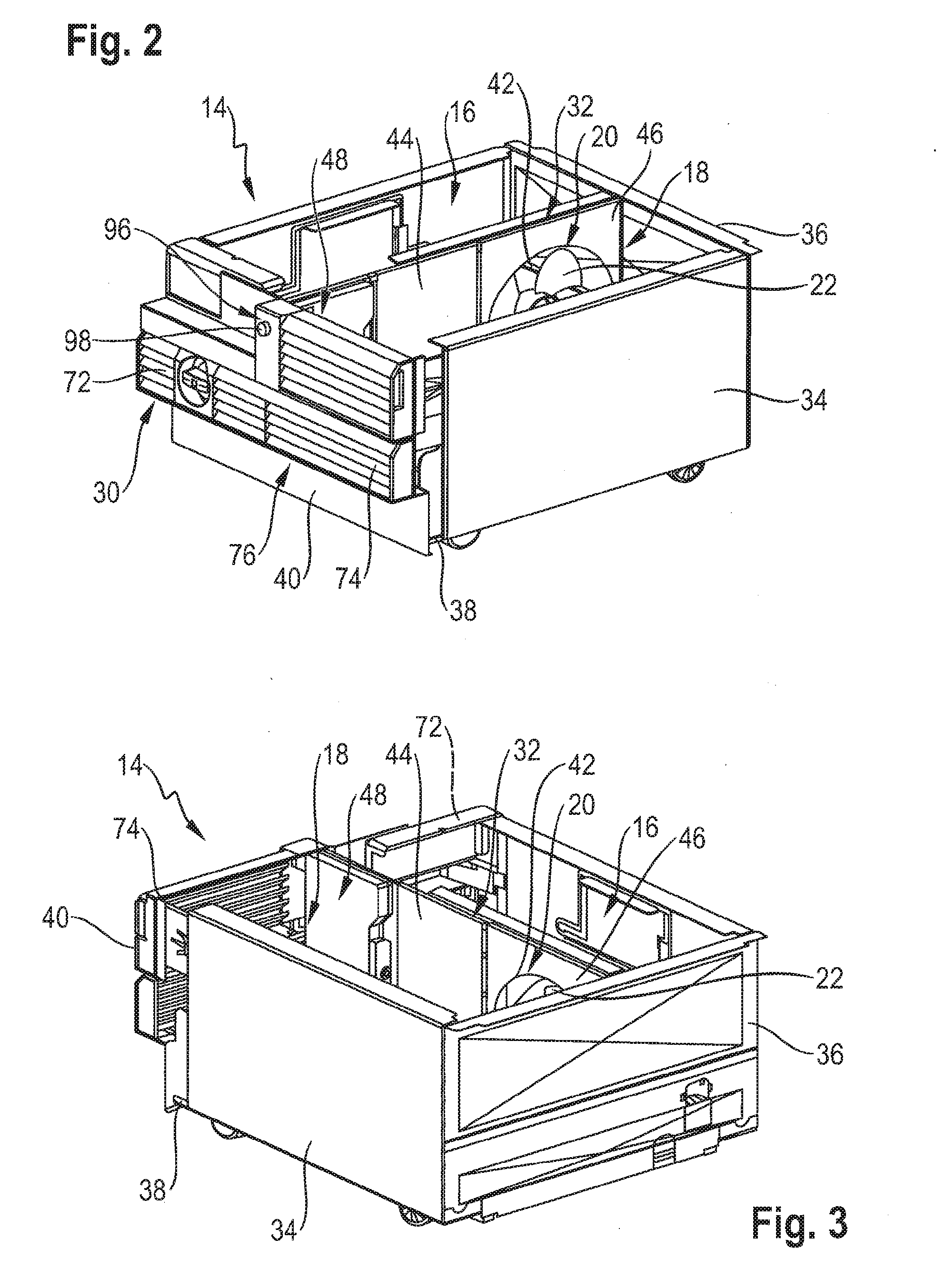
[0029] FIGS. 2, 3 a portion of the home appliance device, comprising a machine compartment, in various perspective views,
[0030] FIGS. 4, 5 a portion of the home appliance device, comprising a refrigerant cycle, in various views,
[0031] FIGS. 6, 7 a portion of the home appliance device, comprising a divisional wall section, an opening device and a cover unit, in different views and
[0032] FIGS. 8, 9 the cover unit in different views,
[0033] FIG. 1 shows a home appliance 62 comprising a home appliance device in a schematic front view. The home appliance 62 is embodied as a refrigerator. The home appliance 62 could further be embodied as a climate cabinet, an ice-box, a freezer, a refrigerator-freezer combination and/or a wine cooler.
[0034] The home appliance device comprises a housing 64. The home appliance device comprises a storage compartment 68. The storage compartment 68 is configured for storing victuals. The storage compartment 68 is arranged inside the housing 64. The home appliance device comprises a door 50. For closing the storage compartment 12, the door 50 comprises a door leaf 70. Further, the home appliance device comprises a drawer 52. The drawer 52 is configured for storing victuals inside the storage compartment 68.
[0035] The home appliance device comprises a machine compartment 14, which is arranged inside the housing 64. In an installation position of the home appliance device, the machine compartment 14 is positioned below the storage compartment 68. Alternatively or additionally the machine compartment 14 could be positioned on top of the storage compartment 68.
[0036] FIGS. 2 and 3 show the machine compartment 14 in various perspective views. The machine compartment 14 is delimited from five sides by wall sections 34, 36, 38, 40. The machine compartment 14 comprises two lateral wall sections 34. The two lateral wall sections 34 delimit the machine compartment 14 from opposite sides. The machine compartment 14 comprises a rear wall section 36. The machine compartment 14 comprises a bottom wall section 38. The machine compartment 14 comprises a front wall section 40. The storage compartment 68 delimits the machine compartment 14 from a sixth side, in particular an upper side. Alternatively or additionally, the machine compartment 14 may comprise an upper wall section which delimits the sixth side.
[0037] The front wall section 40 comprises an air inlet vent 72. Further the front wall section 40 comprises an air outlet vent 74. The air inlet vent 72 and the air outlet vent 74 are arranged side by side. The air inlet vent 72 and the air outlet vent 74 are implemented at least substantially lamellar. Alternatively or additionally other wall sections of the machine compartment 14 such as the rear wall section 36 and/or the lateral wall sections 34 may comprise an air inlet vent and/or an air outlet vent.
[0038] The machine compartment 14 comprises two sub-compartments 16, 18. The machine compartment 14 comprises a first sub-compartment 16. The machine compartment 14 comprises a second sub-compartment 18. The second sub-compartment 18 is embodied separate from the first sub-compartment 16. The first sub-compartment 16 and the second sub-compartment 18 are arranged side by side. The first sub-compartment 16 and the second sub-compartment 18 are of at least substantially equal size.
[0039] The first sub-compartment 16 comprises a fresh-air entrance 30. The fresh-air entrance 30 is embodied by the air inlet vent 72. The second sub-compartment 18 comprises a heated-air exit 76. The heated-air exit 76 is embodied by the air outlet vent 74.
[0040] The machine compartment 14 comprises a divisional wall section 32. The wall sections 32, 34, 36, 38, 40 are at least partly fixable to each other by a fixing unit 78. The fixing unit 78 comprises at least one guiding element 80 configured for attaching at least the wall sections 32, 34, 36, 38, 40 to each other. The guiding element 80 is embodied as a rail. In the present case the fixing 78 unit comprises at least one guiding element 80 for each wall section 32, 34, 36, 38, 40. For example, the divisional wall section 32 is fixed to the bottom wall section 38 by the guiding element 80. The divisional wall section 32 is configured for dividing the machine compartment 14 into the first sub-compartment 16 and the second sub-compartment 18. The divisional wall section 32 separates the second sub-compartment 18 from the first sub-compartment 16. The divisional wall section 32 extends from the rear wall section 36 up to the front wall section 40. The divisional wall section 32 comprises a first wall section 44. The first wall section 44 is situated in a vicinity of the front wall section 40. The divisional wall section 32 comprises a second wall section 46. The second wall section 46 is situated in a vicinity of the rear wall section 36.
[0041] The home appliance device comprises an airflow unit 20. The airflow unit 20 is configured for sucking fresh air into the first sub-compartment 16, in particular through the fresh-air entrance 30. The airflow unit 20 is further configured for transporting air from the first sub-compartment 16 to the second sub-compartment 18. The airflow unit 20 is configured for discharging heated air out of the second sub-compartment 18, in particular through the heated-air exit 76. By means of the airflow unit 20 the second sub-compartment 18 is kept at least substantially warmer than the first sub-compartment 16. In operation the airflow unit 20 substantially prevents air from entering the first sub-compartment 16 from the second sub-compartment 18. The airflow unit 20 comprises a fan 22. The fan 22 is configured for implementing an airflow from the first sub-compartment 16 towards the second sub-compartment 18. The divisional wall section 32, in particular the second wall section 46, is provided with an aperture 42. The aperture 42 is part of the airflow unit 20. The aperture 42 allows an airflow between the first sub-compartment 16 and second sub-compartment 18. The aperture 42 is embodied as a frame for the fan 22. The airflow unit 20 further comprises a fan housing, in which the fan 22 is accommodated. Alternatively or additionally, the aperture 42 can be embodied as the fan housing.
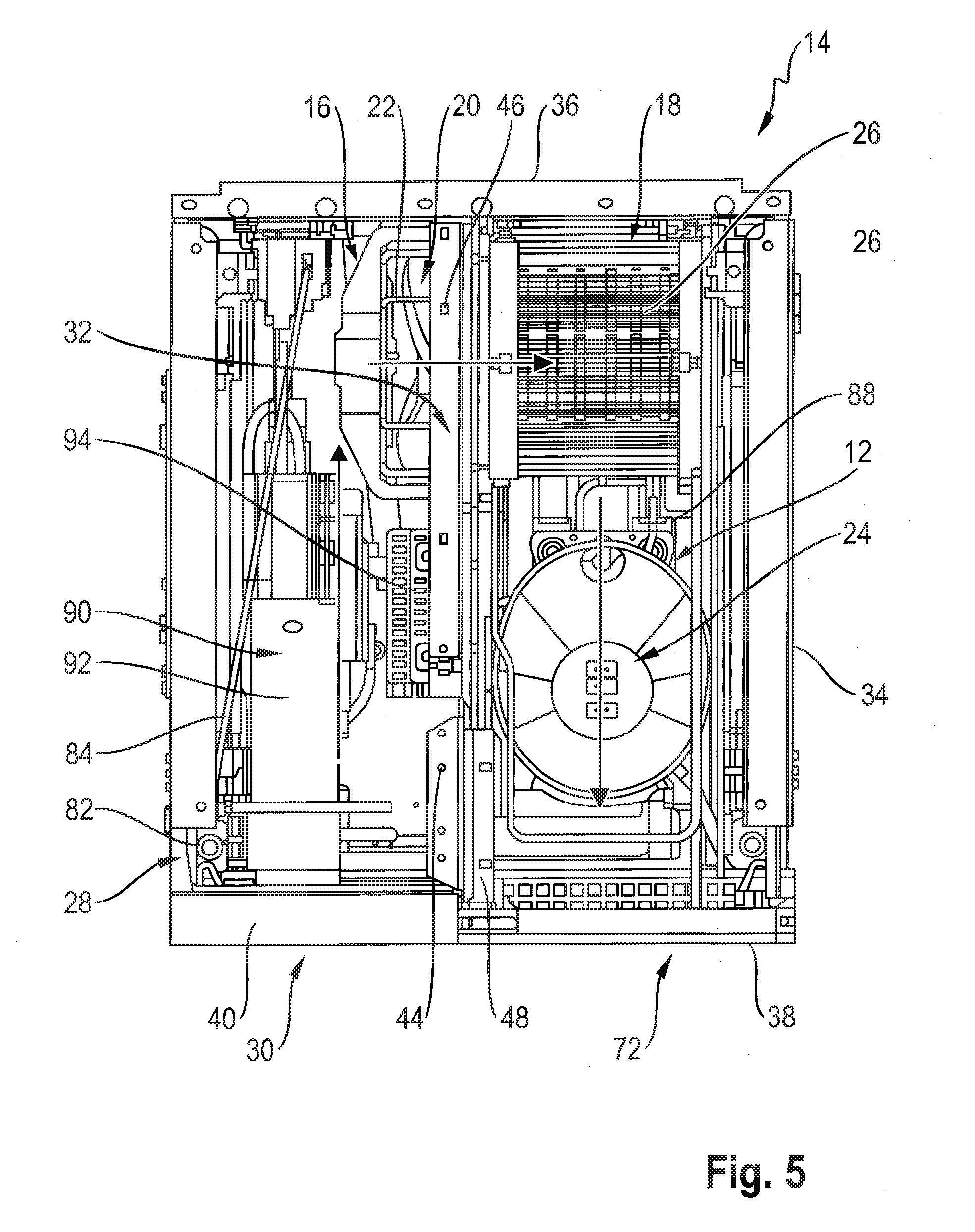
[0042] FIGS. 4 and 5 show a portion of the home appliance device, comprising a refrigerant cycle 10 of the home appliance device, in a perspective view and a top view. The refrigerant cycle 10 comprises a refrigerant. The refrigerant cycle 10 is at least partly, preferably mostly, arranged inside the machine compartment 14. The refrigerant cycle 10 comprises a high-pressure side and a low-pressure side. The refrigerant cycle 10 comprises a compressor 24. The high-pressure side starts at the compressor 24. The compressor 24 is part of a heat generating unit 12 of the home appliance device. The refrigerant enters the compressor 24 as a super-heated gas. A pressure and a temperature of refrigerant are increased by the compressor 24. An enthalpy of the refrigerant rises as a result of compression. The refrigerant cycle 10 further comprises a condenser 26. The condenser 26 is connected to the compressor 24. In the condenser 26, the refrigerant undergoes a phase change. The super-heated gas condenses into a sub-cooled liquid. The refrigerant cycle 10 further comprises a dryer 82. The dryer 82 is part of a refrigerant unit 86 of the home appliance device. The dryer 82 is connected to the condenser 26. The dryer 86 is configured for removing water vapor from the refrigerant. The refrigerant cycle 10 comprises an expansion device 28. The expansion device 28 is part of the refrigerant unit 86. The expansion device 28 is connected to the dryer 82. The expansion device 28 comprises a capillary tube 84. Additionally or alternatively the expansion device 28 may comprise an expansion valve. The capillary tube 84 has a smaller diameter than every other tube of the refrigerant cycle 10. The capillary tube 84 is configured as a metering device, which preferably restricts a flow of the refrigerant. At the end of the capillary tube 84, the high-pressure side ends and the low-pressure side starts. The refrigerant leaves the expansion device 28 through an expansion point. In the expansion point, a diameter of the capillary tube 84 is increased. The refrigerant cycle 10 comprises an evaporator. The refrigerant enters the evaporator. While passing through the evaporator the sub-cooled refrigerant liquid undergoes a phase change from a sub-cooled liquid to a super-heated gas. The refrigerant cycle 10 comprises a suction tube. The suction tube connects the evaporator to the compressor 24. Further the refrigerant cycle 10 comprises a heat exchanger. The heat exchanger is implemented by welding the capillary tube 84 and the suction tube together. Via a heat exchange through the heat exchanger after the evaporator, the refrigerant is converted into a super-heated gas before reentering the compressor 24. Furthermore, via the heat exchanger the refrigerant is converted into a sub-cooled liquid before entering the expansion device 28.
[0043] The suction tube connecting the evaporator and the compressor 24 is at least partly arranged inside the second compartment 18. The compressor 24 is arranged inside the second sub-compartment 18. The compressor 24 is arranged aerodynamically downstream of the airflow unit 20. The compressor 24 is arranged in a vicinity of the heated-air exit 76. The condenser 26 is arranged inside the second compartment 18. The condenser 26 is arranged aerodynamically downstream of the airflow unit 20. The condenser 26 is arranged in a vicinity of the airflow unit 20, and in particular of the aperture 42 of the divisional wall section 32. The condenser 26 is arranged aerodynamically upstream of the compressor 24. The expansion device 28, in particular the capillary tube 84 and preferably the dryer 82, are arranged inside the first sub-compartment 16. The expansion device 82, in particular the capillary tube 84 and preferably the dryer 82, are arranged aerodynamically upstream of the airflow unit 20. The expansion device 82, in particular the capillary tube 84 and preferably the dryer 82, are positioned in a vicinity of the fresh-air entrance 30. The expansion device 28, in particular the capillary tube 84 and preferably the dryer 82, are configured for getting into direct contact with the fresh air upon suction thereof. The evaporator is preferably arranged in a vicinity of the storage compartment 68.
[0044] The home appliance device further comprises an evaporation tray 88. The evaporation tray 88 is configured for collecting condensed water from the storage compartment 68. The evaporation tray 88 is arranged aerodynamically downstream of the airflow unit 30. The evaporation tray 88 is configured for evaporating the condensed water. The evaporation tray 88 is arranged inside the second sub-compartment 18. Preferably the evaporation tray 88 is thermally coupled to the refrigerant cycle 10, in particular to the compressor 24. The evaporation tray 88 is arranged between the compressor 24 and the condenser 26.
[0045] The home appliance device further comprises a water line 90 preferably configured for cooling tap water. The water line 90 comprises in particular a water valve 92. The water line 90, in particular the water valve 92, is at least partly arranged inside the first sub-compartment 16. The water line 90, in particular the water valve 92, is at least partly arranged aerodynamically upstream of the airflow unit 20.
[0046] The home appliance device further comprises a control unit 94. The control unit 94 is configured for controlling and preferably for feedback-controlling at least the refrigerant cycle 10, preferably the compressor 24. The control unit 94 is arranged inside the first sub-compartment 16. The control unit 94 is attached to the divisional wall section 32, in particular to the first wall section 44 of the divisional wall section 32. The control unit 94 is attached to a side of the divisional wall section 32, which faces the first sub-compartment 16. In addition the control unit 94 serves as a power supply unit. Alternatively or additionally the home appliance device may comprise a separate power supply unit.
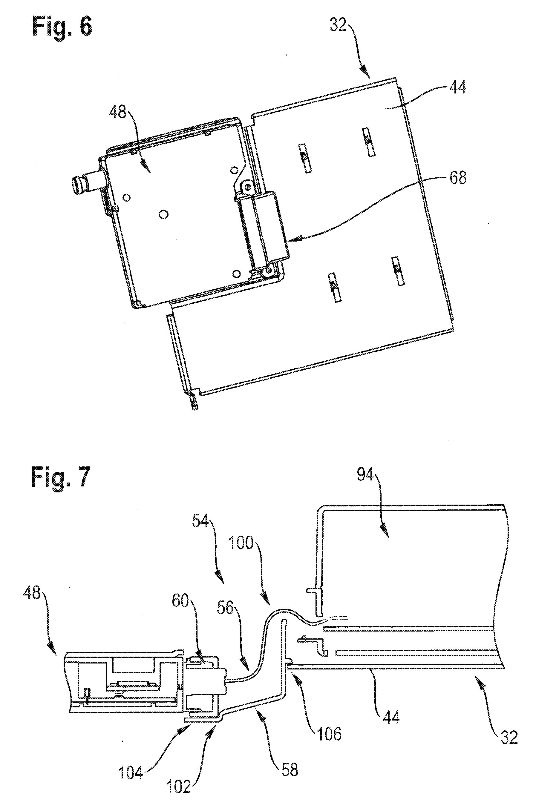
[0047] FIGS. 6 and 7 show a portion of the home appliance device, comprising the divisional wall 32 and an opening device 48 of the home appliance device, in various views. The opening device 48 is configured for opening a closed door 50, in particular a closed door leaf 70 of the door 50 (see FIG. 1). Alternatively or additionally the opening device 48 may be configured for opening a closed drawer 52, in particular a bottom drawer.
[0048] The opening device 48 is at least partly arranged in the machine compartment 14 (see FIGS. 2 to 4). The opening device 48 is arranged at least substantially centrally inside the machine compartment 14. The opening device 48 extends at least partly through the front wall section 40 of the machine compartment 14 (see FIG. 2). The front wall section 40 comprises in particular a pass-through recess 96 for the opening device 48. The opening device 48 comprises a plunger 98. The plunger 98 is movable. The plunger 98 is configured for contacting the door 50. Alternatively or additionally the plunger 98 may be configured for contacting the drawer 52. The plunger 98 is arranged at least partly inside the pass-through recess 96 of the front wall section 40. The opening device 48 is arranged inside the second sub-compartment 18. The opening device 48 is attached to the divisional wall section 32, in particular to the first wall section 44 of the divisional wall section 32. The opening device 48 is attached to a side of the divisional wall section 32 which faces the second sub-compartment 18.
[0049] The home appliance device further comprises an electrical connection unit 54. The electrical connection unit 54 is configured for electrically connecting the opening device 48 with a further unit. The further unit is arranged in the first sub-compartment 16. In this case the further unit is the control unit 94. Alternatively or additionally the further unit may be a separate power supply unit of the home appliance device. The divisional wall section 32 comprises a cabling recess 56. The divisional wall section 32 comprises the cabling recess 56 in particular in its first wall section 44. The cabling recess 56 is configured for at least partly passing through the electrical connection unit 45. The electrical connection unit 54 comprises a connector plug 60. In an installation position, the opening device 48 connects to the connector plug 60. The electrical connection unit 54 further comprises a cabling harness 100. The cabling harness 100 connects the connector plug 60 to the control unit 94. The cabling harness 100 passes through the cabling recess 54.
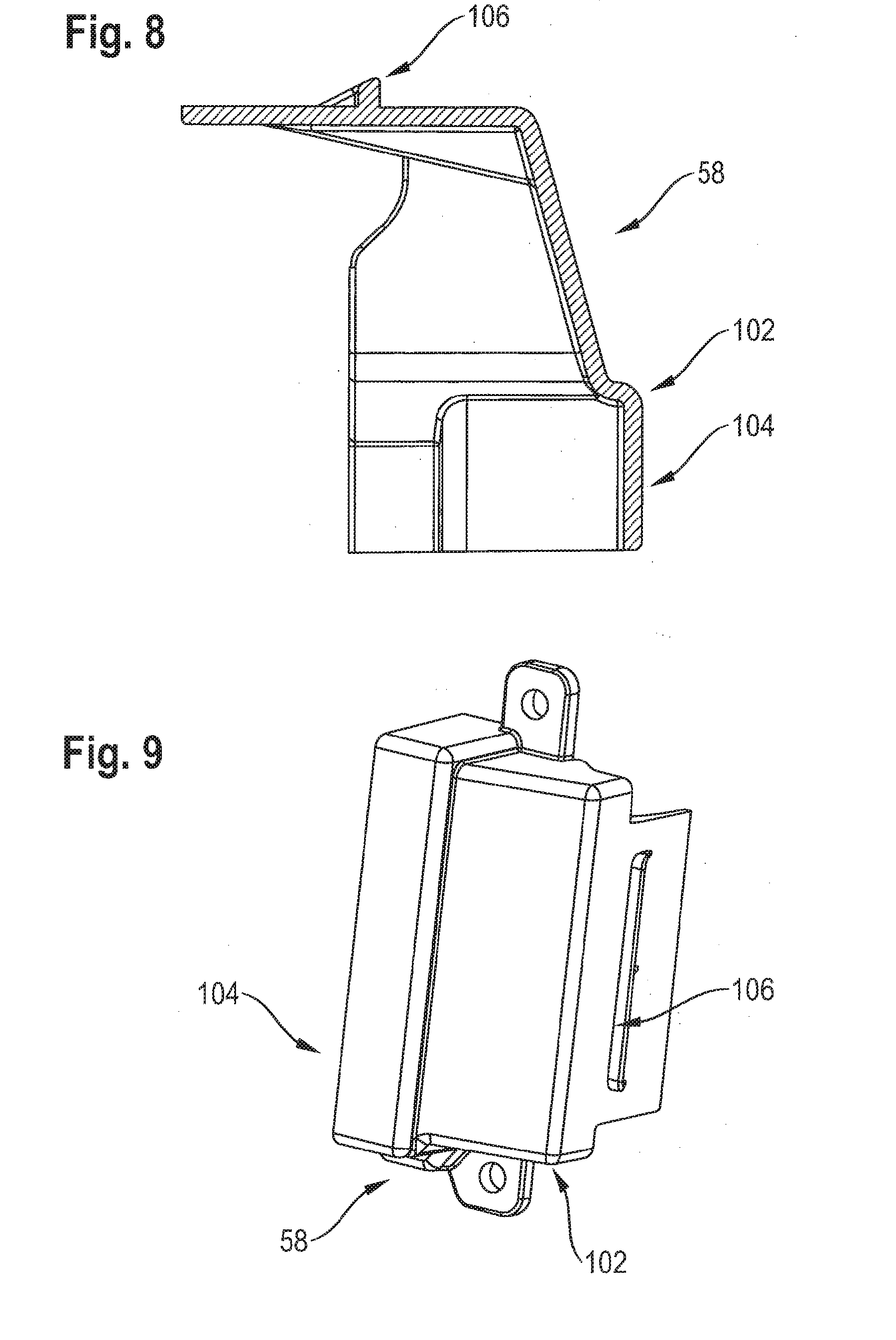
[0050] FIGS. 8 and 9 show of cover unit 58 of the home appliance device. The cover unit 58 is implemented integrally. The cover unit 58 may be made of plastic or metal, in particular sheet metal. The cover unit 58 is configured for at least substantially preventing airflow from the second sub-compartment 18 into the first sub-compartment 16 through the cabling recess 56. The cover unit 58 is attachable to the divisional wall section 32, in particular to the first wall section 44 of the divisional wall section 32. The cover unit 58 is attachable to the divisional wall section 32 by two screws. The cover unit 58 at least partly encompasses the connector plug 60 of the electrical connection unit 54. In an installation position the cover unit 58 comprises a locking element 102. The locking element 102 is a form fit element. The locking element 102 is shaped at least partly corresponding to the electrical connector unit 54, in particular to the connector plug 60. The locking element 102 is in particular embodied as a locking corner.
[0051] The cover unit 58 is configured for sealing the cabling recess 56. The cover unit 58 comprises a sealing element 104. The sealing element 104 at least partly overlaps with the electrical connector unit 54, in particular with the connector plug 60, preferably in a main extension direction of the divisional wall section 32. The sealing element 104 is implemented as a bent portion of the cover unit 58. The cover unit 58 comprises a further sealing element 106. The further sealing element 106 at least partly overlaps with the divisional wall section 32, preferably in a main extension direction of the divisional wall section 32. The further sealing element 106 is implemented as a protrusion of the cover unit 58.
REFERENCE NUMERALS
[0052] 10 refrigerant cycle [0053] 12 heat generating unit [0054] 14 machine compartment [0055] 16 first sub-compartment [0056] 18 second sub-compartment [0057] 20 airflow unit [0058] 22 fan [0059] 24 compressor [0060] 26 condenser [0061] 28 expansion device [0062] 30 fresh-air entrance [0063] 32 divisional wall section [0064] 34 lateral wall section [0065] 36 rear wall section [0066] 38 bottom wall section [0067] 40 front wall section [0068] 42 aperture [0069] 44 first wall section [0070] 46 second wall section [0071] 48 opening device [0072] 50 door [0073] 52 drawer [0074] 54 electrical connection unit [0075] 56 cabling recess [0076] 58 cover unit [0077] 60 connector plug [0078] 62 home appliance [0079] 64 housing [0080] 68 storage compartment [0081] 70 door leaf [0082] 72 air inlet vent [0083] 74 air outlet vent [0084] 76 heated-air exit [0085] 78 fixing unit [0086] 80 guiding element [0087] 82 dryer [0088] 84 capillary tube [0089] 86 refrigerant unit [0090] 88 evaporation tray [0091] 90 water line [0092] 92 water valve [0093] 94 control unit [0094] 96 pass-through recess [0095] 98 plunger [0096] 100 cabling harness [0097] 102 locking element [0098] 104 sealing element [0099] 106 further sealing element
* * * * *
D00000
D00001
D00002
D00003
D00004
D00005
D00006
XML
uspto.report is an independent third-party trademark research tool that is not affiliated, endorsed, or sponsored by the United States Patent and Trademark Office (USPTO) or any other governmental organization. The information provided by uspto.report is based on publicly available data at the time of writing and is intended for informational purposes only.
While we strive to provide accurate and up-to-date information, we do not guarantee the accuracy, completeness, reliability, or suitability of the information displayed on this site. The use of this site is at your own risk. Any reliance you place on such information is therefore strictly at your own risk.
All official trademark data, including owner information, should be verified by visiting the official USPTO website at www.uspto.gov. This site is not intended to replace professional legal advice and should not be used as a substitute for consulting with a legal professional who is knowledgeable about trademark law.