Centrifugal Compressor With Leakage-free Diffuser Blades And Method Of Assembling A Centrifugal Compressor
PANARA; Daniele ; et al.
U.S. patent application number 16/079475 was filed with the patent office on 2019-02-14 for centrifugal compressor with leakage-free diffuser blades and method of assembling a centrifugal compressor. The applicant listed for this patent is Nuovo Pignone Tecnologie Srl. Invention is credited to Daniele PANARA, Emanuele RIZZO.
| Application Number | 20190048891 16/079475 |
| Document ID | / |
| Family ID | 56203834 |
| Filed Date | 2019-02-14 |


| United States Patent Application | 20190048891 |
| Kind Code | A1 |
| PANARA; Daniele ; et al. | February 14, 2019 |
CENTRIFUGAL COMPRESSOR WITH LEAKAGE-FREE DIFFUSER BLADES AND METHOD OF ASSEMBLING A CENTRIFUGAL COMPRESSOR
Abstract
A centrifugal compressor includes a rotor with a plurality of impellers and a stator with at least a first diaphragm, a second diaphragm, a diffuser, and a plurality of diffuser blades inside the diffuser; each diffuser blade has a tip portion, a base portion and an airfoil portion; and are located between the downstream portion of the first diaphragm and the upstream portion of the second diaphragm; the base portion of the diffuser blades is integrated in or mounted to the upstream portion of the second diaphragm, and the tip portion of the diffuser blades abuts against the downstream portion of the first diaphragm; alternatively, the base portion of the diffuser blades is integrated in or mounted to the downstream portion of the first diaphragm, and the tip portion of the diffuser blades abuts against the upstream portion of the second diaphragm.
| Inventors: | PANARA; Daniele; (Florence, IT) ; RIZZO; Emanuele; (Firenze, IT) | ||||||||||
| Applicant: |
|
||||||||||
|---|---|---|---|---|---|---|---|---|---|---|---|
| Family ID: | 56203834 | ||||||||||
| Appl. No.: | 16/079475 | ||||||||||
| Filed: | March 20, 2017 | ||||||||||
| PCT Filed: | March 20, 2017 | ||||||||||
| PCT NO: | PCT/EP2017/056499 | ||||||||||
| 371 Date: | August 23, 2018 |
| Current U.S. Class: | 1/1 |
| Current CPC Class: | F04D 1/066 20130101; F04D 29/624 20130101; F04D 29/462 20130101; F04D 17/122 20130101; F04D 17/10 20130101; F04D 29/444 20130101 |
| International Class: | F04D 29/44 20060101 F04D029/44; F04D 17/10 20060101 F04D017/10; F04D 29/62 20060101 F04D029/62 |
Foreign Application Data
| Date | Code | Application Number |
|---|---|---|
| Mar 21, 2016 | IT | 102016000029251 |
Claims
1. A centrifugal compressor for a fluid, comprising a rotor with a plurality of impellers and a stator with at least a first diaphragm, a second diaphragm downstream the first diaphragm, a diffuser defined between a shroud side of a downstream portion of the first diaphragm and a hub side of a upstream portion of the second diaphragm, and a plurality of diffuser blades inside the diffuser, each diffuser blade having a tip portion, a base portion and an airfoil portion between the base portion and the tip portion, wherein the diffuser blades are located between the downstream portion of the first diaphragm and the upstream portion of the second diaphragm, wherein the base portion of the diffuser blades is integrated in or mounted directly or indirectly to the upstream portion of the second diaphragm so to avoid fluid flow between the base portion and the hub side of the upstream portion, and the tip portion of the diffuser blades abuts against the downstream portion of the first diaphragm so to avoid fluid flow between the tip portion and the shroud side of the downstream portion or wherein the base portion of the diffuser blades is integrated in or mounted directly or indirectly to the downstream portion of the first diaphragm so to avoid fluid flow between the base portion and the shroud side of the downstream portion, and the tip portion of the diffuser blades abuts against the upstream portion of the second diaphragm so to avoid fluid flow between the tip portion and the hub side of the upstream portion.
2. The centrifugal compressor of claim 1, wherein the tip portion of each diffuser blade of the plurality is movable, resiliently movable, with respect to the first diaphragm or the second diaphragm whereto it is mounted.
3. The centrifugal compressor of claim 1, wherein each diffuser blade of plurality comprises a first platform adjacent to the base portion and a spring acting on the first platform.
4. The centrifugal compressor of claim 1, wherein each diffuser blade of the plurality comprises a second platform and the spring is located between the first platform and the second platform and acts on them.
5. The centrifugal compressor of claim 1, wherein at least the base portion or the airfoil portion or the tip portion of each diffuser blade of the plurality is made of elastic material.
6. The centrifugal compressor of claim 1, wherein the base portion and the airfoil portion and the tip portion of each diffuser blade of the plurality is made of elastic material, the same elastic material.
7. The centrifugal compressor of claim 1, wherein each diffuser blade of the plurality comprises a snap mount for mounting it to the first diaphragm or the second diaphragm.
8. A method of assembling a centrifugal compressor, wherein: a plurality of half-diaphragms are bundled together; A) a half-casing or half-counter-casing is lowered on the bundle; B) the plurality of half-diaphragms are loosened inside said half-casing or half-counter-casing; and C) the plurality of half-diaphragms are fixed to the half-casing or half-counter-casing.
9. The method of claim 8, wherein: the half-casing or half-counter-casing with half-diaphragms inside is turned upside down; and D) a rotor of the centrifugal compressor is lowered on the turned half-casing or half-counter-casing with half-diaphragms inside.
10. The method of claim 9, wherein E) a plurality of half-diaphragms are bundled together, F) a half-casing or half-counter-casing is lowered on the bundle G) the plurality of half-diaphragms are loosened inside the half-casing or half-counter-casing, H) the plurality of half-diaphragms are fixed to the half-casing or half-counter-casing, and I) the half-casing or half-counter-casing with half-diaphragms inside is lowered on the assembly.
11. The method of claim 8, wherein diffuser blades are located between adjacent half-diaphragms and wherein the diffuser blades are compressible.
12. The method of claim 11, wherein, one or more diffuser blades is or are compressed during bundling.
13. The method of claim 11, wherein, one or more diffuser blades is or are mounted to half-diaphragms.
Description
FIELD OF THE INVENTION
[0001] Embodiments of the subject matter disclosed herein correspond to centrifugal compressors with leakage-free diffuser blades and methods of assembling centrifugal compressors.
BACKGROUND OF THE INVENTION
[0002] Centrifugal compressors usually have one or more diffusers; a diffuser is a (stationary) channel or multi-channel that receives a flow of a working fluid when it exits a (rotary) impeller of a compressor; a diffuser may comprise diffuser blades; a diffuser blade is fixed to a diaphragm of the compressor by shrink fitting or by friction fitting or by screwing or by welding or because it is integral with the diaphragm.
[0003] At least in the field of Oil & Gas, it is common practice to start assembling of a compressor by: [0004] providing a half-casing or a half-counter-casing of the compressor, [0005] lowering the half-diaphragms of the compressor, one by one, into the half-casing or half-counter-casing and fixing them, one by one, to it, [0006] lowering the rotor of the compressor on the half-casing or half-counter-casing with half-diaphragm already inside.
[0007] Due to such assembling method, when the half-diaphragms comprise diffuser blades, there must be a clearance between the tips of each diffuser blade and the surfaces of the diaphragms facing the tips.
[0008] In fact, friction or interference between the diffuser blades and the diaphragms should be avoided during assembling of the compressor.
[0009] Furthermore, the lowering of the half-diaphragms should be precise in order to avoid damages to the diffuser blades and/or the diaphragms due to contact between the diffuser blades and the diaphragms.
[0010] Such gaps between the tips of each diffuser blade and the surfaces of the diaphragms facing the tips are disadvantageous as they cause secondary effects that are related to the flow of working fluid between the tips and such surfaces during operation of the compressor.
[0011] Ideally, all the working fluid of the compressor should flow around the diffuser blades guided by the airfoil portions of the diffuser blades.
SUMMARY OF INVENTION
[0012] Therefore, there is a general need for improving turbomachines and their assembling methods.
[0013] This need is particularly high for centrifugal compressors such as those used in the field of "Oil & Gas", i.e. machines used in plants for exploration, production, storage, refinement and distribution of oil and/or gas.
[0014] First embodiments of the subject matter disclosed herein relate to centrifugal compressors.
[0015] According to such first embodiments, the centrifugal compressor comprises a rotor with a plurality of impellers and a stator with at least a first diaphragm, a second diaphragm downstream said first diaphragm, a diffuser defined between a shroud side of a downstream portion of said first diaphragm and a hub side of a upstream portion of said second diaphragm, and a plurality of diffuser blades inside said diffuser; each diffuser blade has a tip portion, a base portion and an airfoil portion between the base portion and the tip portion; said diffuser blades are located between said downstream portion of said first diaphragm and said upstream portion of said second diaphragm; the base portion of said diffuser blades is integrated in or mounted directly or indirectly to said upstream portion of said second diaphragm so to avoid fluid flow between said base portion and said hub side of said upstream portion, and the tip portion of said diffuser blades abuts against said downstream portion of said first diaphragm so to avoid fluid flow between said tip portion and said shroud side of said downstream portion; alternatively, the base portion of said diffuser blades is integrated in or mounted directly or indirectly to said downstream portion of said first diaphragm so to avoid fluid flow between said base portion and said shroud side of said downstream portion, and the tip portion of said diffuser blades abuts against said upstream portion of said second diaphragm so to avoid fluid flow between said tip portion and said hub side of said upstream portion.
[0016] Second embodiments of the subject matter disclosed herein relate to methods of assembling centrifugal compressors.
[0017] According to such second embodiments, the method of assembling a centrifugal compressor provides that: A) a plurality of half-diaphragms are bundled together, B) a half-casing or half-counter-casing is lowered on said bundle, C) said plurality of half-diaphragms are loosened inside said half-casing or half-counter-casing, and D) said plurality of half-diaphragms are fixed to said half-casing or half-counter-casing.
BRIEF DESCRIPTION OF THE DRAWINGS
[0018] The accompanying drawings, which are incorporated herein and constitute an integral part of the present specification, illustrate exemplary embodiments of the present invention and, together with the detailed description, explain these embodiments. In the drawings:
[0019] FIG. 1 shows schematically and partially a cross-section of an embodiment of a centrifugal compressor,
[0020] FIG. 2A shows schematically an embodiment of a diffuser blade as it is used in the centrifugal compressor of FIG. 1,
[0021] FIG. 2B shows schematically an embodiment of a diffuser blade used differently from FIG. 2A,
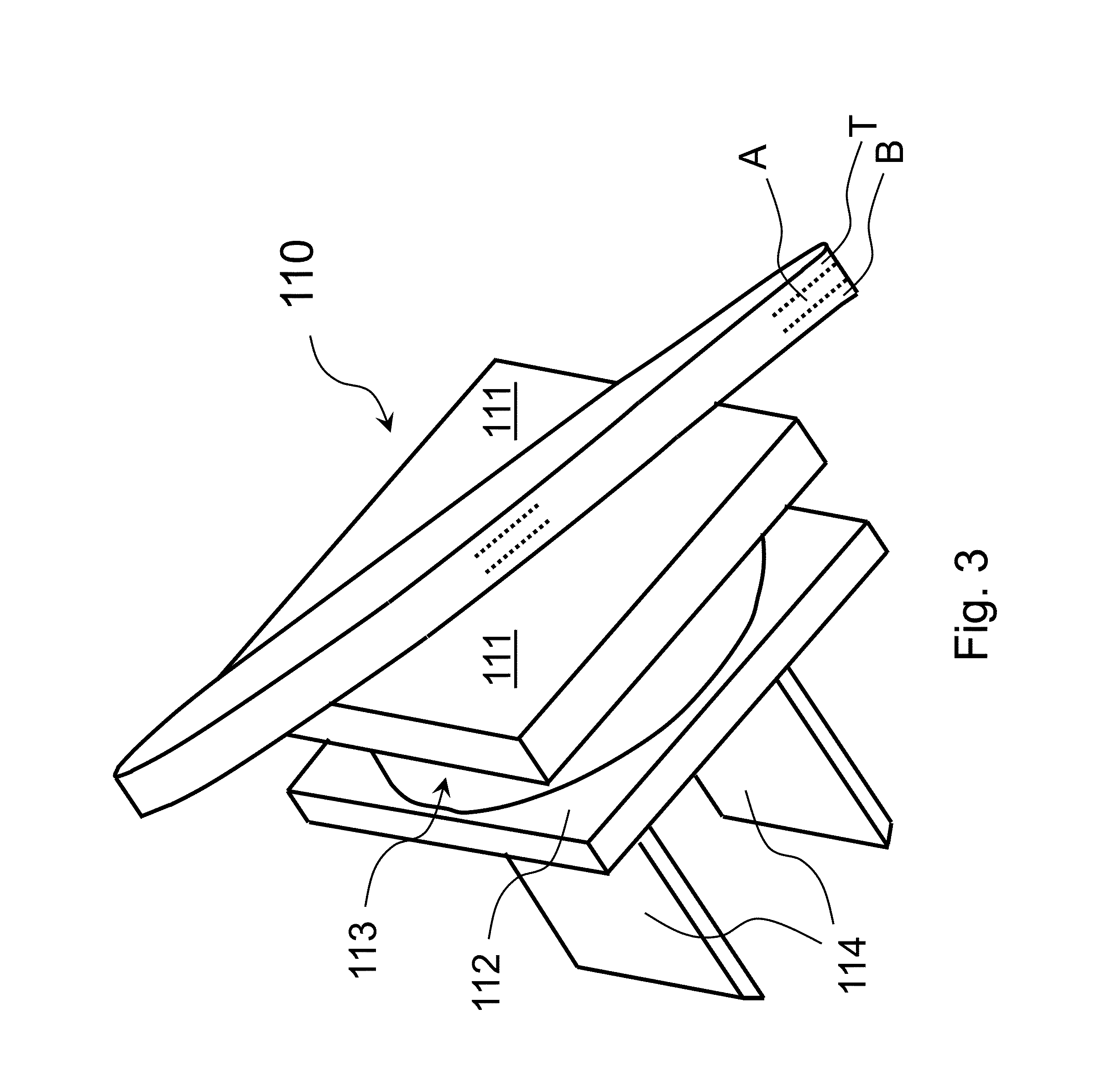
[0022] FIG. 3 shows in detail another embodiment of a diffuser blade of the centrifugal compressor of FIG. 1, and
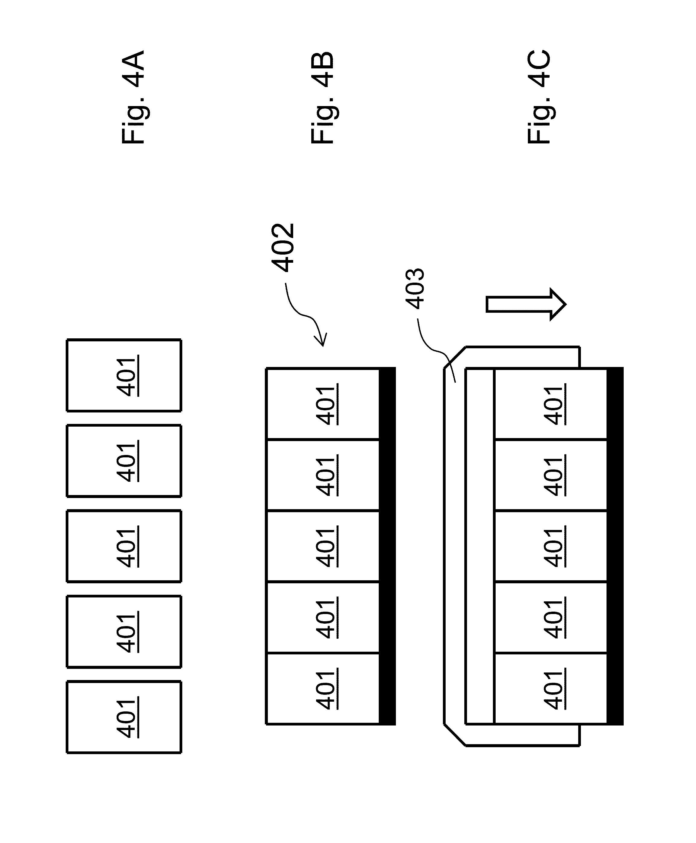
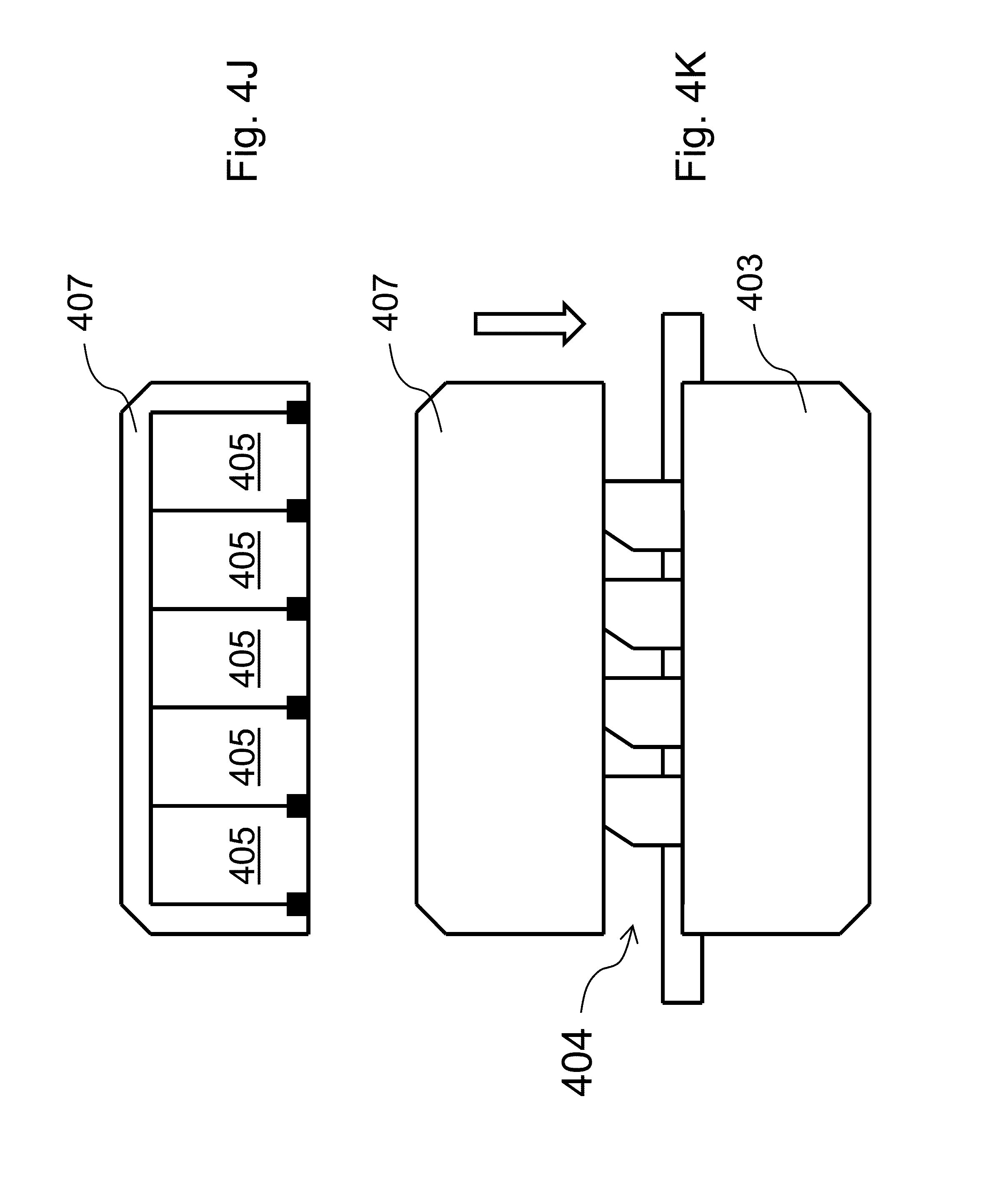
[0023] FIG. 4 comprising FIGS. 4A to 4K shows some steps of an embodiment of a method of assembling a centrifugal compressor.
DETAILED DESCRIPTION
[0024] The following description of exemplary embodiments refers to the accompanying drawings.
[0025] The following description does not limit embodiments of the invention. Instead, the scope of embodiments of the invention is defined by the appended claims.
[0026] Reference throughout the specification to "one embodiment" or "an embodiment" means that a particular feature, structure, or characteristic described in connection with an embodiment is included in at least one embodiment of the subject matter disclosed. Thus, the appearance of the phrases "in one embodiment" or "in an embodiment" in various places throughout the specification is not necessarily referring to the same embodiment. Further, the particular features, structures or characteristics may be combined in any suitable manner in one or more embodiments.
[0027] FIG. 1 shows schematically and partially a cross-section of an embodiment of a centrifugal compressor 100 for compressing a fluid.
[0028] Compressor 100 comprises a stator and a rotor.
[0029] The rotor comprises a shaft 103 and some impellers; FIG. 1 shows only a first centrifugal impeller 104 of a first compression stage and a second centrifugal impeller 105 of a second compression stage; both impellers 104 and 105 are fixed to the shaft 103; the second compression stage immediately follows the first compression stage and both are used for compressing the same fluid; FIG. 1 highlights the hub side 104H and the shroud side 104S of impeller 104.
[0030] The stator comprises a casing 101, a counter casing 102 placed inside the casing 101, and some diaphragms; FIG. 1 shows only a first diaphragm and a second diaphragm; such diaphragms consist of a upstream portion and a downstream portion wherein the words "upstream" and "downstream" take the fluid flow direction inside the compressor into account; FIG. 1 shows only the downstream portion 106 of the first diaphragm, the upstream portion 107 of the second diaphragm and the downstream portion 108 of the second diaphragm.
[0031] In FIG. 1, the fluid flows into the impeller 104, then out of the impeller 104, then between the downstream portion 106 and the upstream portion 107, then between the counter casing 102 and the upstream portion 107, then between the upstream portion 107 and the downstream portion 108, then into the impeller 105, then out of the impeller 105.
[0032] Two sets of statory blades are present in the compressor 100: return-channel blades 109 and diffuser blades 110; the blades 109 are located between the upstream portion 107 of the second diaphragm and the downstream portion 108 of the second diaphragm; the blades 110 are located inside the diffuser between the downstream portion 106 (in particular its shroud side 106S) of the first diaphragm and upstream portion 107 (in particular its hub side 107H) of the second diaphragm.
[0033] A diaphragm may consist of a single piece or two distinct pieces fixed to each other or three distinct pieces (i.e. upstream portion, downstream portion and return-channel blades) fixed to each other.
[0034] The diffuser blades will now be described in detail referring to FIG. 1 and FIG. 2A.
[0035] Each diffuser blade 110 has a tip portion 110T, a base portion 110B and an airfoil portion 110A between the base portion 110B and the tip portion 110T.
[0036] According to a first possibility (shown in FIG. 1 and FIG. 2A), the base portion 110B is integrated in or mounted directly or indirectly to the upstream portion 107 so to avoid fluid flow between the base portion 110B and the hub side 107H, and the tip portion 110T abuts against the downstream portion 106 so to avoid fluid flow between the tip portion 110T and the shroud side 106S. It is to be noted that FIG. 2A shows a gap between the tip portion 110T and the shroud side 106S (and a double-headed arrow), but this represents only the fact that the tip portion 110T is not integral with the first diaphragm 106 (and may move). In an embodiment, the whole cross-section of the tip portion at the end of the blade is in contact with the surface (shroud side) of the downstream portion of the first diaphragm. In an embodiment, the whole cross-section of the base portion at the end of the blade is in line with the surface (hub side side) of the upstream portion of the second diaphragm. In an embodiment, the area of the surface (shroud side) of the downstream portion of the first diaphragm is substantially flat, i.e. it is not recessed with respect to other areas of the downstream portion. In an embodiment, the area of the surface (hub side side) of the upstream portion of the second diaphragm is substantially flat, i.e. it is not recessed with respect to other areas of the upstream portion.
[0037] According to a second possibility (shown in FIG. 2B), the base portion 130B of the diffuser blades 130 is integrated in or mounted directly or indirectly to the downstream portion (106 in FIG. 1 and FIG. 2B) of the first diaphragm so to avoid fluid flow between the base portion 130B and the shroud side 106S of the downstream portion 106, and the tip portion 130T of the diffuser blades 130 abuts against the upstream portion (107 in FIG. 1 and FIG. 2B) of the second diaphragm so to avoid fluid flow between the tip portion 130T and the hub side 107H of the upstream portion 107.
[0038] Abutment without substantial friction may be obtained by letting the tip portion of the blades move.
[0039] In the following, reference will be made to the embodiment of FIG. 2A (as well as to FIG. 1); similar considerations apply to the embodiment of FIG. 2B.
[0040] According to a first approach, movement is obtained through a resilient component, for example a spring.
[0041] In this case, the tip portion 110T of each diffuser blade 110 may be movable, more particularly resiliently movable, with respect to the first diaphragm (106 in FIG. 1) or the second diaphragm (107 in FIG. 1) whereto it is mounted (see e.g. FIG. 2A and the double-headed arrow).
[0042] The possibility of movement may be provided by a spring located for example below the surface of the first diaphragm (106 in FIG. 1) or the second diaphragm (107 in FIG. 1) whereto the blade is mounted.
[0043] According to a second approach, movement is obtained through a resilient portion of the blade.
[0044] In this case, at least the base portion 110B or the airfoil portion 110A or the tip portion 110T of each diffuser blade 110 may be made of elastic material; one or more other portions of the diffuser blade may be made of elastic material.
[0045] According to a specific embodiment, the base portion 110B and the airfoil portion 110A and the tip portion 110T of each diffuser blade 110 is made of elastic material, more particularly the same elastic material.
[0046] The first approach and the second approach may also be combined.
[0047] The above-mentioned movement may be in the range of e.g. 0.2-0.4 mm.
[0048] According to the first approach, a spring may be used having a spring constant in the range of e.g. 0.3-3.0 10.sup.6 N/m.
[0049] According to the second approach, an elastic material may be used having a Young's Modulus in the range of e.g. 0.1-10.0 GPa. Suitable materials may be for example polymers (such as PolyEther Ether Ketone i.e. "PEEK"), including i.a. polyethylenes, and elastomers. For example, the airfoil portion of the diffuser blades may be made of e.g. aluminum and the tip portion of the diffuser blades may be made of e.g. PEEK.
[0050] It is to be noted that the diffuser blades are exposed to quite hot (for example at 100-300.degree. C.) and quite corrosive substances (for example a mixture of hydrocarbons); therefore, their materials should be chosen accordingly.
[0051] In any case (i.e. first approach and/or second approach), each diffuser blade 110 may comprise a snap mount for mounting it to the first diaphragm (106 in FIG. 1) or the second diaphragm (107 in FIG. 1).
[0052] FIG. 3 shows a specific embodiment of a diffuser blade 110. The base portion 110B, the airfoil portion 110A and the tip portion 110T are very thin. The blade 110 comprises a first platform 111 adjacent to the base portion 110B, a second platform 112 and a spring 113 that is located between the first platform 111 and the second platform 112 and acts on them. The blade 110 comprises a snap mount 114 for mounting it to the first diaphragm (106 in FIG. 1) or the second diaphragm (107 in FIG. 1); the snap mount 114 may comprise two elastic tongues. The platforms 11 and 112, the spring 113 and the mount 114 are designed to be completely inserted into a blind hole of a diaphragm; the outer surface of the platform 111 will be approximately (depending on the compression of the spring 113) in line with the surface of the diaphragm.
[0053] Thanks to diffuser blades identical or similar to those just described, other assembling methods may be used.
[0054] An embodiment of a method of assembling a centrifugal compressor will be described in the following with the aid of FIG. 4.
[0055] According to this embodiment, diffuser blades are located between adjacent half-diaphragms of the compressor; these diffuser blades are compressible.
[0056] Initially: [0057] a plurality of half-diaphragms 401 (see FIG. 4A) are bundled together (see FIG. 4B the single black stripe at the bottom represents a link or bond between them); the bundling action results in a light compression of the diffuser blades; [0058] a half-casing 403 or half-counter-casing is lowered on the bundle 402 (see FIG. 4C); [0059] the plurality of half-diaphragms 401 are loosened inside the half-casing 403 or half-counter-casing (see FIG. 4D--the single black stripe at the bottom is no longer present as the link or bond between is released); the diffuser blades rearrange slightly inside the half-casing; and
[0060] the plurality of half-diaphragms 401 are fixed to the half-casing 403 or half-counter-casing (see FIG. 4D--several short black stripes at the bottom represent fixing devices).
[0061] Due to the light compression of the diffuser blades, each half-diaphragm reduces its width (or axial size) somewhat, for example from a minimum of 0.2 mm to a maximum of 0.4 mm. Depending on the construction of the diffuser blade, such reduction in size derives from a compression of a resilient component of the diffuser blade and/or of a resilient portion of the diffuser blade.
[0062] Afterwards, after step D: [0063] the half-casing 403 or half-counter-casing with half-diaphragms 401 inside is turned upside down (see FIG. 4E); and [0064] a rotor 404 of the centrifugal compressor is lowered on the turned half-casing 403 or half-counter-casing with half-diaphragms 401 inside (see FIG. 4F); bearings or half-bearings keep the rotor in position.
[0065] Finally, after step F: [0066] a plurality of half-diaphragms 405 (see FIG. 4G) are bundled together (see FIG. 4H--the single black stripe at the bottom represents a link or bond between them); the bundling action results in a light compression of the diffuser blades; [0067] a half-casing 407 or half-counter-casing is lowered on the bundle 406 (see FIG. 4I); [0068] the plurality of half-diaphragms 405 are loosened inside the half-casing 407 or half-counter-casing (see FIG. 4J--the single black stripe at the bottom is no longer present as the link or bond between is released); the diffuser blades rearrange slightly inside the half-casing; [0069] the plurality of half-diaphragms (405) are fixed to said half-casing (407) or half-counter-casing (see FIG. 4J--several short black stripes at the bottom represent fixing devices); and [0070] the half-casing 407 or half-counter-casing with half-diaphragms 405 inside is lowered on the assembly deriving at step F (see FIG. 4K).
[0071] In step A and/or in step G, one or more diffuser blades is or are compressed during bundling.
[0072] Prior to step A and/or prior to step G, one or more diffuser blades is or are mounted to half-diaphragms.
[0073] This written description uses examples to disclose the invention, including the preferred embodiments, and also to enable any person skilled in the art to practice the invention, including making and using any devices or systems and performing any incorporated methods. The patentable scope of the invention is defined by the claims, and may include other examples that occur to those skilled in the art. Such other examples are intended to be within the scope of the claims if they have structural elements that do not differ from the literal language of the claims, or if they include equivalent structural elements with insubstantial differences from the literal languages of the claims.
* * * * *
D00000
D00001
D00002
D00003
D00004
D00005
D00006
XML
uspto.report is an independent third-party trademark research tool that is not affiliated, endorsed, or sponsored by the United States Patent and Trademark Office (USPTO) or any other governmental organization. The information provided by uspto.report is based on publicly available data at the time of writing and is intended for informational purposes only.
While we strive to provide accurate and up-to-date information, we do not guarantee the accuracy, completeness, reliability, or suitability of the information displayed on this site. The use of this site is at your own risk. Any reliance you place on such information is therefore strictly at your own risk.
All official trademark data, including owner information, should be verified by visiting the official USPTO website at www.uspto.gov. This site is not intended to replace professional legal advice and should not be used as a substitute for consulting with a legal professional who is knowledgeable about trademark law.