Anti-gas Lock Electric Submersible Pump
REED; Stewart Darold ; et al.
U.S. patent application number 15/763781 was filed with the patent office on 2019-02-14 for anti-gas lock electric submersible pump. This patent application is currently assigned to HALLIBURTON ENERGY SERVICES, INC.. The applicant listed for this patent is HALLIBURTON ENERGY SERVICES, INC.. Invention is credited to Stewart Darold REED, Dezhi ZHENG.
| Application Number | 20190048886 15/763781 |
| Document ID | / |
| Family ID | 62028165 |
| Filed Date | 2019-02-14 |


| United States Patent Application | 20190048886 |
| Kind Code | A1 |
| REED; Stewart Darold ; et al. | February 14, 2019 |
ANTI-GAS LOCK ELECTRIC SUBMERSIBLE PUMP
Abstract
An electric submersible pump including a housing having a longitudinal axis extending therethrough; and a plurality of stages disposed within the housing each stage having an impeller and a diffuser, the plurality of stages stackable one upon the other along the longitudinal axis of the housing, wherein one or more of the plurality of stages is a standard flow stage, wherein one or more of the plurality of stages is an anti-gas lock flow stage, and wherein the anti-gas lock flow stages are modified relative the standard flow stages to have decreased incidence of trapped gas.
| Inventors: | REED; Stewart Darold; (Spring, TX) ; ZHENG; Dezhi; (Spring, TX) | ||||||||||
| Applicant: |
|
||||||||||
|---|---|---|---|---|---|---|---|---|---|---|---|
| Assignee: | HALLIBURTON ENERGY SERVICES,
INC. Houston TX |
||||||||||
| Family ID: | 62028165 | ||||||||||
| Appl. No.: | 15/763781 | ||||||||||
| Filed: | November 4, 2016 | ||||||||||
| PCT Filed: | November 4, 2016 | ||||||||||
| PCT NO: | PCT/US16/60613 | ||||||||||
| 371 Date: | March 27, 2018 |
| Current U.S. Class: | 1/1 |
| Current CPC Class: | F04D 29/2261 20130101; E21B 43/128 20130101; F04D 29/2277 20130101; F04D 13/08 20130101; F04D 1/06 20130101; F04D 13/10 20130101; F04B 47/06 20130101; F04D 9/002 20130101; F04D 7/02 20130101; F04D 1/063 20130101 |
| International Class: | F04D 29/22 20060101 F04D029/22; E21B 43/12 20060101 E21B043/12; F04D 1/06 20060101 F04D001/06; F04D 7/02 20060101 F04D007/02; F04D 13/08 20060101 F04D013/08; F04D 9/00 20060101 F04D009/00 |
Claims
1. An electric submersible pump comprising: a housing having a longitudinal axis extending therethrough; and a plurality of stages disposed within the housing each stage having an impeller and a diffuser, the plurality of stages stackable one upon the other along the longitudinal axis of the housing, wherein one or more of the plurality of stages is a standard flow stage, wherein one or more of the plurality of stages is an anti-gas lock flow stage, and wherein the anti-gas lock flow stages are modified relative the standard flow stages to have decreased incidence of trapped gas.
2. The electric submersible pump of claim 1, wherein the anti-gas lock flow stages have a fluid leakage point absent in the standard flow stages thereby decreasing the incidence of trapped gas.
3. The electric submersible pump of claim 2, wherein the impeller of the one or more anti-gas lock flow stages comprises a top shroud, a bottom shroud, and one or more vanes.
4. The electric submersible pump of claim 3, wherein the fluid leakage point comprises apertures formed in one or more of the top shroud, the bottom shroud, and the one or more vanes.
5. The electric submersible pump of claim 3, wherein the diameter of the top shroud is less than the diameter of the bottom shroud, thereby forming the fluid leakage point.
6. The electric submersible pump of claim 1, wherein the housing further comprises a head plate and a base portion.
7. The electric submersible pump of claim 6, wherein an initial set of the plurality of stages nearest the base portion are anti-gas lock flow stages.
8. The electric submersible pump of claim 1, further comprising a plurality of standard flow stages and a plurality of anti-gas lock flow stages.
9. A system comprising: a tubing string; and an electric submersible pump string coupled with the tubing string, wherein the electric submersible pump string comprises: at least one housing having a longitudinal axis extending therethrough, and a plurality of stages disposed within the housing each stage having an impeller and a diffuser, the plurality of stages stackable one upon the other along the longitudinal axis of the housing, wherein one or more of the plurality of stages is a standard flow stage, wherein one or more of the plurality of stages is an anti-gas lock flow stage, and wherein the anti-gas lock flow stages are modified relative the standard flow stages to have decreased incidence of trapped gas.
10. The system of claim 9, wherein the anti-gas lock flow stages have a fluid leakage point absent in the standard flow stages thereby decreasing the incidence of trapped gas.
11. The system of claim 10, wherein the impeller of the one or more anti-gas lock flow stages comprises a top shroud, a bottom shroud, and one or more vanes.
12. The system of claim 11, wherein the fluid leakage point comprises apertures formed in one or more of the top shroud, the bottom shroud, and the one or more vanes.
13. The system of claim 11, wherein the diameter of the top shroud is less than the diameter of the bottom shroud, thereby forming the fluid leakage point.
14. The system of claim 9, wherein the at least one housing further comprises a head plate and a base portion.
15. The system of claim 14, wherein an initial set of the plurality of stages nearest the base portion are anti-gas lock flow stages.
16. The system of claim 14, wherein a plurality of standard flow stages are stacked on top of an initial set of anti-gas lock flow stages, relative the base portion.
17. A method for preventing gas lock comprising: providing an electronic submersible pump comprising: a housing having a longitudinal axis extending therethrough, and a plurality of stages disposed within the housing each stage having an impeller and a diffuser, the plurality of stages stackable one upon the other along the longitudinal axis of the housing, wherein one or more of the plurality of stages is a standard flow stage, wherein one or more of the plurality of stages is an anti-gas lock flow stage, and wherein the anti-gas lock flow stages are modified relative the standard flow stages to have decreased incidence of trapped gas; disposing the electronic submersible pump into a wellbore via a tubing string; and generating a fluid flow through the housing by rotation of the impeller within the one or more standard flow stages and the one or more anti-gas lock flow stages.
18. The method of claim 17, wherein the anti-gas lock flow stages have a fluid leakage point absent in the standard flow stages thereby decreasing the incidence of trapped gas.
19. The method of claim 18, wherein the housing further comprises a head plate and a base portion.
20. The method of claim 18, further comprising disposing an initial set of anti-gas lock flow stages nearest a the base portion of the housing.
Description
FIELD
[0001] The present disclosure relates generally to electric submersible pumps. In particular, the present disclosure relates to electric submersible pumps for use in wellbores related to oil and gas production.
BACKGROUND
[0002] During various phases of oil and gas operations it may become necessary to increase pressure and/or withdraw fluid from within a wellbore. This can often be referred to as artificial "lift" or "pressure." For example, after drilling a wellbore and during the withdrawal of hydrocarbons, it can be necessary to use a pump to increase the pressure within a wellbore when natural pressure is insufficient to withdraw the desired amount of hydrocarbons. An electric submersible pump (ESP) can be used to provide artificial lift for withdrawing hydrocarbons.
[0003] In order to increase pressure in a wellbore, the ESP is often provided downhole along a portion of a tubing string. The pump can have multiple stages provided within a housing, one stage stacked upon another stage. Gas can be present in the wellbore fluid and can exit the wellbore either through the pump and production tubing, or up through the annulus. As gas enters an ESP, the pump performance declines for example, by degrading efficiency. As the amount of gas within the pump increases gas lock can occur, preventing flow throughout the pump.
BRIEF DESCRIPTION OF THE DRAWINGS
[0004] Implementations of the present technology will now be described, by way of example only, with reference to the attached figures, wherein:
[0005] FIG. 1 is a diagram illustrating an exemplary environment for an electric submersible pump (ESP) within an electric submersible pump string;
[0006] FIG. 2 is a diagrammatic cross section view illustrating an exemplary ESP within a housing;
[0007] FIG. 3 is a diagram illustrating an exemplary two stage diffuser stack of an ESP;
[0008] FIG. 4 is a diagram illustrating an exemplary standard impeller for use in an ESP;
[0009] FIG. 5 is a diagram illustrating the difference in curvature between a standard and a first modified impeller;
[0010] FIG. 6 is a diagram illustrating a second exemplary modified impeller for use in an ESP;
[0011] FIG. 7 is a diagram illustrating a third exemplary modified impeller for use in an ESP;
[0012] FIG. 8 is a diagram illustrating a fourth exemplary modified impeller for use in an ESP;
[0013] FIG. 9 is a diagram illustrating an exemplary two stage diffuser stack of an ESP;
[0014] FIG. 10 is a diagram illustrating a first exemplary ESP according to the disclosure herein;
[0015] FIG. 11 is a diagram illustrating a second exemplary ESP according to the disclosure herein; and
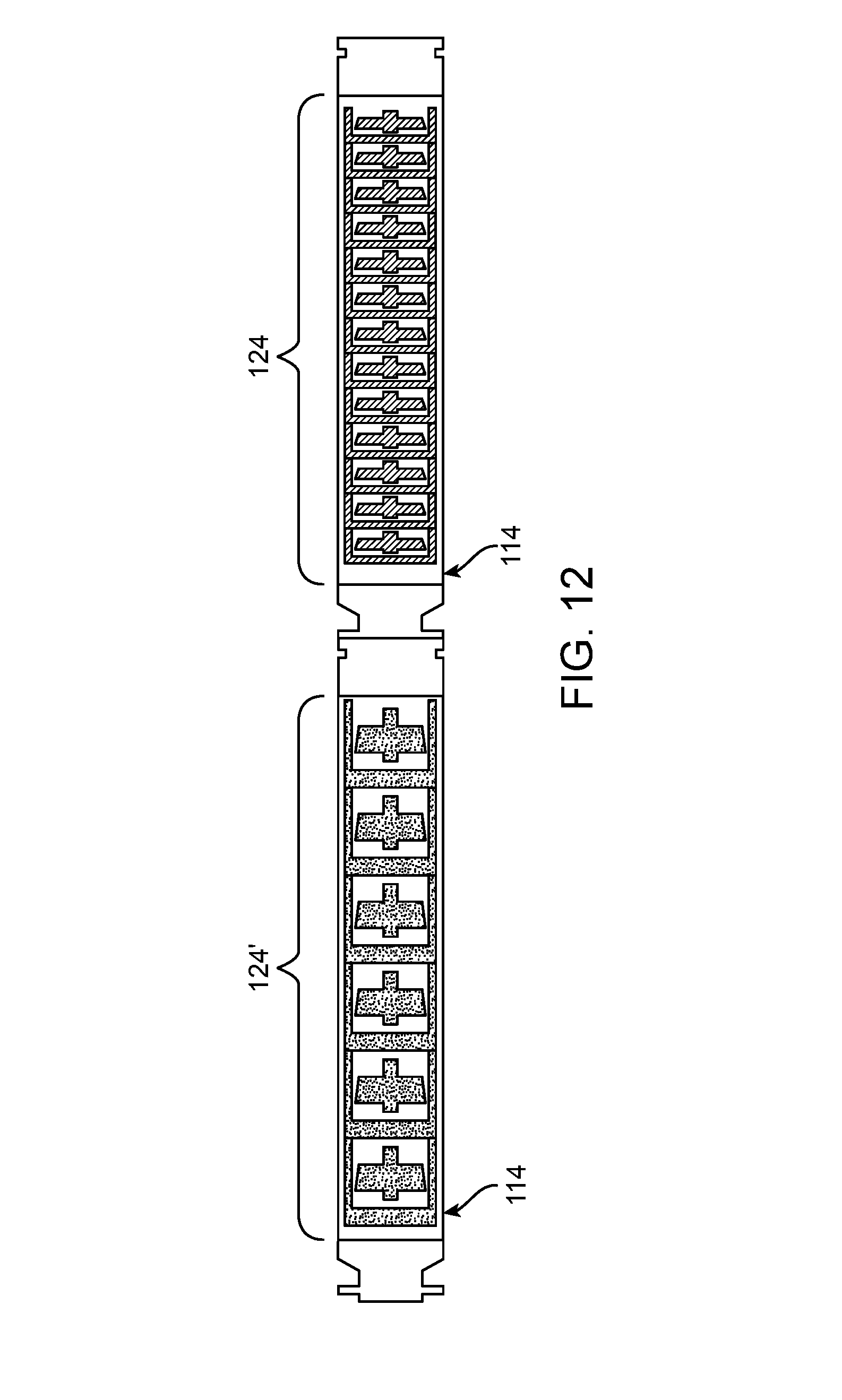
[0016] FIG. 12 is a diagram illustrating a third exemplary ESP according to the disclosure herein.
DETAILED DESCRIPTION
[0017] It will be appreciated that for simplicity and clarity of illustration, where appropriate, reference numerals have been repeated among the different figures to indicate corresponding or analogous elements. In addition, numerous specific details are set forth in order to provide a thorough understanding of the embodiments described herein. However, it will be understood by those of ordinary skill in the art that the embodiments described herein can be practiced without these specific details. In other instances, methods, procedures and components have not been described in detail so as not to obscure the related relevant feature being described. Also, the description is not to be considered as limiting the scope of the embodiments described herein. The drawings are not necessarily to scale and the proportions of certain parts have been exaggerated to better illustrate details and features of the present disclosure.
[0018] In the following description, reference to up or down is made for purposes of description with "up," "upper," "upward," or "uphole" meaning toward the surface of the wellbore and with "down," "lower," "downward," or "downhole" meaning toward the terminal end of the well, regardless of the wellbore orientation. Correspondingly, the transverse, axial, lateral, longitudinal, radial, etc., orientations shall mean orientations relative to the orientation of the wellbore or tool. Additionally, the illustrated embodiments are illustrated such that the orientation is such that the top of the page is toward the surface, and the lower side of the page is downhole. A "pump" as used herein can include Electric Submersible Pump (ESP). The term pump and ESP are used interchangeably within this disclosure.
[0019] Several definitions that apply throughout this disclosure will now be presented. The term "coupled" is defined as connected, whether directly or indirectly through intervening components, and is not necessarily limited to physical connections. The terms "inside" or "inner" indicate that at least a portion of a region is partially contained within a boundary formed by the object. The terms "comprising," "including" and "having" are used interchangeably in this disclosure. The terms "comprising," "including" and "having" mean to include, but not necessarily be limited to the things so described.
[0020] Disclosed herein is an electric submersible pump (ESP) having a variety of different stages and impellers to reduce gas lock within the pump. The ESP can be attached to a downhole tubing string and used for creating artificial pressure or lift in a wellbore. The pump can have a housing containing one or more standard flow stages and one or more anti-gas lock flow stages. The housing can have a head plate and a base portion at opposing ends, the head plate being at the end nearest the wellhead and the base portion at the end furthest from the wellhead. Each stage can include a diffuser and an impeller to aid in moving or displacing fluid and gas. The one or more stages can be stackable one upon the other, such that one diffuser sits substantially on top of another. The stack can be referred to as a diffuser stack. The impeller can be substantially received within the diffuser. The impeller can rotate around a longitudinal axis within the diffuser. During operation, the diffuser remains stationary relative to the housing. To disrupt gas bubble formation, a plurality of anti-gas lock flow stages can be placed near the base portion of the housing, or strategically spaced throughout the length of the housing.
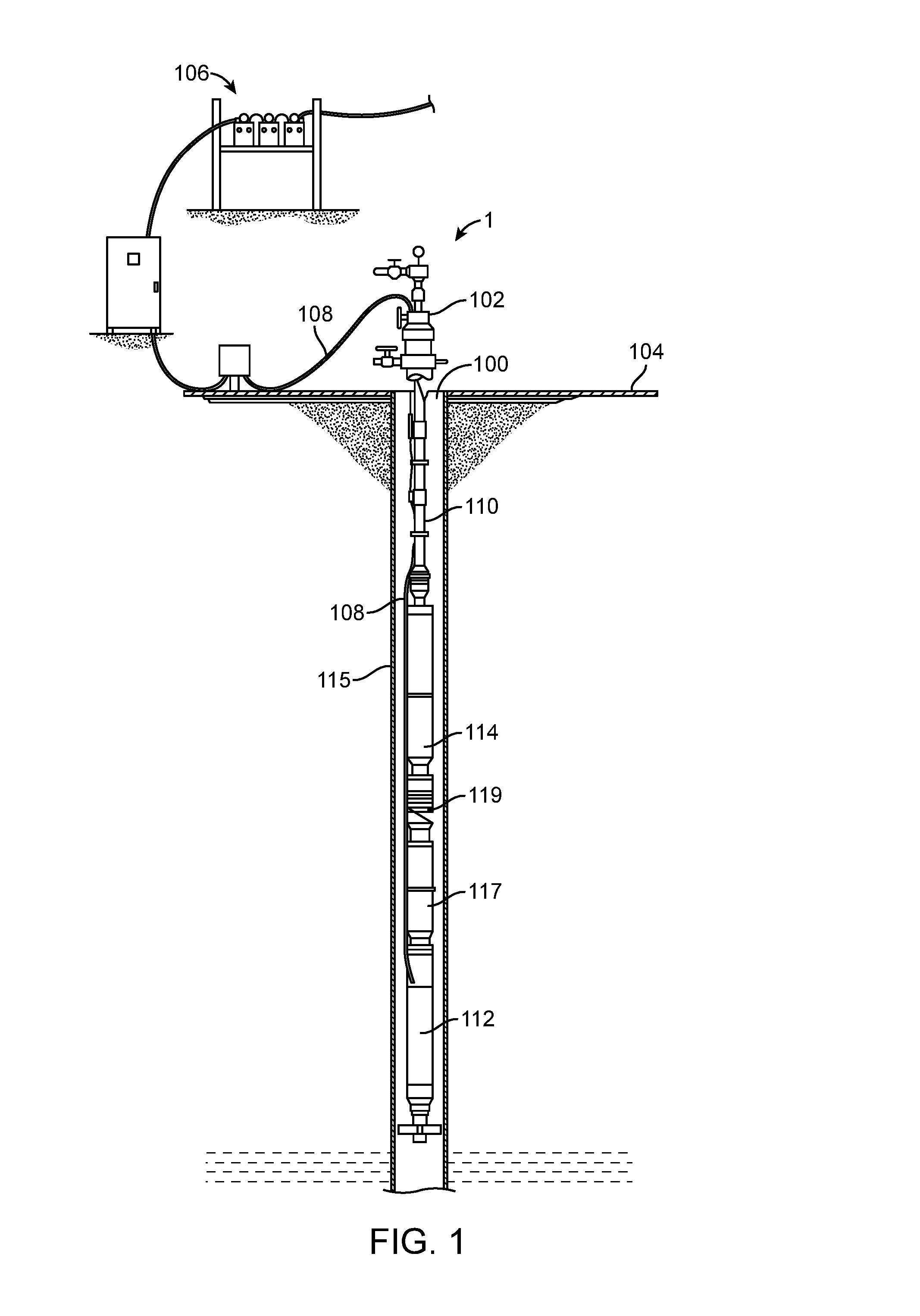
[0021] The ESP 114 can be employed in an exemplary wellbore pumping system 1 shown for example in FIG. 1. The system 1 includes a wellbore 100 having a wellhead 102 at the surface 104. The wellbore 100 extends and penetrates various earth strata including hydrocarbon containing formations. A casing 115 can be cemented along a length of the wellbore 100. A power source 106 can have an electrical cable 108, or multiple electrical cables, extending into the wellbore 100 and coupled with a motor 112. It should be noted that while FIG. 1 generally depicts a land-based operation, those skilled in the art will readily recognize that the principles described herein are equally applicable to subsea operations that employ floating or sea-based platforms and rigs, without departing from the scope of the disclosure. Also, even though FIG. 1 depicts a vertical wellbore, the present disclosure is equally well-suited for use in wellbores having other orientations, including horizontal wellbores, slanted wellbores, multilateral wellbores or the like.
[0022] Disposed within the wellbore 100 can be a tubing string 110 having an ESP 114 forming an electric submersible pump string. The ESP 114 may be driven by a motor 112. The tubing string 110 can also include a pump intake 119 for withdrawing fluid from the wellbore 100. The pump intake 119, or pump admission, can separate the fluid and gas from the withdrawn hydrocarbons and direct the fluid into the ESP 114. A protector 117 can be provided between the motor 112 and the pump intake 119 to prevent entrance of fluids into the motor 112 from the wellbore. The tubing string 110 can be a series of tubing sections, coiled tubing, or other conveyance for providing a passageway for fluids. The motor 112 can be electrically coupled with the power source 106 by the electrical cable 108. The motor 112 can be disposed below the ESP 114 within the wellbore 100. The ESP 114 can provide artificial pressure, or lift, within the wellbore 100 to increase the withdrawal of hydrocarbons, and/or other wellbore fluids. The ESP 114 can provide energy to the fluid flow from the well thereby increasing the flow rate within the wellbore 100 toward the wellhead 102
[0023] Illustrated in FIG. 2 is one example of an ESP 114. The ESP 114 can have a housing 116 having a head plate 118 and a base portion 120. The head plate 118 can be disposed at the upper portion of the housing 116 and the base portion 120 can be disposed at the lower portion of the housing 116. The housing 116 can further include at least one inlet 160 and at least one outlet 162. Each inlet 160 has an opening to allow fluids, such as hydrocarbons, to enter the ESP 114 and each outlet 162 also has an opening to allow fluids to exit after passing through the ESP 114. The housing 116 can receive a diffuser stack 122. Multiple diffuser stacks 122 can be provided in the housing 116. The diffuser stack 122 includes one or more stages 124.
[0024] Multiple stages 124 can be stacked one upon the other to increase the energy added to the flow within the wellbore 100. Any number of stages can be employed, depending on the requirements of the system 1. Longer wellbore holes may require a larger number of stages 124, and therefore longer diffuser stacks, due to the increased lift requirements as a result of the increased volume of the wellbore. For example, a 5,000 foot long hole may require as many as 50 stages 124 to provide sufficient lift. Longer diffuser stacks or ESP's can be provided, for example, a 10,000 foot long wellbore hole may require as many as 75 stages 124. Any number of stages can be employed, however, typically there can be anywhere from 10 to 100 stages, alternatively 25 to 75 stages.
[0025] Each stage 124 of the diffuser stack 122 can be made up of an individual diffuser 126 and an individual impeller 128 received within the diffuser 126. Typically each stage 124 in the diffuser stack 122 is substantially identical, having substantially identical diffusers 126 and impellers 128 at each stage. However, as described above, this can lead to gas lock within the pump. Thus, as described in further detail below, several modified stages 124' (as shown in FIGS. 9-12) can be included throughout the pump. The diffuser stack 122 having the one or more stages 124 can be configured to handle various fluids. For example, different types of impellers 128 and diffusers 126 can be employed depending on the fluids to be pumped, desired pressure or other requirements in the system. For example, the fluids to be pumped can be clear liquids, brine, saltwater, hydrocarbons, mud, abrasives or gas, or other wellbore fluids. Accordingly, the impellers and diffusers can be configured to accommodate the particular fluids and conditions of the wellbore. The arrangement of the diffuser stack 122 can depend on the wellbore 100 and the hydrocarbon mixture being withdrawn therefrom.
[0026] As illustrated in FIG. 2, the impeller 128 is provided to rotate within the diffuser 126 about an impeller hub 130. The impeller hub 130 can extend at least partially above the main body of the impeller 128 to be received by an adjacent impeller 128 in the stage above. The diffuser 126 can also have an aperture through which the impeller hub 130 extends. The impeller hub 130 can extend partially above and/or partially below the main body of the impeller 128 and couple with impeller hubs 130 above and/or below in a stacking fashion. For example, the portion of the impeller hub 130 extending partially above the impeller 128 couples with the impeller hub 130 of the stage 124 stacked directly above, whereas the portion of the impeller hub 130 extending partially below the impeller 128 couples with the impeller hub 130 of the stage 124 stacked directly below. The impeller hub 130 of the stage 124 at the top of the diffuser stack 122 can be received by the head plate 118. The impeller hub 130 of the stage 124 at the bottom of the diffuser stack 122 can be received at the base portion 120 and coupled with the motor 112 (shown in FIG. 1). Accordingly, the impeller hubs 130 together can form a shaft extending throughout the diffuser stack 122.
[0027] The diffuser stack 122 can be compressed within the housing 116 to prevent recirculation of fluid between the one or more stages 124. The diffuser stack 122 can be compressed between the head plate 118 and the base portion 120. A compression bearing 132 can be disposed above the head plate 118 and can apply mechanical compression force on the diffuser stack 122. The base portion 120 can have substantial strength to resist the compressive force therefore causing the diffuser stack 122 to compress. For example, the compression bearing 132 can be a spider wheel bearing configured to engage threads on the upper portion of the impeller hub 130 and compress the head plate 118 into the diffuser 126 of the uppermost stage 124 in the diffuser stack 122. The compression bearing 132 can compress the diffuser stack 122 a predetermined distance, such as from 1/2,500.sup.th of an inch to 1/500.sup.th of an inch, or alternatively from 1/2,000.sup.th of an inch to 1/1,000.sup.th of an inch.
[0028] Illustrated in FIG. 3 is an example of a two-stage 124 diffuser stack 122. One diffuser 126 of one stage 124 can be stacked on top of another diffuser 126 of the adjacent stage 124'. The diffuser 126 can have a side wall 134 forming a contained receiving space 136. The impeller 128' can be substantially received within the diffuser 126 receiving space. The upper portion of the impeller hub 130 can extend beyond the upper surface of side wall 134 of the diffuser 126. The upper portion of impeller hub 130 can have at least one groove 139 formed on the inner surface. The at least one groove 139 can couple with the impeller hub 130 with the stage 124 directly above in the diffuser stack 122. As can be appreciated in FIG. 3, the diffusers 126 can be stacked and the side wall 134 of each diffuser 126 can form a substantially flush coupling with the adjacent stage 124.
[0029] Illustrated in FIG. 4 is an example embodiment of a standard impeller 128 for use in a standard flow stage. The impeller 128 can be received in the diffuser receiving space. During operation, the impeller 128 can float within the diffuser such that the impeller 128 does not contact the diffuser side wall 134 (shown in FIG. 3). The impeller 128 can have a top shroud 150, a bottom shroud 152, and a plurality of vanes 148 to impart energy in the fluid as the impeller 128 rotates within the diffuser 126. The top shroud 150 and the bottom shroud 152 can have diameters that are equal to one another. The plurality of vanes 148 can be angled to impart energy in a direction corresponding to the plurality of inlets within the diffuser 126. The angle can be, for example, from about 15 degrees to about 40 degrees; in the alternative the angle can be from about 20 degrees to about 30 degrees. The standard flow stages, or radial flow stages, are designed to target flow ranges below 1000 barrels per day (bbl/d). Such stages can generate more head per linear foot of pump than other stages; however they are sensitive to gas ingestion due to the tight radial flow path. As a result, gas can become trapped within the stage's vanes and block fluid movement throughout the length of the pump, for example, gas lock. In the illustrated embodiment, the impeller hub 130 extends beyond the upper surface of the impeller 128. The impeller hub 130 can extend to various lengths, for example, beyond the lower surface of the impeller 128. The impeller hub 130 can be made to extend a larger amount above or below, or an equal amount above and below the main body of the impeller 128. The impeller hub 130 at each impeller can matingly engage with impeller hubs of adjacent impellers to form a shaft within the ESP.
[0030] To prevent gas lock throughout the ESP, modified stages, or anti-gas lock flow stages 124' (as shown in FIGS. 9-12), can be used to disrupt gas bubble formation. The anti-gas lock flow stages 124' can include modified impellers 128', as shown in FIGS. 5-8. In order to disrupt the gas bubble formation, the modified impeller 128' includes a fluid leakage that is not present in the standard impeller design which decreases the incidence of trapped gas. For example, FIG. 5 illustrates a first modified impeller 128', having a portion of the top shroud removed. The modified impeller 128' comprises a plurality of vanes 156, each of the vanes having a curvature less than the curvature of vanes 148 present in a standard impeller 128 (as shown in FIG. 4). The flatter curve of the vanes 156 in the modified impeller 128' aids in the disruption of gas-bubble formation by increasing the force on the fluid at the trailing edge of the vane per rotation. While FIG. 5 generally depicts a modified impeller having a portion of the top shroud removed, the impeller could also be modified by having a portion of the bottom shroud removed.
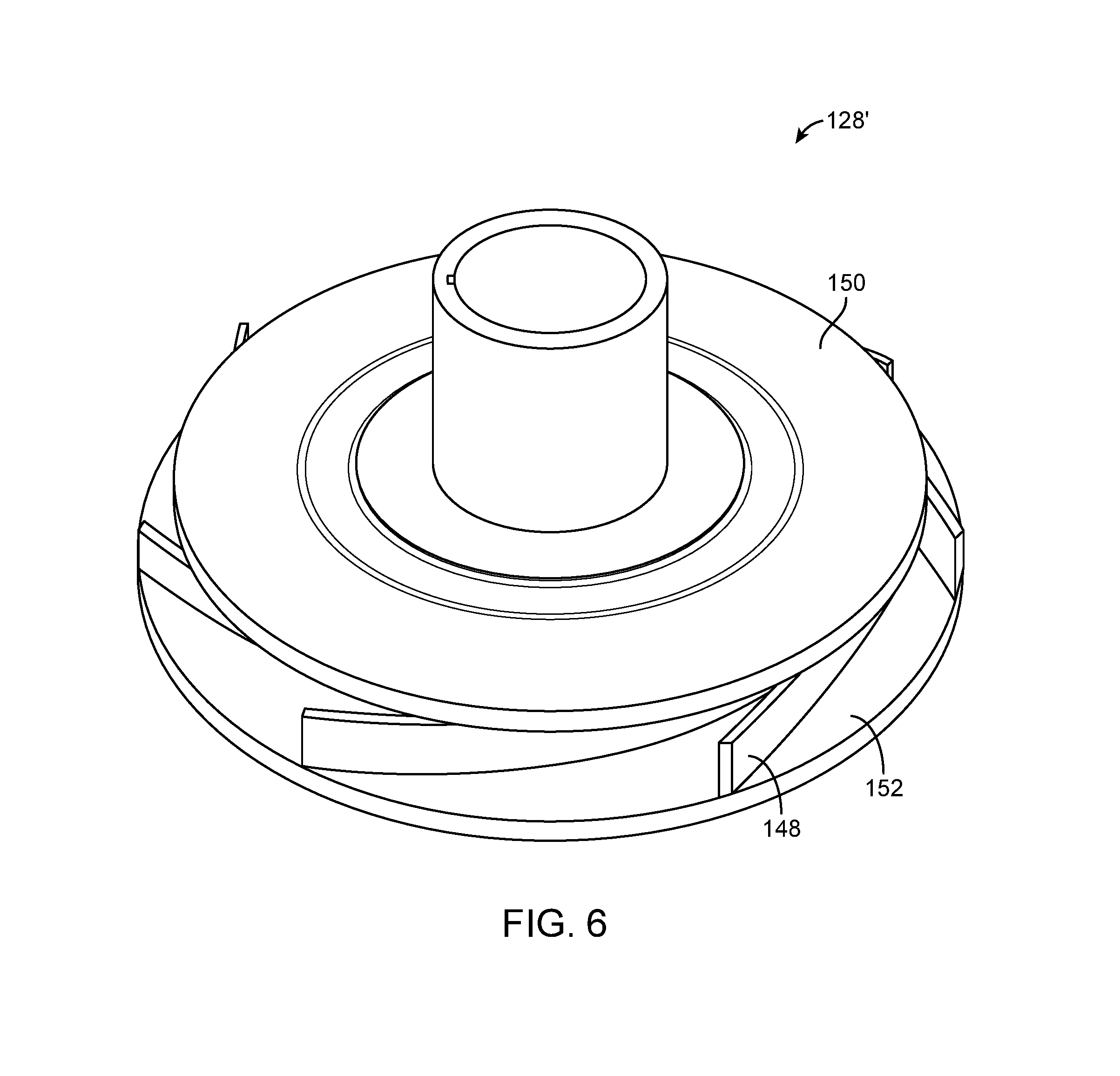
[0031] In the alternative, a modified impeller 128' can be created by providing an exit path for any gas trapped within the anti-gas lock flow stage 124'. For example, FIG. 6 illustrates a second type of modified impeller 128' wherein the top shroud 150 has a diameter less than the diameter of the bottom shroud 152. By opening the area immediately above the tip of the vanes, a fluid leakage point is provided, allowing for trapped gas to escape, and increasing fluid flow and turbulence within the stage. A third type of modified impeller 128' is shown in FIG. 7. The modified impeller 128' can include a plurality of apertures 160, providing the fluid leakage point. The apertures 160 can be present in one of the top shroud 150, the bottom shroud 152, the vanes 148, or any combination thereof. While the apertures 160 provide the fluid leakage point necessary to reduce gas build-up, they can also be a source of inefficiency throughout the pump by reducing the energy stored in the fluid as it rises through the impeller.
[0032] In an alternative embodiment, the modified impeller 128' as disclosed herein can have a combination of different fluid leakage points. For example, FIG. 8 illustrates a fourth modified impeller 128' having a top shroud 150 with a smaller diameter than the bottom shroud 152 as well as plurality of apertures 160.
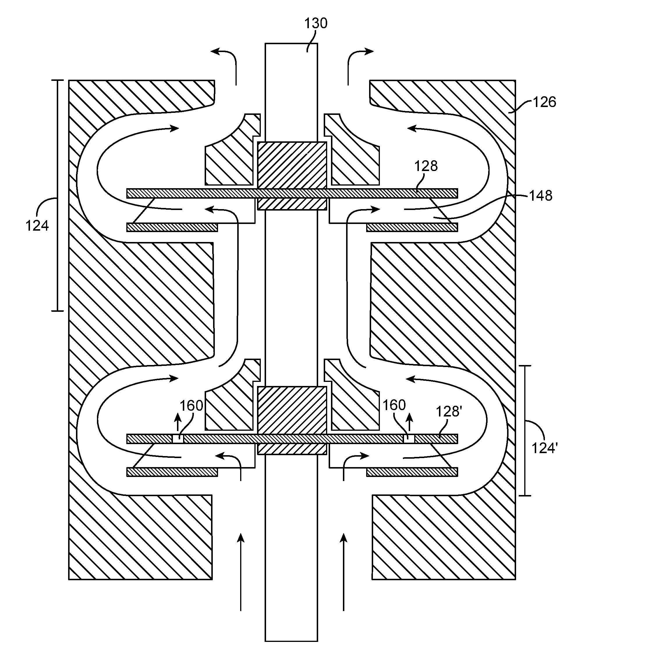
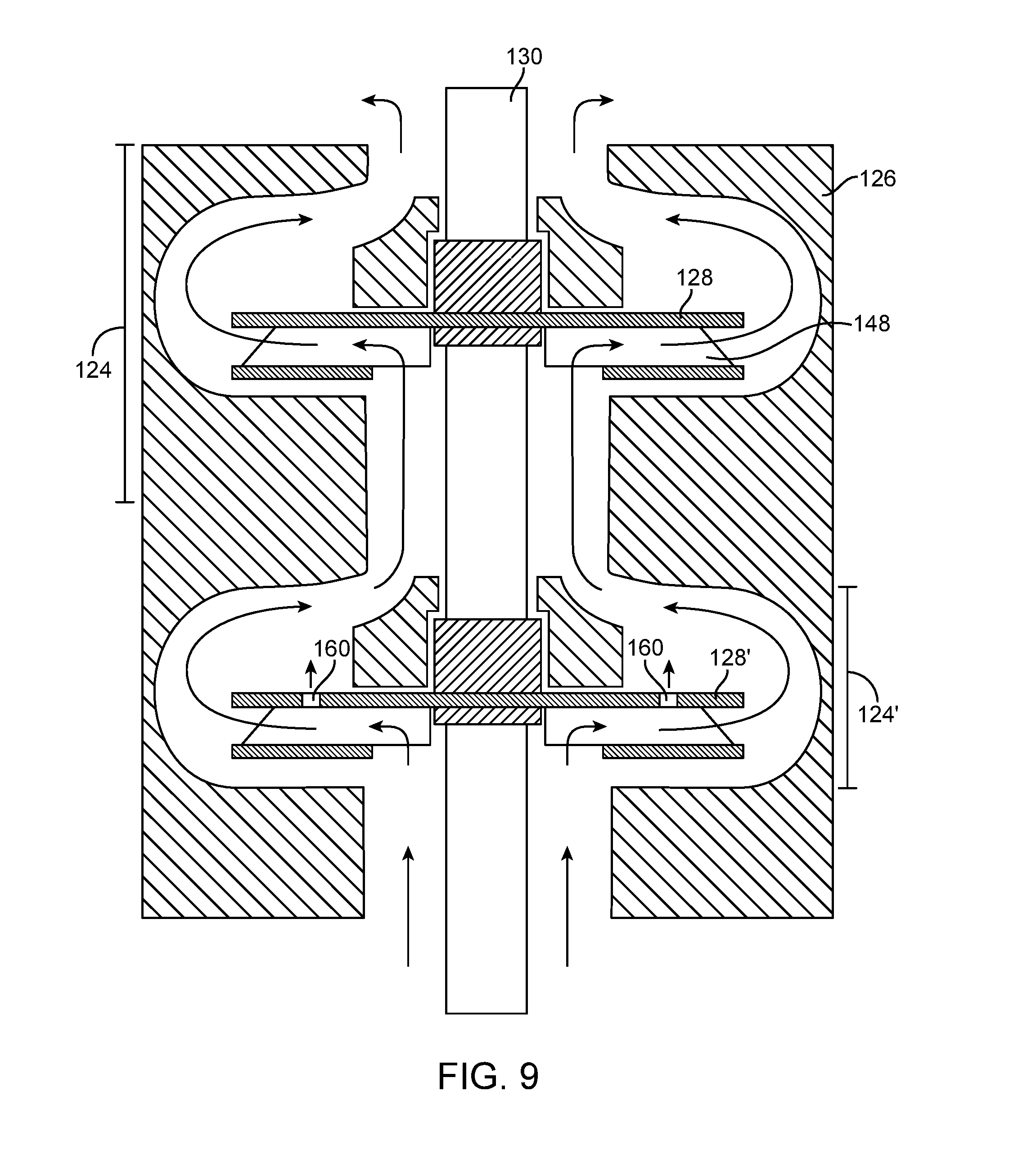
[0033] An ESP having only anti-gas lock flow stages 124' would be significantly less efficient than ESPs having only standard flow stages 124 due to the significant decrease in energy stored in the fluid. However, by combining both anti-gas lock flow stages 124' and standard flow stages 124, a more efficient pump can be produced. As the gas and liquid move upward through the pump, the gas is compressed back into the fluid. It is proposed herein, without being bound to any particular theory, that most of the compression occurs in the initial stages of the pump. Thus, by placing one or more anti-gas lock flow stages nearest the base plate of the housing, the formation of gas bubbles can be disrupted, thereby significantly reducing gas buildup throughout the pump. It is believed, as long as the initial stage(s) of the ESP are able to continuously operate and move fluid, the stages above will also maintain continuous motion; thus preventing gas lock throughout the pump as a whole. For example, FIG. 9 is a diagrammatic illustration of a standard flow stage 124 on top of an anti-gas lock flow stage 124' for use in an ESP 114. The stages 124, 124' can impart energy into fluid flowing through the ESP 114. The modified impeller 128' can induce a pressure differential within the diffuser 126 causing fluid to move from the bottom of the diffuser 126 to the receiving space and then into the standard flow stage 124 above. As can be appreciated in FIG. 9, as the modified impeller 128' rotates within the diffuser 126 fluid (or hydrocarbons) moves from the anti-gas lock flow stage 124' to the standard flow stage 124 above, adding energy to the fluid flow. While the illustrated embodiment has two stages, it would be obvious to those in the art that any number of standard flow stages 124 and anti-gas lock flow stages 124' can be employed, depending on the environment and desired flow.
[0034] The ESP 114 may include a plurality of anti-gas lock flow stages 124' disposed near the base plate of the housing, as shown in FIG. 10. For example, the first 5 stages, alternatively, the first 10 stages, alternatively, the first 15 stages, alternatively the first 20 stages, or alternatively, the first 5-20 stages, within the ESP can be anti-gas lock flow stages 124'. While the initial stages may be anti-gas lock flow stages 124', the stages disposed on top of the initial set of anti-gas lock flow stages 124' may be standard flow stages 124. Alternatively, a majority of the initial 5 stages, or initial 10 stages, or initial 15 stages, or initial 20 stages may be anti-gas lock flow stages 124' and the remainder standard flow stages 124. Alternatively, the first 5%, or 10%, or 15%, or 20%, or 25% stages, out of the total number of stages in the electric submersible pump, or a majority of such stages, disposed near the base plate of the housing may be anti-lock stages 124' and the remainder standard flow stages 124.
[0035] The stages may be mixed throughout, having a plurality of anti-gas lock flow stages 124' mixed amongst a plurality of standard flow stages 124. For example, at least 5% of the stages, or at least 10% of the stages, or at least 15% of the stages, or at least 20% of the stages, or at least 25% of the stages, out of the total number of stages may be anti-gas lock flow stages 124' and the remainder standard standard flow stages 124. The anti-gas lock flow stages 124' may be dispersed at various points throughout the ESP, as shown in FIG. 11. For example, the initial set of stages can be anti-gas lock flow stages 124' and additional anti-gas lock flow stages 124' can be dispersed throughout a plurality of standard flow stages 124 at predetermined locations throughout the ESP. Different arrangements can be created, depending on the intended use for the pump, as well as the targeted flow range. Additionally, the modified impellers 128' used in the anti-gas lock flow stages 124' do not have to be the same throughout the ESP, different modified impellers 128' can be used at different points throughout the pump in order to optimize production. For example, fluid mixtures with high gas-to-liquid ratios and a low water concentration (<10%) can be produced better using an anti-gas lock flow stage 124' designed for marginally grater total volumetric flow.
[0036] Alternatively, the ESP can include two or more housings 114 strung together, as shown in FIG. 12. For example, the downhole housing 114 can include a plurality of anti-gas lock flow stages 124' and the uphole housing 114 can include a plurality of standard flow stages 124. Thus, any gas that enters the pump is compressed back into the liquid prior to reaching the standard flow stages 124 and preventing gas lock throughout the pump. The uphole housings may also include one or more anti-gas lock flow stages 124' at strategic positions in order to maintain the desired flow rate. Although FIG. 12 only illustrates two housing, it would be apparent to those of skill in the art that any number of housings could be used.
[0037] While the above embodiments have been described in detail in the foregoing description, the same is to be considered as illustrative and not restrictive in character, it being understood that only some embodiments have been shown and described and that all changes and modifications that come within the spirit of the embodiments are desired to be protected. Specifically, it should be known that ESP pumps are typically assembled on site, allowing for the arrangement to be continuously changed and updated based on the specific needs of the user. Thus, it would be apparent to one of skill in the art that any arrangement of standard flow stages 124 and anti-gas lock flow stages 124' could be used.
[0038] Furthermore, the above described system can be used in combination with a variable speed drive (VSD) in order to further enhance the system performance. For example, as gas is ingested into a pump downhole, the torque load on the pump is reduced; the loss in load will typically cause an increase in drive speed throughout the pump. This increase in speed generates more flow throughout the pump, which will increase the torque on the driving motor and consuming more current. When a pump encounters an overwhelming amount of gas within the system the load loss can be extreme resulting in a total system shutdown. However, a VSD can run a series of gas purging by slowing the speed of the pump in response to significant load loss, allowing the fluid column in the tubing to reduce velocity and expelling the trapped gas out of the pump's discharge. The VSD can also cause an intentional disruption in the fluid flow throughout the pump massaging the trapped gas out of the pump. However, use of a VSD alone is not always effective, use in combination with the anti-gas lock flow stages described above increase efficiency of the VSD by providing stages that are able to support the intentional disruption.
[0039] Numerous examples are provided herein to enhance understanding of the present disclosure. A specific set of statements are provided as follows.
[0040] Statement 1: An electric submersible pump comprising a housing having a longitudinal axis extending therethrough; and a plurality of stages disposed within the housing each stage having an impeller and a diffuser, the plurality of stages stackable one upon the other along the longitudinal axis of the housing, wherein one or more of the plurality of stages is a standard flow stage, wherein one or more of the plurality of stages is an anti-gas lock flow stage, and wherein the anti-gas lock flow stages are modified relative the standard flow stages to have decreased incidence of trapped gas.
[0041] Statement 2: An electric submersible pump in accordance with Statement 1, wherein the anti-gas lock flow stages have a fluid leakage point absent in the standard flow stages thereby decreasing the incidence of trapped gas.
[0042] Statement 3: An electric submersible pump in accordance with Statement 1 or Statement 2, wherein the impeller of the one or more anti-gas lock flow stages comprises a top shroud, a bottom shroud, and one or more vanes.
[0043] Statement 4: An electric submersible pump in accordance with Statements 1-3, wherein the fluid leakage point comprises apertures formed in one or more of the top shroud, the bottom shroud, and the one or more vanes.
[0044] Statement 5: An electric submersible pump in accordance with Statements 1-4, wherein the diameter of the top shroud is less than the diameter of the bottom shroud, thereby forming the fluid leakage point.
[0045] Statement 6: An electric submersible pump in accordance with Statements 1-5, wherein the diameter of the bottom shroud is less than the diameter of the top shroud, thereby forming the fluid leakage point.
[0046] Statement 7: An electric submersible pump in accordance with Statements 1-6, wherein the housing further comprises a head plate and a base portion.
[0047] Statement 8: An electric submersible pump in accordance with Statements 1-7wherein an initial set of the plurality of stages nearest the base portion are anti-gas lock flow stages.
[0048] Statement 9: An electric submersible pump in accordance with Statements 1-8, wherein the initial set comprises at least 5 stages.
[0049] Statement 10: An electric submersible pump in accordance with Statements 1-9, wherein the initial set comprises at least 10 stages.
[0050] Statement 11: An electric submersible pump in accordance with Statements 1-10, wherein a plurality of standard flow stages are stacked on top of the initial set of anti-gas lock flow stages, relative the base portion.
[0051] Statement 12: An electric submersible pump in accordance with Statements 1-11, wherein a majority of an initial set of the plurality of stages nearest the base portion are anti-gas lock flow stages.
[0052] Statement 13: An electric submersible pump in accordance with Statements 1-12, further comprising a plurality of standard flow stages and a plurality of anti-gas lock flow stages.
[0053] Statement 14: An electric submersible pump in accordance with Statements 1-13, wherein the plurality of anti-gas lock flow stages are dispersed throughout the plurality of standard flow stages.
[0054] Statement 15: An electric submersible pump in accordance with Statements 1-14, wherein the impeller of the one or more standard flow stages comprises a top shroud, a bottom shroud, and one or more vanes.
[0055] Statement 16: An electric submersible pump in accordance with Statements 1-15, wherein the curvature of the one or more vanes of the anti-gas lock flow stage is less than the curvature of the one or more vanes of the standard flow stage.
[0056] Statement 17: A system comprising a tubing string; and an electric submersible pump string coupled with the tubing string, wherein the electric submersible pump string comprises at least one housing having a longitudinal axis extending therethrough, and a plurality of stages disposed within the housing each stage having an impeller and a diffuser, the plurality of stages stackable one upon the other along the longitudinal axis of the housing, wherein one or more of the plurality of stages is a standard flow stage, wherein one or more of the plurality of stages is an anti-gas lock flow stage, and wherein the anti-gas lock flow stages are modified relative the standard flow stages to have decreased incidence of trapped gas.
[0057] Statement 18: A system in accordance with Statement 17, wherein the anti-gas lock flow stages have a fluid leakage point absent in the standard flow stages thereby decreasing the incidence of trapped gas.
[0058] Statement 19: A system in accordance with Statement 17 or Statement 18, wherein the impeller of the one or more anti-gas lock flow stages comprises a top shroud, a bottom shroud, and one or more vanes.
[0059] Statement 20: A system in accordance with Statements 17-19, wherein the fluid leakage point comprises apertures formed in one or more of the top shroud, the bottom shroud, and the one or more vanes.
[0060] Statement 21: A system in accordance with Statements 17-20, wherein the diameter of the top shroud is less than the diameter of the bottom shroud, thereby forming the fluid leakage point.
[0061] Statement 22: A system in accordance with Statements 17-21, wherein the diameter of the bottom shroud is less than the diameter of the top shroud, thereby forming the fluid leakage point.
[0062] Statement 23: A system in accordance with Statements 17-22, wherein the at least one housing further comprises a head plate and a base portion.
[0063] Statement 24: A system in accordance with Statements 17-23, wherein an initial set of the plurality of stages nearest the base portion are anti-gas lock flow stages.
[0064] Statement 25: A system in accordance with Statements 17-24, wherein the initial set comprises at least 5 stages.
[0065] Statement 26: A system in accordance with Statements 17-25, wherein the initial set comprises at least 10 stages.
[0066] Statement 27: A system in accordance with Statements 17-26, wherein a plurality of standard flow stages are stacked on top of the initial set of anti-gas lock flow stages, relative the base portion.
[0067] Statement 28: A system in accordance with Statements 17-27, wherein a majority of an initial set of the plurality of stages nearest the base portion are anti-gas lock flow stages.
[0068] Statement 29: A system in accordance with Statements 17-28, further comprising a plurality of standard flow stages and a plurality of anti-gas lock flow stages.
[0069] Statement 30: A system in accordance with Statements 17-29, wherein the plurality of anti-gas lock flow stages are dispersed throughout the plurality of standard flow stages.
[0070] Statement 31: A system in accordance with Statements 17-30, wherein the electric submersible pump comprises a first housing and a second housing, wherein the second housing is disposed uphole of the first housing.
[0071] Statement 32: A system in accordance with Statements 17-31, wherein the first housing comprises a plurality of anti-gas lock flow stages, and the second housing comprises a plurality of standard flow stages.
[0072] Statement 33: A system in accordance with Statements 17-32, wherein the impeller of the one or more standard flow stages comprises a top shroud, a bottom shroud, and one or more vanes.
[0073] Statement 34: A system in accordance with Statements 17-33, wherein the curvature of the one or more vanes of the anti-gas lock flow stage is less than the curvature of the one or more vanes of the standard flow stage.
[0074] Statement 35: A method for preventing gas lock comprising providing an electronic submersible pump comprising a housing having a longitudinal axis extending therethrough, and a plurality of stages disposed within the housing each stage having an impeller and a diffuser, the plurality of stages stackable one upon the other along the longitudinal axis of the housing, wherein one or more of the plurality of stages is a standard flow stage, wherein one or more of the plurality of stages is an anti-gas lock flow stage, and wherein the anti-gas lock flow stages are modified relative the standard flow stages to have decreased incidence of trapped gas; disposing the electronic submersible pump into a wellbore via a tubing string; and generating a fluid flow through the housing by rotation of the impeller within the one or more standard flow stages and the one or more anti-gas lock flow stages.
[0075] Statement 36: A method in accordance with Statement 35, wherein the anti-gas lock flow stages have a fluid leakage point absent in the standard flow stages thereby decreasing the incidence of trapped gas.
[0076] Statement 37: A method in accordance with Statement 35 or Statement 36, wherein the impeller of the one or more anti-gas lock flow stages comprises a top shroud, a bottom shroud, and one or more vanes.
[0077] Statement 38: A method in accordance with Statements 35-37, wherein the fluid leakage point comprises apertures formed in one or more of the top shroud, the bottom shroud, and the one or more vanes.
[0078] Statement 39: A method in accordance with Statements 35-38, wherein the diameter of the top shroud is less than the diameter of the bottom shroud, thereby forming the fluid leakage point.
[0079] Statement 40: A method in accordance with Statements 35-39, wherein the diameter of the bottom shroud is less than the diameter of the top shroud, thereby forming the fluid leakage point.
[0080] Statement 41: A method in accordance with Statements 35-40, wherein the housing further comprises a head plate and a base portion.
[0081] Statement 42: A method in accordance with Statements 35-41, further comprising disposing an initial set of anti-gas lock flow stages nearest the base portion of the housing.
[0082] Statement 43: A method in accordance with Statements 35-42, wherein the initial set comprises at least 5 stages.
[0083] Statement 44: A method in accordance with Statements 35-43, wherein the initial set comprises at least 10 stages.
[0084] Statement 45: A method in accordance with Statements 35-44, further comprising disposing a plurality of standard flow stages on top of the initial set of anti-gas lock flow stages, relative the base portion.
[0085] Statement 46: A method in accordance with Statements 35-45, wherein a majority of an initial set of the plurality of stages nearest the base portion are anti-gas lock flow stages.
[0086] Statement 47: A method in accordance with Statements 35-46, wherein the electric submersible pump further comprises a plurality of standard flow stages and a plurality of anti-gas lock flow stages.
[0087] Statement 48: A method in accordance with Statements 35-47, further comprising dispersing the plurality of anti-gas lock flow stages throughout the plurality of standard flow stages.
[0088] Statement 49: A method in accordance with Statements 35-48, wherein the impeller of the one or more standard flow stages comprises a top shroud, a bottom shroud, and one or more vanes.
[0089] Statement 50: A method in accordance with Statements 35-49, wherein the curvature of the one or more vanes of the anti-gas lock flow stage is less than the curvature of the one or more vanes of the standard flow stage.
[0090] The embodiments shown and described above are only examples. Even though numerous characteristics and advantages of the present technology have been set forth in the foregoing description, together with details of the structure and function of the present disclosure, the disclosure is illustrative only, and changes may be made in the detail, especially in matters of shape, size and arrangement of the parts within the principles of the present disclosure to the full extent indicated by the broad general meaning of the terms used in the attached claims. It will therefore be appreciated that the embodiments described above may be modified within the scope of the appended claims.
* * * * *
D00000
D00001
D00002
D00003
D00004
D00005
D00006
D00007
D00008
D00009
XML
uspto.report is an independent third-party trademark research tool that is not affiliated, endorsed, or sponsored by the United States Patent and Trademark Office (USPTO) or any other governmental organization. The information provided by uspto.report is based on publicly available data at the time of writing and is intended for informational purposes only.
While we strive to provide accurate and up-to-date information, we do not guarantee the accuracy, completeness, reliability, or suitability of the information displayed on this site. The use of this site is at your own risk. Any reliance you place on such information is therefore strictly at your own risk.
All official trademark data, including owner information, should be verified by visiting the official USPTO website at www.uspto.gov. This site is not intended to replace professional legal advice and should not be used as a substitute for consulting with a legal professional who is knowledgeable about trademark law.