Waste Heat Recovery System
Scholz; Frank ; et al.
U.S. patent application number 16/087715 was filed with the patent office on 2019-02-14 for waste heat recovery system. The applicant listed for this patent is Robert Bosch GmbH. Invention is credited to Frank Scholz, Peter Schwaderer, Benjamin Schweizer.
| Application Number | 20190048749 16/087715 |
| Document ID | / |
| Family ID | 61656381 |
| Filed Date | 2019-02-14 |

| United States Patent Application | 20190048749 |
| Kind Code | A1 |
| Scholz; Frank ; et al. | February 14, 2019 |
WASTE HEAT RECOVERY SYSTEM
Abstract
The invention relates to a waste heat recovery system (1) comprising a working fluid circuit (18), having a heat exchanger which is connected in an exhaust gas line (4) of an internal combustion engine (2). The heat exchanger is part of the working fluid circuit (18) together with an expansion machine (20) which has at least one working fluid bypass (21) that is controlled by a valve. According to the invention, a waste heat recovery system (1) is provided with improved functionality. This is achieved in that the valve is a directional valve which connects a fluid inlet (36) to an expansion machine fluid outlet (37) and/or a bypass fluid outlet (38), in particular a 3/2-way valve (22), and the connection of the fluid inlet (36) to the expansion machine fluid outlet (37) is leakage-free relative to the bypass fluid outlet (38), whereas the connection of the fluid inlet (36) to the bypass fluid outlet (38) exhibits leakages with respect to the expansion machine fluid outlet (37).
| Inventors: | Scholz; Frank; (Stuttgart-Feuerbach, DE) ; Schweizer; Benjamin; (Horb, DE) ; Schwaderer; Peter; (Wildberg, DE) | ||||||||||
| Applicant: |
|
||||||||||
|---|---|---|---|---|---|---|---|---|---|---|---|
| Family ID: | 61656381 | ||||||||||
| Appl. No.: | 16/087715 | ||||||||||
| Filed: | November 17, 2016 | ||||||||||
| PCT Filed: | November 17, 2016 | ||||||||||
| PCT NO: | PCT/EP2016/077992 | ||||||||||
| 371 Date: | September 24, 2018 |
| Current U.S. Class: | 1/1 |
| Current CPC Class: | F05D 2220/40 20130101; Y02T 10/16 20130101; Y02T 10/12 20130101; F01N 5/02 20130101; F16K 3/267 20130101; F01N 2410/00 20130101; F01K 23/065 20130101; F02G 5/02 20130101; F16K 31/061 20130101; F16K 31/0624 20130101 |
| International Class: | F01K 23/06 20060101 F01K023/06 |
Foreign Application Data
| Date | Code | Application Number |
|---|---|---|
| Mar 24, 2016 | DE | 10 2016 205 041.9 |
Claims
1. A waste-heat recovery system (1) with a working fluid circuit (18) having a heat exchanger connected into an exhaust-gas line (4) of the internal combustion engine (2), wherein the heat exchanger is part of the working fluid circuit (18) with at least one expansion machine (20) which has a working fluid bypass (21) controlled by a valve, wherein the valve is a directional valve (22) which connects a fluid inlet (36) to an expansion machine fluid outlet (37) and/or to a bypass fluid outlet (38), and wherein a connection made between the fluid inlet (36) and the expansion machine fluid outlet (37) exhibits no leakage to the bypass fluid outlet (38).
2. The waste-heat recovery system (1) as claimed in claim 1, characterized in that a connection made between fluid inlet (36) and the bypass fluid outlet (38) exhibits leakage, with a leakage quantity (46a, 46b), to the expansion machine fluid outlet (37).
3. The waste-heat recovery system (1) as claimed in claim 2, characterized in that the leakage quantity (46a, 46b) is less than 10% of the maximum volume flow of the working fluid.
4. The waste-heat recovery system (1) as claimed in claim 2, characterized in that the directional valve (22) has a slide (31) with two opposite switching positions that can be assumed by the slide (31).
5. The waste-heat recovery system (1) as claimed in claim 2, characterized in that the directional valve (22) has a slide housing (30) and a slide (31) which is displaceable in said slide housing axially counter to the force of a spring (32), which slide has a permanent flow connection to the fluid inlet (36) and can be adjusted in each case into a flow connection with the bypass fluid outlet (38) and with the expansion machine fluid outlet (37).
6. The waste-heat recovery system (1) as claimed in claim 2, characterized in that the directional valve (22) has a bypass fluid outlet seat (40) configured to have an end-side slide seat (41) of the slide (31) engaged therein with sealing action.
7. The waste-heat recovery system (1) as claimed in claim 2, characterized in that the slide housing (30) has an expansion machine fluid outlet seat (43) configured to have a slide edge (44) of the slide (31) engaged therein with sealing action.
8. The waste-heat recovery system (1) as claimed in claim 6, characterized in that the slide seat (41) is arranged on a slide base wall of the slide (31) of piston-like form, and in that the slide base wall has passage openings (45) for an unhindered throughflow of the working fluid.
9. The waste-heat recovery system (1) as claimed in claim 4, characterized in that the slide (31) interacts with an actuator (33).
10. The waste-heat recovery system (1) as claimed in claim 2, characterized in that the leakage quantity (46a, 46b) is less than 1% of the maximum volume flow of the working fluid,
Description
BACKGROUND OF THE INVENTION
[0001] The invention relates to a waste-heat recovery system with a working fluid circuit having a heat exchanger connected into an exhaust-gas line of the internal combustion engine, wherein the heat exchanger is part of the working fluid circuit with at least one expansion machine which has a bypass controlled by a valve.
[0002] A waste-heat recovery system of said type is known from DE 10 2013 021 251 A1. Said waste-heat recovery system has a working fluid circuit which has the conventional components. These are, substantially, an evaporator connected into an exhaust-gas line of an internal combustion engine, and expansion machine with the bypass control by a valve, a condenser, and a working fluid pump. By means of the bypass control by the valve, the expansion machine can be switched into a torque-free state. Here, the bypass and the valve are arranged within or integrated into the expansion machine.
SUMMARY OF THE INVENTION
[0003] The invention is based on the object of providing a waste-heat recovery system which is improved with regard to its function.
[0004] Said object is achieved in that the valve is a directional valve, in particular 3/2 directional valve, which connects a fluid inlet to an expansion machine fluid outlet and/or to a bypass fluid outlet, and in that a connection made between fluid inlet and expansion machine fluid outlet exhibits no leakage to the bypass fluid outlet. Said 3/2 directional valve can conduct the working fluid flowing and the working fluid circuit either via the expansion machine or, pass the expansion machine, directly to a condenser provided in the working fluid circuit downstream of the expansion machine. It is a first object of said 3/2 directional valve, for example in the case of a mechanical connection of the expansion machine to a crankshaft of the internal combustion engine, and in the presence of a torque demand of "zero", to conduct the working fluid directly to the condenser, such that the expansion machine is not driven by the working fluid and therefore outputs no torque to the crankshaft. It is a second object of the 3/2 directional valve to protect the expansion machine if the working fluid is in a wet steam range. During expander operation, in which the expansion machine is flowed through in the intended manner by the working fluid, leakage in the direction of the bypass, which would constitute an impairment of the efficiency of the expansion machine, is prevented according to the invention. By means of this embodiment, the function of the waste-heat recovery system is improved.
[0005] In a refinement of the invention, a connection made between fluid inlet and bypass fluid outlet exhibits leakage, with a leakage quantity, to the expansion machine fluid outlet. Here, in a further embodiment of the invention, the leakage quantity to the expansion machine fluid outlet is less than 10% of the maximum volume flow of the working fluid through the working fluid circuit, preferably less than 1% of the maximum volume flow. Such a minimum leakage quantity is expedient because, in this way, the expansion machine is for example heated during a commencement of operation of the waste-heat recovery system, or in the event of temporary bypassing the expansion machine, cooling of the expansion machine is prevented. "Permanent lubrication" of the expansion machine is also ensured. This embodiment also sustainably improves the function of the waste-heat recovery system.
[0006] In a refinement of the invention, the 3/2 directional valve has a slide (in the form of a piston) with two opposite switching positions that can be assumed by the slide. Here, the switching positions of the slide can be defined or occupied by a slide seat on the bypass fluid outlet and an expansion machine outlet seat at the expansion machine fluid outlet. This is one possible embodiment, in which a short stroke of the slide can be realized, whereby, in turn, a simple, inexpensive design of an actuating element for the adjustment of the slide can be realized.
[0007] In a second embodiment, the switching positions of the slide may be defined by a slide seat on the bypass fluid outlet and, as a substitute for the single expansion machine outlet seat at the expansion machine fluid outlet, by an overlap gap assumed by the slide relative to a slide housing. This embodiment is basically similar in terms of function to the first embodiment, wherein here, the required stroke of the slide is longer owing to the overlap that is to be realized.
[0008] In a further configuration of the invention, the 3/2 directional valve has a slide housing and a slide which is displaceable in said slide housing axially counter to the force of a spring, which slide has a permanent flow connection to the fluid inlet and can be adjusted in each case into a flow connection with the bypass fluid outlet and with the expansion machine fluid outlet. This is an embodiment of the 3/2 directional valve realized in all conceivable configurations.
[0009] In a refinement of the invention, the bypass fluid outlet has a bypass fluid outlet seat into which an end-side slide seat of the slide can be engaged with sealing action. In this way, in a corresponding switching position of the slide, the absence of leakage of the fluid inlet to the bypass fluid outlet is ensured.
[0010] In a refinement of the invention, the slide seat is arranged on a slide base wall of the slide of piston-like form (opposite the side of the connection of an actuator switching rod), and wherein the slide base wall has at least one passage opening which permits a throttling-free throughflow of the working fluid.
[0011] The desired leakage of the working fluid to the expansion machine outlet may be produced or set by means of corresponding play between the slide and the slide housing. Alternatively, the leakage may however also be produced by means of a leakage throttle bore in the slide.
[0012] In a further configuration of the invention, the slide interacts with an actuator. The actuator may be designed as an electromagnet or else may be configured or actuated in pneumatic, hydraulic or electromagnetic or some other form.
[0013] In summary, the waste-heat recovery system configured in this way offers the following advantages: [0014] in turbine operation, in which the working fluid is to be conducted entirely through the expansion machine, it is ensured that no leakage occurs in the direction of the bypass fluid outlet, [0015] by contrast, in bypass operation, when the working fluid is conducted through the bypass, a minimal leakage in the direction of the expansion machine fluid outlet is set in order, for example, to heat the expansion machine, [0016] only low actuator forces are necessary, because the slide is pressure-balanced. The actuator consequently has to overcome only spring forces and flow forces, [0017] in expander operation, it is likewise the case that only low actuator forces are necessary, because, in this switching state, the slide is not force-balanced, and the acting force acts with a closing action toward the bypass fluid outlet, [0018] a robust design with low acting seat forces can be implemented, and [0019] the 3/2 directional valve can be implemented inexpensively.
BRIEF DESCRIPTION OF THE DRAWINGS
[0020] Further advantageous configurations of the invention emerge from the description of the drawings, which gives a description of exemplary embodiments illustrated in the figures.
[0021] In the figures:
[0022] FIG. 1 shows a schematic circuit diagram of a waste-heat recovery system which has an expansion machine and a working fluid circuit, wherein the waste-heat recovery system is installed on an internal combustion engine,
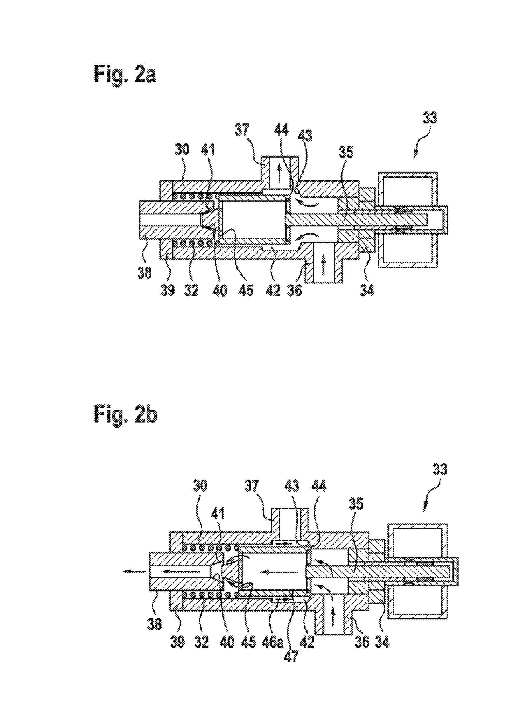
[0023] FIG. 2a shows a first exemplary embodiment of a bypass, controlled by a valve, of the working fluid circuit past an expansion machine in a first switching position,
[0024] FIG. 2b shows a first exemplary embodiment of a bypass, controlled by a valve, of the working fluid circuit past an expansion machine in a second switching position,
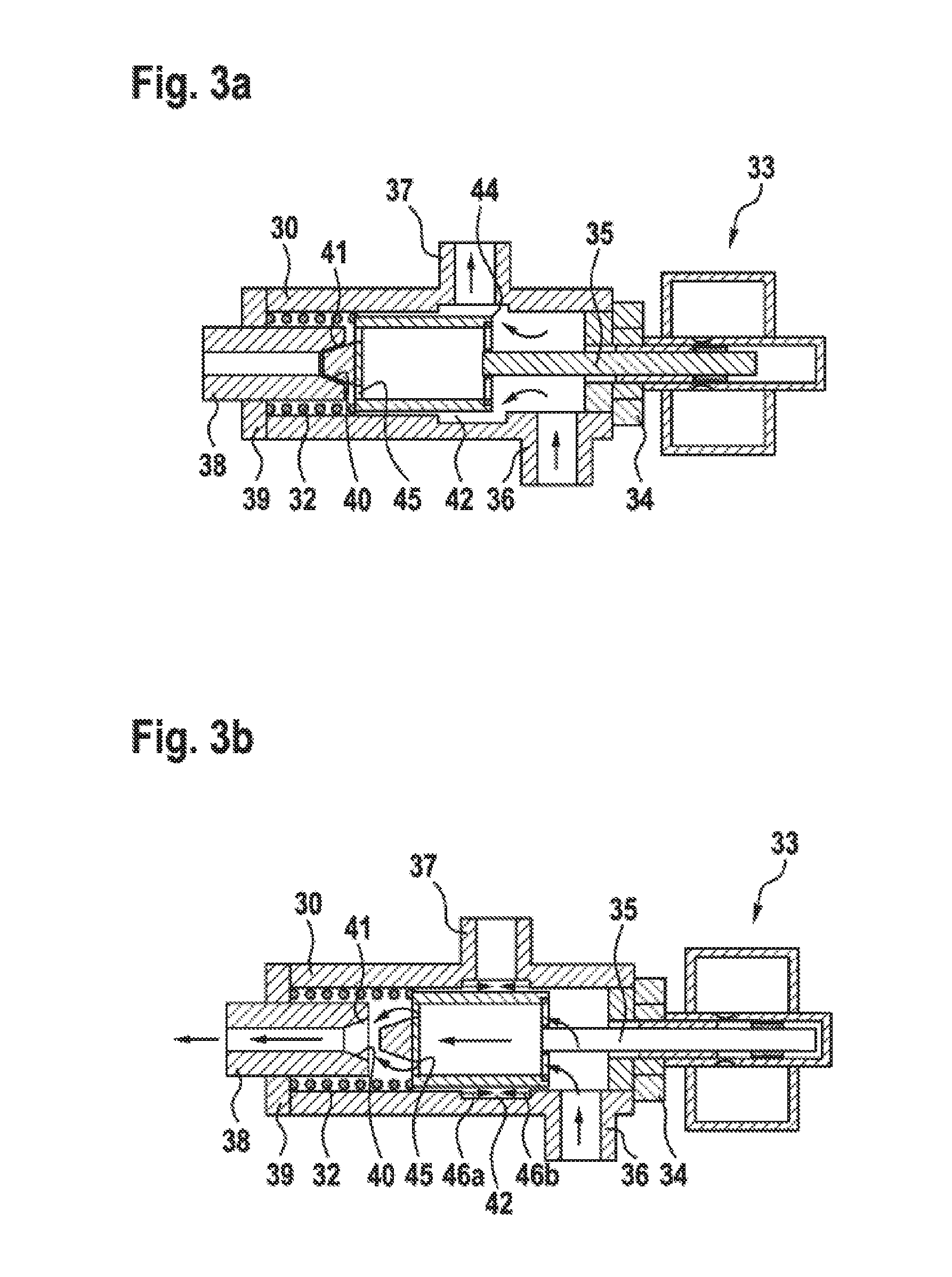
[0025] FIG. 3a shows a second exemplary embodiment of a bypass, controlled by a valve, of the working fluid circuit past an expansion machine in a first switching position,
[0026] FIG. 3b shows a second exemplary embodiment of a bypass, controlled by a valve, of the working fluid circuit past an expansion machine in a second switching position.
DETAILED DESCRIPTION
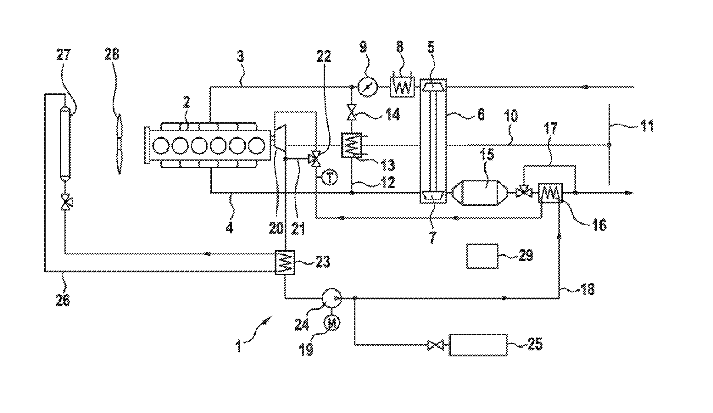
[0027] FIG. 1 shows a waste-heat recovery system 1, which is installed on an internal combustion engine 2 which has a cooling system (not illustrated in any more detail). The internal combustion engine 2 furthermore has a fresh-gas line 3 and an exhaust-gas line 4. Via the fresh-gas line 3, the internal combustion engine 2 is supplied with combustion air which, in the exemplary embodiment, is compressed by a compressor 5 of an exhaust-gas turbocharger 6, which in turn is driven by a turbine 7 incorporated into the exhaust-gas line 4. A charge-air cooler 8 and a throttle flap 9 are connected downstream of the compressor 6.
[0028] The fresh gas supplied to individual combustion chambers of the internal combustion engine 2 with a simultaneous supply of fuel, for example diesel fuel, burns in the combustion chambers of the internal combustion engine 2, generating working power, which is output, for example via an output shaft 10 which is connected to the crankshaft of the internal combustion engine 2 via a transmission, to a drive axle 11, by means of which an arbitrary vehicle in which the internal combustion engine 2 is installed is driven. Via the exhaust-gas line 4, the mixture of fuel and fresh gas burned in the combustion chambers of the internal combustion engine 2 is ultimately discharged as hot gas into the surroundings. The exhaust-gas line 4 is connected to the fresh-gas line 3 via an exhaust-gas recirculation line 12 with, incorporated therein, an exhaust-gas recirculation cooler 13 and an exhaust-gas recirculation valve 14. Via the exhaust-gas recirculation line 12, exhaust gas is recirculated in controlled fashion into the fresh-gas line 3, in particular in order to reduce the harmful exhaust-gas emissions. Downstream of the turbine 7, an exhaust-gas aftertreatment device 15 is likewise provided for reducing the harmful exhaust-gas emissions. Further downstream, a heat exchanger in the form of a superheater 16 of the waste-heat recovery system 1 is incorporated into the exhaust-gas line 4, which heat exchanger can be bypassed in controlled fashion via an exhaust-gas line bypass 17. The superheater 16 is incorporated into a working fluid circuit 18 of the waste-heat recovery system 1--as will be discussed in more detail below.
[0029] The internal combustion engine 2 has the abovementioned cooling system with a coolant circuit, which is however of no further importance of the subject matter of the invention and is therefore not illustrated. The cooling system serves for the cooling of the internal combustion engine 2 and has a coolant cooler incorporated into the cooling circuit and a coolant pump. The coolant pump conveys the coolant through cooling chambers of the internal combustion engine 2 into the coolant cooler, which is connected at the outlet side to the suction side of the coolant pump. Also suitably incorporated into said coolant circuit are, for example, a lubricating oil heat exchanger, a retarder heat exchanger, the charge-air cooler 8 and the exhaust-gas recirculation cooler 13.
[0030] Returning to the waste-heat recovery system 1, the latter has the working fluid circuit 18 with the superheater 16 incorporated into the exhaust-gas line 4. Also incorporated into the working fluid circuit 18 is an expansion machine 20 which is driven by the working fluid changed into the gaseous state in the superheater 16, with expansion of said fluid, and which outputs working power to the internal combustion engine 2 or to some other machine, for example a generator. Here, the expansion machine 20 can be bypassed via a working fluid bypass 21, which is controlled by a directional valve 22 formed preferably as a 3/2 directional valve. Furthermore, a condenser 23 is incorporated into the working fluid circuit 18 downstream of the expansion machine 20, in which condenser the working fluid is normally cooled down into the liquid state and is subsequently supplied to a working fluid pump 24. The working fluid pump 24 is for example electrically driven by a motor 19 and conveys the cooled-down working fluid back to the superheater 16. Here, at the outlet side of the working fluid pump 24, a pressure compensation tank 25 is incorporated into the working fluid circuit 18.
[0031] The abovementioned condenser 23 is in turn a constituent part of a working fluid cooling circuit 26, which furthermore has a cooler 27. The cooler 27 is for example arranged upstream or downstream of the coolant cooler and is flowed through by a cooling air flow which is conveyed for example by a fan 28, which is driven directly or indirectly by the internal combustion engine 2. Finally, an electric or electronic control device 29 is provided, which controls the waste-heat recovery system 1 including possibly the entire internal combustion engine 2. Said control device 29 also serves for controlling the 3/2 directional valve 22 of the waste-heat recovery system 1, which valve will be discussed in more detail with regard to its design and function in the following figures.
[0032] FIG. 2a shows the directly controlled 2/3 directional valve 22, which is pressure-balanced at least in one switching position, in a first embodiment, and shows a switching position in which the working fluid of the working fluid circuit 18 is conducted to the expansion machine 20. By contrast, in the switching position of the 3/2 directional valve 22 illustrated in FIG. 2b, the working fluid is conducted to the working fluid bypass 21 and thus so as to bypass the expansion machine 20. The 3/2 directional valve 22 has a cylindrical tubular slide housing 30 in which a slide 31 of piston-like form is adjustable axially counter to the force of a spring 32. Said adjustment movement is effected by an actuator 33 which is fixedly connected by means of an actuator holding device 34 to the slide housing 30 and which has an actuator switching rod 35, which in turn is connected to the slide 31 for the direct axial adjustment of the slide 31. For example, the actuator 33 is formed as an electromagnet and, when electrically energized, moves the actuator switching rod 35 with the slide 31 into the position illustrated in FIG. 2a, whereas, when electrically deenergized, the position of the slide 31 illustrated in FIG. 2b is set by means of the restoring force of the spring 32. The actuator 33 may however also for example be of pneumatic, hydraulic or electromagnetic form in other embodiments.
[0033] The slide housing 30 has a tubular and flange-mounted fluid inlet 36, which is connected to the working fluid circuit 18 at the outlet side of the superheater 16. Furthermore, the slide housing 30 has a likewise tubular expansion machine fluid outlet 37, which is connected directly or indirectly to the flow inlet into the expansion machine 20. The expansion machine fluid outlet 37 may, like the fluid inlet 36, be configured as a metallic pipe connection piece, which is welded to the slide housing 30, the latter likewise being manufactured from a metallic material. Furthermore, the 3/2 directional valve 22 has a bypass fluid outlet 38, which is connected to the working fluid bypass 21. The bypass fluid outlet 38 is arranged on a closure plate 39, opposite the actuator holding device 34, on the slide housing 30, or is a constituent part of the closure plate 39 and formed for example as a bypass fluid outlet pipe with a throttling action set by means of the pipe diameter.
[0034] The bypass fluid outlet 38 or the bypass fluid outlet pipe has a bypass fluid outlet seat 40, in which an end-side facing slide seat 41 of the slide 31 can be engaged with sealing action and thus in leakage-free fashion. The slide seat 41 is arranged on, or formed in one piece with, a slide base wall of the slide 31 of piston-like form, wherein the slide base wall has passage openings 45 for an unhindered throughflow of the working fluid.
[0035] The corresponding switching position is illustrated in FIG. 2a. In this switching position, the working fluid flowing into the 3/2 directional valve 22 or the slide housing 30 via the fluid inlet 36 flows in leakage-free fashion into the expansion machine fluid outlet 37 in accordance with the illustrated flow arrows. In the region of the expansion machine fluid outlet 37, an encircling ring-shaped groove 42 is recessed into the slide housing 30, which ring-shaped groove promotes an unhindered flow through the 3/2 directional valve 22 and, at the same time, in the direction of the actuator holding device 34, transitions into an expansion machine fluid outlet seat 43 adjacent to the fluid inlet 36.
[0036] The slide 31 is displaceable with an encircling slide edge 44 into the expansion machine fluid outlet seat 43, which is formed for example by a cylindrical pipe diameter reduction of the slide housing 30. The corresponding switching position is, as stated above, illustrated in FIG. 2b. In this switching position, the direct passage from the fluid inlet 36 via the expansion machine outlet seat 43 and the ring-shaped groove 42 into the expansion machine outlet 37 is blocked. At the same time, it is however the case that the working fluid flows, in accordance with the illustrated flow arrows, through the slide 31 of piston-like form, and passes via the passage openings 45 directly into the bypass fluid outlet 38, because, in this switching position, the slide seat 41 has been moved out of the bypass fluid outlet seat 40 and opens up a flow connection.
[0037] At the same time, in this switching position, a small leakage of the maximum volume flow of the working fluid from the fluid inlet 36 to the expansion machine fluid outlet 37 is set, which is set by means of the play with which the slide 31 is guided in the slide housing 30. Here, the defined leakage quantity 46a of the working fluid passes from the slide seat 41 back to the expansion machine fluid outlet 37. Alternatively (in the case of play-free guidance of the slide 31 in the slide housing 30) or in addition, it is also possible for at least one leakage throttle bore 47a, illustrated only in FIG. 2b, to be provided in the slide 31 in the region of the ring-shaped groove 42. The leakage quantity 46a of the working fluid is less than 10% of the maximum volume flow, preferably less than 1% of the maximum volume flow.
[0038] The exemplary embodiment as per FIGS. 3a, 3b differs from that of FIGS. 2a, 2b in that, here, no expansion machine fluid outlet seat 43 is provided into which a slide edge 44 could engage in the switching position as per FIG. 3b. In this exemplary embodiment, the slide housing 30 is formed with a shoulder-free internal diameter. Thus, it is also the case in the switching position as per FIG. 3b (the switching position is identical to that of FIG. 2a at least in terms of function) that a leakage quantity 46b flows from said side from the fluid inlet 36 into the expansion machine fluid outlet 37. In this embodiment, too, the entire leakage quantity 46a, 46b of the working fluid is less than 10% of the maximum volume flow, preferably less than 1% of the maximum volume flow. Furthermore, in this embodiment, the switching travel to be covered by the actuator 33 is longer than in the exemplary embodiment as per FIGS. 2a, 2b.
[0039] It is finally pointed out that any design details illustrated in the figures may be combined with one another within the scope of the invention.
* * * * *
D00000
D00001
D00002
D00003
XML
uspto.report is an independent third-party trademark research tool that is not affiliated, endorsed, or sponsored by the United States Patent and Trademark Office (USPTO) or any other governmental organization. The information provided by uspto.report is based on publicly available data at the time of writing and is intended for informational purposes only.
While we strive to provide accurate and up-to-date information, we do not guarantee the accuracy, completeness, reliability, or suitability of the information displayed on this site. The use of this site is at your own risk. Any reliance you place on such information is therefore strictly at your own risk.
All official trademark data, including owner information, should be verified by visiting the official USPTO website at www.uspto.gov. This site is not intended to replace professional legal advice and should not be used as a substitute for consulting with a legal professional who is knowledgeable about trademark law.