Ceramic Matrix Composite Turbine Component With Graded Fiber-reinforced Ceramic Substrate
Subramanian; Ramesh ; et al.
U.S. patent application number 16/076922 was filed with the patent office on 2019-02-14 for ceramic matrix composite turbine component with graded fiber-reinforced ceramic substrate. This patent application is currently assigned to Siemens Aktiengesellschaft. The applicant listed for this patent is Siemens Aktiengesellschaft. Invention is credited to Christian Xavier Campbell, Ramesh Subramanian.
| Application Number | 20190048730 16/076922 |
| Document ID | / |
| Family ID | 52589834 |
| Filed Date | 2019-02-14 |


| United States Patent Application | 20190048730 |
| Kind Code | A1 |
| Subramanian; Ramesh ; et al. | February 14, 2019 |
CERAMIC MATRIX COMPOSITE TURBINE COMPONENT WITH GRADED FIBER-REINFORCED CERAMIC SUBSTRATE
Abstract
A ceramic matrix composite ("CMC") component, such as a turbine blade for a combustion turbine engine that has a fiber-reinforced, solidified ceramic substrate. The substrate has an inner layer of fibers, for enhancing structural strength of the component. An outer layer of fibers defines voids therein. A thermal barrier coat ("TBC") is applied over and coupled to the outer layer fibers, filling the voids. The voids provide increased surface area and mechanically interlock the TBC, improving adhesion between the fiber-reinforced ceramic substrate and the TBC.
| Inventors: | Subramanian; Ramesh; (Oviedo, FL) ; Campbell; Christian Xavier; (Charlotte, NC) | ||||||||||
| Applicant: |
|
||||||||||
|---|---|---|---|---|---|---|---|---|---|---|---|
| Assignee: | ; Siemens
Aktiengesellschaft Munchen DE |
||||||||||
| Family ID: | 52589834 | ||||||||||
| Appl. No.: | 16/076922 | ||||||||||
| Filed: | May 10, 2016 | ||||||||||
| PCT Filed: | May 10, 2016 | ||||||||||
| PCT NO: | PCT/US2016/031607 | ||||||||||
| 371 Date: | August 9, 2018 |
Related U.S. Patent Documents
| Application Number | Filing Date | Patent Number | ||
|---|---|---|---|---|
| PCT/US2016/018224 | Feb 17, 2016 | |||
| 16076922 | ||||
| PCT/US2015/016318 | Feb 18, 2015 | |||
| PCT/US2016/018224 | ||||
| Current U.S. Class: | 1/1 |
| Current CPC Class: | B22C 7/02 20130101; F05D 2220/32 20130101; F05D 2240/11 20130101; F05D 2250/185 20130101; F01D 5/284 20130101; F05D 2230/00 20130101; F05D 2250/23 20130101; F04D 29/526 20130101; F01D 11/08 20130101; F01D 5/187 20130101; F05D 2250/182 20130101; F05D 2250/60 20130101; F05D 2260/202 20130101; C23C 4/073 20160101; B28B 11/048 20130101; F01D 11/127 20130101; F04D 29/685 20130101; F05D 2250/183 20130101; F05D 2250/12 20130101; F05D 2250/75 20130101; F01D 9/023 20130101; Y02T 50/676 20130101; Y02T 50/6765 20180501; F05D 2250/282 20130101; F01D 5/28 20130101; Y02T 50/672 20130101; F05D 2250/184 20130101; F05D 2260/22141 20130101; C23C 4/18 20130101; F01D 5/18 20130101; F01D 5/186 20130101; F01D 25/12 20130101; C23C 28/3215 20130101; F01D 5/288 20130101; F05D 2230/30 20130101; F05D 2300/175 20130101; B22D 25/02 20130101; B28B 19/0015 20130101; F05D 2250/15 20130101; B22D 29/001 20130101; F05D 2230/90 20130101; F05D 2250/294 20130101; Y02T 50/60 20130101; F05D 2230/211 20130101; F05D 2230/31 20130101; F05D 2250/292 20130101; Y02T 50/673 20130101; C23C 4/02 20130101; B22C 9/24 20130101; C23C 28/3455 20130101; F01D 11/122 20130101 |
| International Class: | F01D 5/28 20060101 F01D005/28; B28B 11/04 20060101 B28B011/04; B28B 19/00 20060101 B28B019/00 |
Claims
1. A ceramic matrix composite ("CMC") component for a combustion turbine engine, comprising: a fiber-reinforced ceramic substrate, having: an inner layer fibers, for enhancing structural strength of the component, and an outer layer of fibers outboard of the inner layer, the outer layer comprising voids therein defined by a spacing distance between adjacent fibers of the outer layer; and a thermally sprayed or vapor deposited or solution/suspension plasma sprayed thermal barrier coat ("TBC"), including a TBC inner surface applied over and coupled to the outer layer fibers, filling the voids there between, and a TBC outer surface for exposure to combustion gas.
2. The engine component of claim 1, the outer layer fibers defining a textured surface profile, having height variation greater than the diameter of any single fiber, or bundle of fibers therein, for increasing contact surface area with the TBC inner surface.
3. The engine component of claim 2, further comprising fiber strands projecting outwardly away from an outer surface of a pattern that is defined by the outer layer fibers, for increasing contact surface area with the TBC inner surface.
4. The engine component of claim 2, further comprising fiber strand loops projecting outwardly away from an outer surface of a pattern that is defined by the outer layer fibers, for increasing contact surface area with the TBC inner surface.
5. The engine component of claim 2, the TBC outer surface having engineered groove features ("EGFs").
6. The engine component of claim 1, the TBC thickness between 0.5 mm to 2 mm.
7. The engine component of claim 2, a textured surface profile height in the outer fiber layer varying between 0.1 to 1.5 mm, with the voids in the outer fiber layer defined by a spacing distance between individual fibers or fiber bundles of 0.1 mm to 8 mm.
8. The engine component of claim 2, further comprising an intermediate layer of fibers interposed between the inner and outer fiber layers, having a fiber pattern that defines a density and cross sectional area less than those of the inner fiber layer pattern, and greater than those of the outer fiber layer.
9. The engine component of claim 1, further comprising a metallic member coupled to fiber-reinforced ceramic substrate, and circumscribed by the inner layer of fibers.
10. The engine component of claim 1, further comprising an intermediate layer of fibers interposed between the inner and outer fiber layers, having a fiber pattern that defines a density and cross sectional area less than those of the inner fiber layer pattern, and greater than those of the outer fiber layer.
11. The engine component of claim 1, the fibers in the fiber-reinforced ceramic substrate comprising: oxide ceramic fibers, glass or glassy fibers, or non-oxide ceramic fibers.
12. The engine component of claim 11, the fibers in the fiber-reinforced ceramic substrate selected from the group consisting of alumina, mullite, mixtures of alumina and mullite, and silicon carbon nitride ("SiCN").
13. A method for manufacturing a ceramic matrix composite ("CMC") component for a combustion turbine engine, comprising: laying-up ceramic fibers into a layered structure, including: an inner layer, for enhancing structural strength of the component, and an outer layer of fibers outboard of the inner layer, the outer layer comprising voids therein defined by a spacing distance between adjacent fibers of the outer layer; and; impregnating the ceramic fibers with ceramic slurry material, if those fibers were not previously impregnated with ceramic material prior to their lay-up; curing the impregnated ceramic fibers, forming a solidified fiber-reinforced ceramic substrate, which defines a ceramic substrate outer surface; and applying a thermally sprayed, or vapor deposited, or solution/suspension plasma sprayed thermal barrier coat ("TBC") over and coupled to the ceramic substrate outer surface.
14. The method of claim 13, further comprising laying-up the outer layer fibers to define a textured surface profile, having height variation greater than the diameter of any single fiber, or bundle of fibers therein, for increasing contact surface area with the TBC inner surface.
15. The method of claim 14, further comprising laying-up the outer layer fibers to define fiber strands projecting outwardly away from an outer surface of a pattern that is defined by the outer layer fibers, for increasing contact surface area with the TBC inner surface.
16. The method of claim 14, further comprising laying-up the outer layer fibers to define fiber strand loops projecting outwardly away from an outer surface of a pattern that is defined by the outer layer fibers, for increasing contact surface area with the TBC inner surface.
17. The method of claim 14, further comprising applying the TBC to a thickness between 0.5 mm to 2 mm.
18. The method of claim 14, further comprising laying-up the textured surface profile in the outer fiber layer with a height between 0.1 mm to 1.5 mm, and with voids in the outer fiber layer defined by a spacing distance between individual fibers or fiber bundles of 0.1 mm to 8 mm.
19. The method of claim 14, further comprising laying-up an intermediate layer of fibers interposed between the inner and outer fiber layers, having a fiber pattern that defines a density and cross sectional area less than those of the inner fiber layer pattern, and greater than those of the outer fiber layer.
20. The method of claim 13, further comprising laying-up an intermediate layer of fibers interposed between the inner and outer fiber layers, having a fiber pattern that defines a density and cross sectional area less than those of the inner fiber layer pattern, and greater than those of the outer fiber layer.
Description
PRIORITY CLAIM
[0001] This application claims priority to International Application No. PCT/US16/18224, filed Feb. 17 2016, and entitled "CERAMIC MATRIX COMPOSITE TURBINE COMPONENT WITH ENGINEERED SURFACE FEATURES RETAINING A THERMAL BARRIER COAT", which claims priority to and the benefit of International Application No. PCT/US15/16318, filed Feb. 18, 2015, and entitled "TURBINE COMPONENT THERMAL BARRIER COATING WITH CRACK ISOLATING ENGINEERED GROOVE FEATURES", the entire contents of which are incorporated by reference herein.
TECHNICAL FIELD
[0002] The invention relates to components for combustion turbine engines, with ceramic matrix composite ("CMC") structures that are in turn insulated by a thermal barrier coating ("TBC"), and methods for making such components. More particularly, the invention relates to engine components for combustion turbines, with ceramic matrix composite ("CMC") structures, having graded fiber-reinforced ceramic substrates. An inner layer fiber pattern provides structural support for the component and an outer layer fiber pattern anchors the TBC to the CMC structure.
BACKGROUND
[0003] CMC structures comprise a solidified ceramic substrate, in which are embedded ceramic fibers. The embedded ceramic fibers within the ceramic substrate of the CMC improve elongation rupture resistance, fracture toughness, thermal shock resistance, and dynamic load capabilities, compared to ceramic structures that do not incorporate the embedded fibers. The CMC embedded fiber orientation also facilitates selective anisotropic alteration of the component's structural properties. CMC structures are fabricated by laying-up or otherwise orienting ceramic fibers, also known as "rovings", into fabrics, filament windings, tows, or braids. Fiber-reinforced ceramic substrate fabrication for CMCs is comparable to what is done to form fiber-reinforced polymer structural components for aircraft wings or boat hulls. Unless the ceramic fibers are pre-impregnated with a resin containing ceramic material, they are subsequently impregnated with ceramic material by such techniques as gas deposition, melt infiltration, preceramic polymer pyrolysis, chemical reactions, sintering, or electrophoretic deposition of ceramic powders, creating a solid ceramic structure with embedded, oriented ceramic fibers.
[0004] Ceramic matrix composite ("CMC") structures are being incorporated into gas turbine engine components as insulation layers and/or structural elements of such components, such as insulating sleeves, vanes and turbine blades. These CMCs provide better oxidation resistance, and higher temperature capability, in the range of approximately 1150 degrees Celsius ("C") for oxide based ceramic matrix composites, and up to around 1350 C for Silicon Carbide fiber-Silicon Carbide core ("SiC--SiC") based ceramic matrix composites, whereas nickel or cobalt based superalloys are generally limited to approximately 950 to 1000 degrees Celsius under similar operating conditions within engines. While 1150 C (1350 C for SiC--SiC based CMCs) operating capability is an improvement over traditional superalloy temperature limits, mechanical strength (e.g., load bearing capacity) of CMCs is also limited by grain growth and reaction processes with the matrix and/or the environment at 1150 C/1350 C and higher. With desired combustion turbine engine firing temperatures as high as 1600-1700 C, the CMCs need additional thermal insulation protection interposed between themselves and the combustion gasses, to maintain their temperature below 1150 C/1350 C.
[0005] CMCs are receiving additional thermal insulation protection by application of overlayer(s) of thermal barrier coats or coatings ("TBCs"), as has been done in the past with superalloy components. However, TBC application over CMC or superalloy substrates presents new and different thermal expansion mismatch and adhesion challenge. During gas turbine engine operation superalloy, CMC and TBC materials all have different thermal expansion properties. In the case of TBC application over superalloy substrates, the superalloy material expands more than the overlying TBC material, which in extreme cases leads to crack formation in the TBC layer and its delamination from the superalloy surface. Along with thermal mismatch challenges, metallic substrate/TBC interfaces have adhesion challenges. While TBC material generally adheres well to a fresh metallic superalloy substrate, or in an overlying metallic bond coat ("BC") substrate, the metals generate oxide surface layers, which subsequently degrade adhesion to the TBC at the respective layer interface.
[0006] TBC/metallic substrate interface integrity is maintained by use of the inventions in International Application No. PCT/US15/16318, entitled "TURBINE COMPONENT THERMAL BARRIER COATING WITH CRACK ISOLATING ENGINEERED GROOVE FEATURES"; and International Application No. PCT/US15/16331, entitled "TURBINE COMPONENT THERMAL BARRIER COATING WITH CRACK ISOLATING ENGINEERED SURFACE FEATURES", both of which are in the priority chain of this application and which are incorporated by reference during National Phase prosecution in those jurisdictions that allow such incorporation. Some embodiments described in these priority applications incorporate engineered surface features ("ESFs") on the substrate surface of the metallic superalloy substrate, or in an overlying metallic bond coat ("BC"), or a combination in both metallic surfaces. The ESFs at the metal surface/TBC layer interface mechanically anchor the TBC material, to inhibit delamination or at least confine delamination damage to boundaries defined by adjacent ESFs. Other embodiments in the priority applications incorporate engineered groove features ("EGFs") on the TBC layer outer surface, to control surface crack propagation. Additional embodiments in those applications incorporate both ESFs and EGFs. Therefore, as the metal material is heated (forming surface oxides) and expands during engine operation, the lesser expanding TBC material is mechanically interlocked with the metal, despite degradation of interlayer adhesion.
[0007] Turning back to CMC/TBC thermal expansion mismatch and general interlayer adhesion challenges, relative layer expansion is opposite that experienced by superalloy/TBC components. The TBC material tends to expand more than underlying CMC material. As the TBC heats, it tends to lose adhesion with and delaminate from the CMC surface. Many CMC materials already contain oxides in the solidified ceramic core and in their embedded ceramic fibers, which adversely affect inter-layer adhesion at the CMC/TBC interface. In the case of SiC--SiC composites, the thermal barrier coatings can react with the underlying Silicon based matrix to form new chemical compounds, more brittle than the matrix or coating. Therefore, application of the TBC on the CMC surface of the component without subsequent delamination during engine operation is difficult. Depending upon the local macro roughness of the embedded ceramic fibers in the preform, and the infiltration characteristics of the ceramic material, which embed the preform into the solidified ceramic core, the adhesion of TBC coatings, is generally poorer than that of TBC coating on metallic substrates. TBC/CMC adhesion is particularly poor where the ceramic substrate's embedded fibers are oriented parallel to the component surface. TBC layer thickness is limited to that which will maintain adhesion to the CMC surface, despite its higher rate of thermal expansion. In other words, TBC layer thickness is kept below a threshold that accelerates the TBC/CMC thermal expansion delamination, within the already relatively limited bounds of TBC/CMC material adhesion capabilities. Unfortunately, limiting the TBC layer thickness undesirably limits its insulation properties. Generally, a thicker TBC layer offers more insulation protection to the underlying CMC substrate/layer than a thinner layer.
SUMMARY OF INVENTION
[0008] Exemplary embodiments described herein enhance TBC retention on CMC components in combustion turbine engines, by utilizing graded fiber or graded patterned fabric embedded in different zones within the CMC ceramic substrate. Inner fibers, in the more inwardly facing zone of the ceramic substrate provide greater structural strength of the component, than the outer fibers along the outer surface of the substrate, which interface with the TBC layer's inner surface. The outer fiber patterns have anchoring voids between fibers and/or fiber bundles for retention and anchoring of the TBC layer as the latter is applied to the ceramic core. In some embodiments, the outer fiber patterns have textured surfaces, including in some embodiments three-dimensional textured surfaces, for anchoring of the TBC layer within peaks and valley voids formed in the fabric weave. Other embodiments include fiber strands and/or fiber loops that project from the outer fabric weave pattern, for additional TBC layer anchoring. The outer fabric weaves voids and/or textured surface features mechanically interlock the CMC structure, and in particular, the fibers, to the TBC, and provide increased surface area and additional interlocking for interlayer adhesion. Optionally, as described in the incorporated by reference priority document, PCT/US16/18224, filed Feb. 17 2016, and entitled "CERAMIC MATRIX COMPOSITE TURBINE COMPONENT WITH ENGINEERED SURFACE FEATURES RETAINING A THERMAL BARRIER COAT", engineered surface features ("ESFs") are cut into the outer surface ceramic core and fibers of the preform. A thermally sprayed or vapor deposited or solution/suspension plasma sprayed TBC is applied over and coupled to the ceramic substrate outer surface and any cut ESFs. Increased adherence capabilities afforded by the outer fiber pattern voids and/or projections facilitate application of thicker TBC layers to the component, which increases insulation protection for the underlying CMC structure/layer. The increased adhesion surface area and added mechanical interlocking of the respective materials facilitates application of greater TBC layer thickness to the CMC substrate without risk of TBC delamination. The greater TBC layer thickness in turn provides more thermal insulation to the CMC structure, for higher potential engine operating temperatures and efficiency. In some embodiments, the CMC component covers an underlying substrate, such as a superalloy metallic substrate. In other embodiments, the CMC component is a sleeve over a metallic substrate. In other embodiments, the CMC component has no underlying metallic substrate, and provides its own internal structural support within the fiber-reinforced ceramic substrate. In additional embodiments, a plurality of CMC components are joined together to form a larger, composite CMC component, such as a laminated turbine blade or vane. In other embodiments, the CMC component is a unistructural, non-laminated, turbine blade, or vane.
[0009] The CMC component is made by laying-up ceramic fibers into a layered structure, having an inner layer, for structural support, and an outer layer, for TBC anchoring. If the layed-up fabric structure is not already pre-impregnated with ceramic material prior to laying them up, non-impregnated fibers are subsequently infiltrated with ceramic material, forming a solidified ceramic core. The TBC is then applied to the core outer surface. The outer fabric layer voids and projections assist in anchoring the TBC layer to the ceramic substrate's outer surface, in order to resist the aforementioned oxide layer and thermal expansion induced delamination challenges inherent in CMC/TBC components for gas turbine engines.
[0010] Exemplary embodiments feature a ceramic matrix composite ("CMC") component for a combustion turbine engine, which has a solidified ceramic substrate, with ceramic fibers, embedded therein. The fiber-reinforced ceramic substrate has an inner layer of fibers, for enhancing structural strength of the component. The substrate also has an outer layer of fibers outboard of the inner layer, which defines voids therein. A thermally sprayed, or vapor deposited, or solution/suspension plasma sprayed thermal barrier coat ("TBC") is applied over and coupled to the substrate's outer layer fibers, filling the voids. The voids provide increased surface area and mechanically interlock the TBC, improving adhesion between the fiber-reinforced ceramic substrate and the TBC. The TBC outer surface is suitable for combustion gas exposure when installed in an operating gas turbine engine.
[0011] Other exemplary embodiments feature a component for a combustion turbine engine, which component includes a metallic member for structural support. The metallic member is circumscribed by a ceramic matrix composite ("CMC"), such that the inner layer of fibers also circumscribe the metallic member. In some embodiments, the CMC layer also functions as a support substrate, with or without an additional metallic member. The CMC layer includes the solidified ceramic fiber-reinforced substrate, with a substrate inner surface that is shaped to conform to and abut the metallic member's surface profile. In some embodiments, engineered surface features ("ESFs") are cut into the ceramic substrate's outer surface and its outer layer fibers. A thermally sprayed or vapor deposited or solution/suspension plasma sprayed thermal barrier coat ("TBC"), including a TBC inner surface, is applied over and coupled to the ceramic substrate's outer surface, anchored by voids in the outer layer fibers. In some embodiments, the outer layer fibers define a textured, surface profile, having height variation greater than the diameter of any single fiber, or bundle of fibers therein, for increasing contact surface area with the TBC inner surface. In some embodiments, fiber strands or fiber strand loops project outwardly from the second layer, for increasing contact surface area with the TBC inner surface. In other embodiments, an intermediate layer of fibers is interposed between the inner and outer fiber layers. In some embodiments, the intermediate layer has a pattern that defines a third density and cross sectional area less than those of the first layer do, and greater than those of the second layer.
[0012] Other exemplary embodiments feature methods for manufacturing a CMC component for a combustion turbine engine. A three-dimensional preform is fabricated with ceramic fibers. Ceramic fibers are layed-up into a layered structure, which includes an inner layer, for structural strength of the component. The layered structure also has an outer layer of fibers outboard of the inner layer, having a second weave pattern that defines voids therein. In some embodiments, the inner and outer layer fibers are pre-impregnated with ceramic material prior to being layed-up into the layered structure. If not already pre-impregnated with ceramic material, the layered structure is infiltrated with ceramic material, forming a solidified, fiber-reinforced ceramic substrate, which defines a substrate outer surface. A thermally sprayed, or vapor deposited, or solution/suspension plasma sprayed thermal barrier coat ("TBC") is applied over and coupled to the substrate outer surface and its outer layer fibers, filling the voids. The voids provide increased surface area and mechanically interlock the TBC, improving adhesion between the ceramic substrate and the TBC. The TBC outer surface is suitable for combustion gas exposure when installed in an operating gas turbine engine. In some method embodiments, the outer layer fibers have a textured surface profile, having height variation greater than the diameter of any single fiber, or bundle of fibers therein, for increasing contact surface area with the TBC inner surface. In other embodiments, the outer layer fibers have outwardly projecting fiber strands or fiber loops, for increasing contact surface area with the TBC inner surface. In yet other embodiments, the fiber-reinforced ceramic substrate is fabricated with an intermediate layer of fibers interposed between the inner and outer fiber layers, having a third weave pattern that defines a third weave density and cross sectional area less than those of the inner layer weave pattern, and greater than those of the outer layer weave pattern.
[0013] The respective features of the exemplary embodiments of the invention that are described herein may be applied jointly or severally in any combination or sub-combination.
BRIEF DESCRIPTION OF DRAWINGS
[0014] The exemplary embodiments are further described in the following detailed description in conjunction with the accompanying drawings, in which:
[0015] FIG. 1 is a partial axial, cross sectional view of a gas or combustion turbine engine, incorporating one or more CMC components constructed in accordance with exemplary embodiments of the invention;
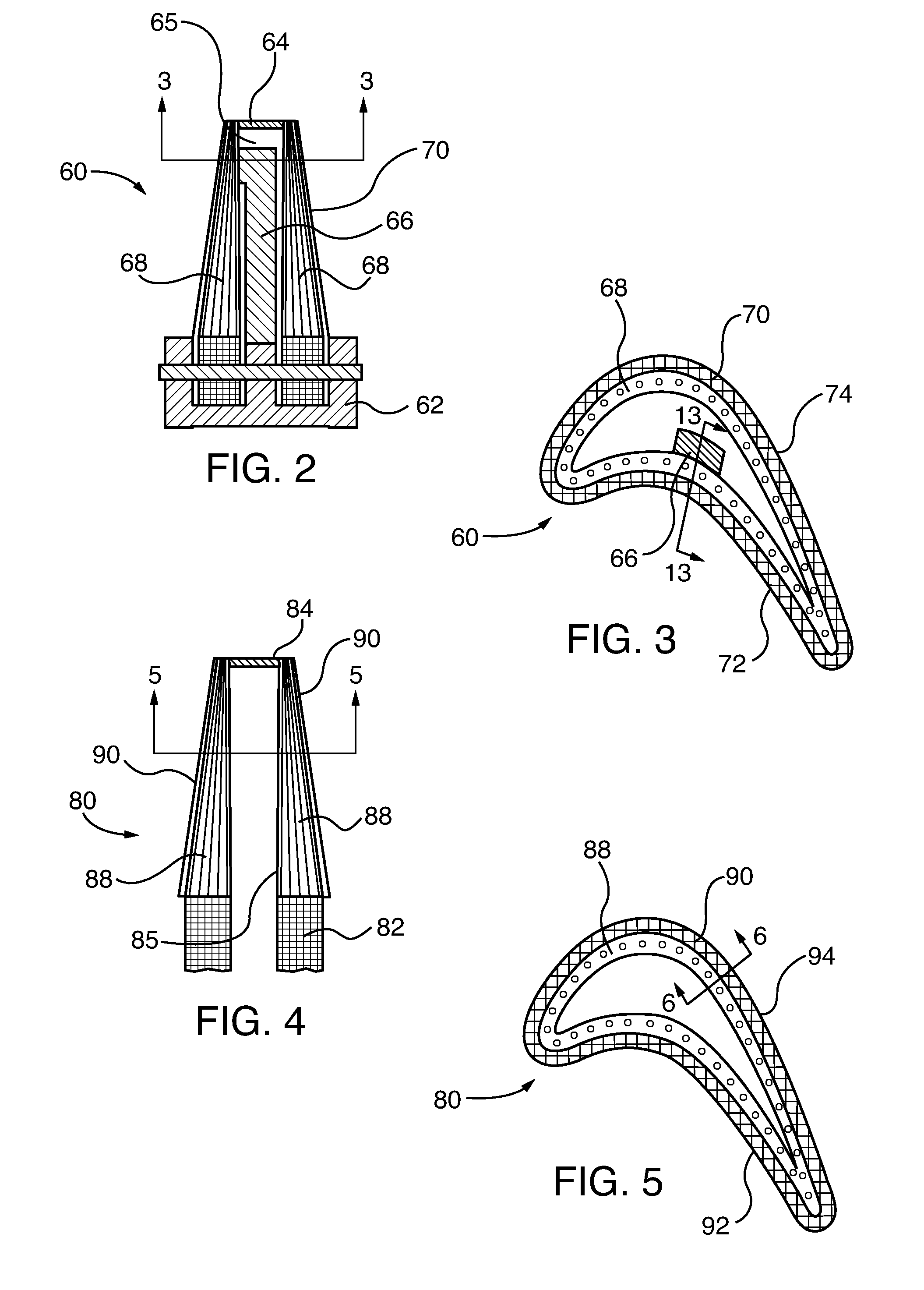
[0016] FIG. 2 is a cross sectional elevation view of a metal reinforced, CMC turbine blade component for a combustion turbine engine, in accordance with an exemplary embodiment of the invention;
[0017] FIG. 3 is a cross sectional plan view of the turbine blade of FIG. 2;
[0018] FIG. 4 is a cross sectional elevation view of another embodiment of a CMC turbine blade component for a combustion turbine engine, which does not have internal metal reinforcement;
[0019] FIG. 5 is a cross sectional plan view of the turbine blade of FIG. 4;
[0020] FIG. 6 is a partial cross sectional elevation view through the side wall of the turbine blade of FIGS. 4 and 5, showing the graded fiber layers that are embedded within the solidified, fiber-reinforced ceramic substrate;
[0021] FIG. 7 is an elevational view of inner layer fibers of the blade side wall of FIG. 6, prior to their incorporation into the fiber-reinforced ceramic substrate, or application of a TBC;
[0022] FIG. 8 is an elevational view of an alternate embodiment of the inner layer fibers of the blade side wall of FIG. 6, prior to their incorporation into the fiber-reinforced ceramic substrate, or application of a TBC;
[0023] FIG. 9 is a detailed elevational view of the inner layer fibers of FIG. 8;
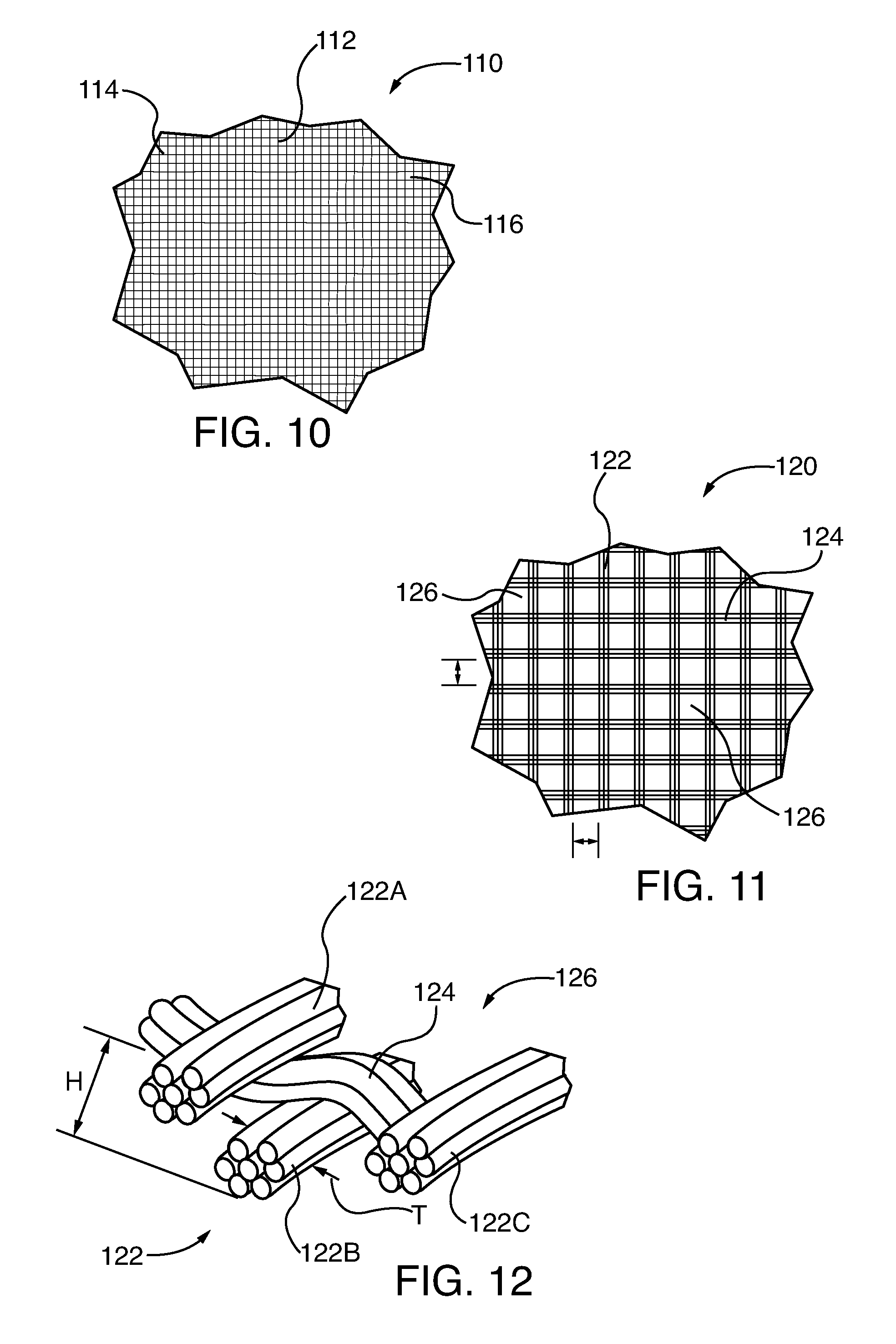
[0024] FIG. 10 is an elevational view of intermediate layer fibers of the blade side wall of FIG. 6, prior to their incorporation into the fiber-reinforced ceramic substrate, or application of a TBC;
[0025] FIG. 11 is an elevational view of outer layer fibers of the blade side wall of FIG. 6, prior to their incorporation into the fiber-reinforced ceramic substrate, or application of a TBC;
[0026] FIG. 12 is a detailed elevational view of the outer layer fibers of FIG. 11;
[0027] FIG. 13 is a partial cross sectional elevation view through the side wall of the turbine blade of FIGS. 2 and 3, showing the blade's metallic support member, and the graded fibers that embedded within the fiber-reinforced ceramic substrate;
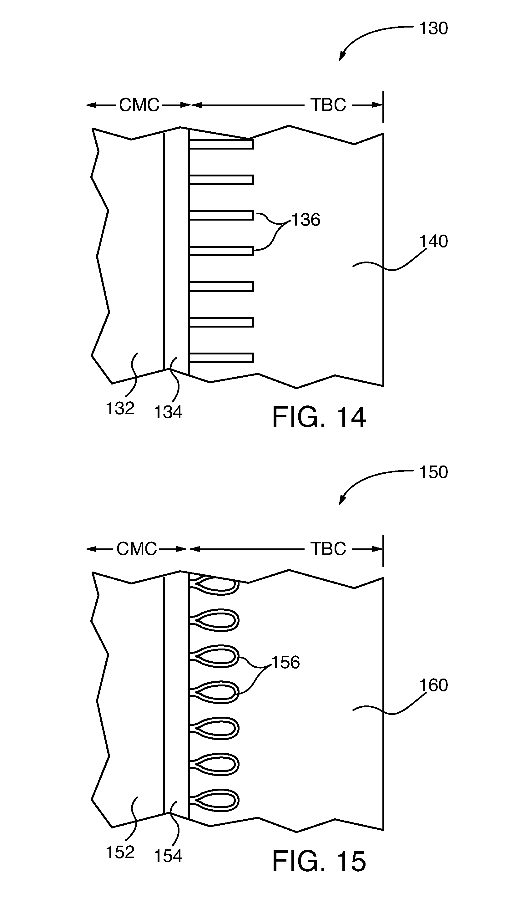
[0028] FIG. 14 is a partial cross sectional elevation view through the side wall of another embodiment of turbine blade, showing fiber strands projecting outwardly from the outer layer fibers, for anchoring the TBC; and
[0029] FIG. 15 is a partial cross sectional elevation view through the side wall of another embodiment of turbine blade, showing fiber loops projecting outwardly from the outer layer fibers, for anchoring the TBC.
[0030] To facilitate understanding, identical reference numerals have been used, where possible, to designate identical elements that are common to the figures. The figures are not drawn to scale.
DESCRIPTION OF EMBODIMENTS
[0031] Exemplary embodiments herein are utilized in combustion turbine engines. Embodiments of the CMC components of the invention are combined to form composite structures, such as turbine blades or vanes, which are structurally self-supporting. In other embodiments, the CMC components cover other structural elements, such as internal metallic (e.g., superalloy metal) members, including by way of example structural reinforcement ribs or other types of supports. In some embodiments, the ceramic matrix composite ("CMC") components of the invention are utilized as insulative covers or sleeves for other structural components, such as metallic superalloy components or other types of metallic support members. In other embodiments, the CMC component is entirely structurally self-supporting, relying on internally embedded fibers to provide additional strength to its fiber-reinforced, ceramic substrate. Embodiments of the CMC components of the invention have a solidified, fiber-reinforced ceramic substrate, with ceramic fibers embedded therein. The fiber-reinforced ceramic substrate utilizes a graded fiber or graded patterned fabric embedded in different zones within the CMC substrate. Inner fibers in the more inwardly facing zone of the ceramic substrate have relatively higher fiber density and cross section, for greater structural support of the component, than the outer fibers along the outer surface of the core, which interface with the TBC layer's inner surface. The outer fiber patterns have voids between fibers and/or fiber bundles for retention and anchoring of the TBC layer as the latter is applied to the fiber-reinforced ceramic substrate. In some embodiments, the outer fiber patterns have textured surfaces, including in other embodiments textured three-dimensional surfaces, for anchoring of the TBC layer within peaks and valley voids, or fiber-spacing voids formed in the fabric pattern or weave. Other embodiments include fiber strands and/or fiber loops that project from the outer fabric pattern or weave (including by further example knitted fabric weaves), for additional TBC layer anchoring. The outer fabric voids and surface features mechanically interlock the CMC structure, and in particular, the fibers, to the TBC, and provide increased surface area and additional interlocking for interlayer adhesion. In some embodiments, engineered surface features ("ESFs") are cut into an outer surface of the fiber-reinforced ceramic substrate. A thermally sprayed or vapor deposited or solution/suspension plasma sprayed TBC is applied over and coupled to the fiber-reinforced ceramic substrate's outer surface and any cut ESFs.
[0032] The outer fabric layer voids and surface features provide increased surface area, and mechanically interlock the TBC, improving adhesion between the ceramic fiber-reinforced ceramic substrate and the TBC. The mechanical interlocking and improved adhesion afforded by the voids and surface features within the outer fabric layer facilitate application of relatively thick TBC layers, from 0.5 mm to 2.0 mm. Because of the thick TBC application, embodiments of the CMC components of the invention are capable of operation in combustion environments up to 1950 degrees Celsius, with the thick TBC limiting the CMC ceramic core temperature to below 1150/1350 degrees Celsius.
[0033] In accordance with method embodiments of the invention, the CMC component is made by laying-up ceramic fibers into a layered structure. If the ceramic fibers are not already pre-impregnated with ceramic material prior to their laying-up, they are subsequently infiltrated with ceramic material, forming a solidified, fiber-reinforced ceramic substrate. In some embodiments, engineered surface features ("ESFs") are cut into the ceramic substrate's outer surface and its outer layer fibers. The TBC is then applied to the ceramic substrate's outer surface and any ESFs. If the CMC component is structurally self-supporting, the ceramic substrate's inner fabric layer provides structural support to the component, such as a blade or vane of a gas turbine engine. If the CMC component is an insulative cover for another structural component, such as a metallic member, superalloy substrate, the component is dimensioned to cover, or otherwise circumscribe, the metallic member. In some applications, the CMC component or a plurality of CMC components are configured as insulative sleeves to cover the metallic member. In some embodiments, a plurality of such sleeves are stacked and laterally joined over a metallic member or other metallic substrate, prior to TBC application. In other embodiments, the CMC component is a unistructural, self-supporting blade, or vane for a gas turbine engine.
[0034] FIG. 1 shows a gas turbine engine 20, having a gas turbine casing 22, a multi-stage compressor section 24, a combustion section 26, a multi-stage turbine section 28 and a rotor 30. One of a plurality of basket-type combustors 32 is coupled to a downstream transition 34 that directs combustion gasses from the combustor to the turbine section 28. Atmospheric pressure intake air is drawn into the compressor section 24 generally in the direction of the flow arrows F along the axial length of the turbine engine 20. The intake air is progressively pressurized in the compressor section 24 by rows rotating compressor blades 50 and directed by mating compressor vanes 52 to the combustion section 26, where it is mixed with fuel and ignited. The ignited fuel/air mixture, now under greater pressure and velocity than the original intake air, is directed through a transition 34 to the sequential vane 56 and blade 50 rows in the turbine section 28. The engine's rotor 30 and shaft retains the plurality of rows of airfoil cross sectional shaped turbine blades 54. Embodiments of the CMC components described herein are designed to operate in engine temperature environments of up to 1950 degrees Celsius. In some embodiments, the CMC components are insulative sleeves or coverings for metallic members, including metallic-substrate structural components, such as the subcomponents within the combustors 32, the transitions 34, the blades 54, or the vanes 56. In other embodiments, the CMC components of the invention are structurally self-supporting, without the need for metallic members or other supporting metallic substrates. Exemplary self-supporting CMC components include compressor blades 50 or vanes 52 (which do not necessarily require the insulation of a TBC, internal subcomponents of combustors 32 or transitions 34). In some embodiments, entire turbine section 28 blades 54 or vane 56 airfoils are CMC structures; with outer surfaces of their fiber-reinforced ceramic substrates having surface textures, through use of graded fabrics, that mechanically interlock a relatively thick TBC layer of 0.5 to 2.0 mm.
[0035] A schematic cross section of an exemplary engine component, a turbine blade 60, is shown in FIGS. 2 and 3. The turbine blade 60 has a blade root 62 for affixation to the turbine engine's rotor 30 and a distal blade tip 64. The blade internal side wall 65 includes a metallic member, which is a metallic reinforcement rib 66. The rib 66 is covered or otherwise circumscribed by a CMC, fiber-reinforced ceramic substrate 68. Internal structural details of the internal core within the turbine blade 60 are known, and for brevity are not shown or described in detail. The ceramic substrate 68 includes graded ceramic fibers embedded therein, which are described in detail below. A thermally sprayed or vapor deposited or solution/suspension plasma sprayed thermal barrier coat ("TBC") 70 is applied over and coupled to the substrate 68 outer surface about the blade side wall pressure side 72 and its suction side 74, including the leading and trailing edges.
[0036] The turbine blade 80 embodiment of FIGS. 4 and 5 has a blade root 82, blade tip 84, and a self-supporting, CMC fiber-reinforced ceramic substrate 88, which form the blade airfoil side wall, including the internal side wall 85 and an outer portion onto which is applied a TBC 90. The turbine blade 80 has no internal metallic ribs or other support structure to carry loads imparted on the blade's pressure side 92 or suction side 94. The self-supporting CMC, fiber-reinforced ceramic substrate 88 utilizes graded fibers for performing localized structural functions. Some fibers are primarily incorporated for structural strength within the CMC ceramic substrate, while others are primarily incorporated for anchoring the TBC layer 90. In this embodiment, the fibers forming the layered structure of the CMC fiber-reinforced ceramic substrate 88 are incorporated into sheets of fabric, which in some embodiments are stacked in layers or plies, and wrapped about the blade, i.e., outboard of the boundaries of the internal side wall 85, during blade fabrication, analogous to a cigar wrapper. Generally, fiber orientation within the fiber structures, which are embedded within fiber-reinforced ceramic substrate 88, incorporate one or more of woven fibers (two- or three-dimensional weaves, including knit weaves), braided fibers (including tows of braided fibers), and/or uniaxial fibers.
[0037] The graded fabric plies, which are incorporated into the layered structure of the fiber-reinforced ceramic substrate 88, are shown schematically in FIG. 6. The description that follows with respect to FIG. 6 is also applicable to FIG. 13. The schematic of FIG. 13, directed to the blade embodiment of FIGS. 2 and 3, incorporates the metal member, blade-reinforcing rib 66, but is otherwise identical to FIG. 6. For simplicity, a plane view of each exemplary type of fabric sheet within the ceramic core 88 is shown in FIG. 6.
[0038] Referring to FIGS. 6 and 7, an inner layer of parallel fibers, such as the woven fabric fibers shown therein, have a first weave pattern 100 that defines a first weave density and cross sectional area, providing structural strength to the component ceramic substrate 88 of the blade component 80. The primary function of the inner layer fibers is to provide structural support to the ceramic substrate 88 and the overall blade component 80. The shown inner layer weave pattern has parallel vertical or axially oriented fibers 102 that are woven in bundles or tows 112, which enhance axial and torsional tensile strength of the blade component 80. The inner layer weave pattern 100 also has horizontal fibers 104, which maintain parallel orientation of the vertical/axially-oriented fibers 102. The vertical fibers 102 are tightly packed in the horizontal direction of FIG. 7, with no intentional spacing between them. In the alternative embodiment of FIGS. 8 and 9, the inner layer fabric 100A has a tight, flat weave fiber pattern, with an equal distribution and density of vertical fibers 102A and horizontal fibers 104A. Both the embodiments 100 and 100A for the inner layer fabric weave have relatively flat surface profiles. As previously noted, such flat weave profiles do not promote good bonding with TBC overlays, leaving the TBC susceptible to separation from the fiber-reinforced ceramic substrate 88 during thermal expansion or from relatively poor oxide bonding between the ceramic substrate 88 and the TBC material 90. Therefore, the embodiments 100 and 100A of the inner layer fiber weave are less than optimal for use in the outermost layer of a fiber-reinforced ceramic substrate, such as the turbine blade ceramic substrate 88. However, the embodiments described herein incorporate graded fibers in the fiber-reinforced ceramic substrate 88, which vary orientation locally within the substrate, and which are chosen for their structural and functional suitability.
[0039] Referring to FIGS. 6 and 10, the fiber-reinforced ceramic substrate 88 incorporates an intermediate layer of fibers, such as the woven fiber fabric 110, which are outboard of the inner woven fiber layer(s) 100. The intermediate layer 110 has a weave pattern that defines a weave density and cross sectional area, less than those of the first weave pattern 100 do. The intermediate layer comprises vertical fibers (one or more fibers alone or in bundles/tows) 112, with lateral spacing distance S2, and horizontal fibers 114 (one or more fibers alone or in bundles/tows), with vertical spacing S1. Voids 116 are formed between the spaced fibers 112 and 114, facilitating bonding and structural integrity within the CMC ceramic core 88.
[0040] As shown in FIGS. 6, 11 and 12, an outer layer of fibers, such as the fabric woven fibers 120 is oriented in the CMC component's fiber-reinforced ceramic substrate 88, outboard of the inner layer 100 and the intermediate layer 110. In some embodiments, scrim fabric, which generally comprises an open fiber grid of non-woven, fused fibers, is used to form the outer layer fibers 120. In the embodiments of FIGS. 6, 11 and 12, the outer layer fibers 120 have a weave pattern that defines a weave density and cross sectional area less than those of the inner layer weave pattern 100 or the intermediate layer weave pattern 110. This outer layer 120 employs a textured surface, with a weave pattern of vertical fibers 122 (one or more fibers alone or in bundles/tows, or a non-woven, scrim-type fabric), with lateral spacing distance S4, and horizontal fibers 124 (one or more fibers alone or in bundles/tows, or in scrim fabric fused fibers), with vertical spacing S3. In some embodiments, the spacing S3 or S4 between fibers is between 0.1 mm to 8 mm. Voids 126 are formed between the net-like array of spaced fibers 122 and 124, facilitating bonding and structural integrity within the CMC ceramic core 88 and the TBC layer 90.
[0041] As shown in the embodiment of FIG. 12, the three-dimensional, textured weave also creates vertical gaps or voids 126 of radial distance or height H, between the fiber strands 122A, 122B, and 122C, in addition to the net-like voids 126 formed between fibers in the open spacing distances S3 and S4. In some embodiments, vertical voids in the outer fiber layer defined by spacing between individual fibers or fiber bundles of textured surface profile height H in the outer fiber layer 120, varies between 0.1 to 1.5 mm. In this embodiment, the height H within the outer fiber layer 120 is greater than diameter T of any single fiber, or bundle of fibers that form the layer. The vertical and horizontal voids or gaps create spaces for embedding and anchoring of the TBC, as it is applied to the CMC component's fiber-reinforced ceramic substrate 88. Given the lesser weave density and cross sectional area of the outer fabric layer 120, as compared to the inner layer 110, the former provides less structural strength to the CMC turbine blade component 80 and its ceramic substrate 88, but it provides considerably more surface area and voids for anchoring of the TBC layer 90.
[0042] A thermally sprayed or vapor deposited or solution/suspension plasma sprayed thermal barrier coat ("TBC") 90 is applied over and coupled to the CMC ceramic substrate 88 outer surface and its outer fabric layer 120. The TBC 90 bonds and anchors to the outer fabric layer 120, with its relatively large surface area along the bonding zone, compared to a relatively flat planar bonding zone, which would otherwise be formed by the weave pattern of the inner layer fabric 110. Experience has shown that TBC tends to delaminate and spall from a flat CMC outer surface, especially if the reinforcing fibers, such as those of the inner fabric layer 110, are oriented parallel to the CMC ceramic substrate 88 outer surface. In embodiments herein, the voids or interstices 126, including the exemplary three-dimensional voids and interstices, skew orientation of the fibers 122 and 124 relative to the TBC layer 90, which creates abutting interfaces, rather than the parallel interfaces of the inner fabric layer 110. Optional engineered groove features (EGFs) 91 are cut into the TBC outer surface.
[0043] Referring to the component embodiments of FIGS. 14 and 15, TBC adhesion to the CMC component's fiber-reinforced ceramic substrate is enhanced by bonding between the TBC material and fibers that project from the outer fabric layer outer surface. In FIG. 14, the component 130 CMC component's fiber-reinforced ceramic substrate 132 has an outer layer fiber pattern 134, with fiber strands 136 projecting from the outer layer. Cutting ceramic fiber strands in non-structural load bearing outer layer fabric 134 peripheral zones of the CMC component's ceramic substrate 132 does not impair structural integrity of the CMC component 130. The fiber strands 136 provide additional anchoring for the TBC layer 140.
[0044] Referring to FIGS. 6 and 13, optional engineered groove features ("EGFs") 71, 91 are cut into the respective TBC 70, 90 outer surfaces, as described in the incorporated by reference priority International Application No. PCT/US16/18224, filed Feb. 17 2016, and entitled "CERAMIC MATRIX COMPOSITE TURBINE COMPONENT WITH ENGINEERED SURFACE FEATURES RETAINING A THERMAL BARRIER COAT". In some embodiments, as described in the priority documents, the EGFs 71, 91 are cut in pattern arrays, including pattern arrays that intersect engineered surface features ("ESFs") of the CMC ceramic core, for enhanced spallation isolation. In embodiments of the priority document, the CMC ceramic substrate outer surfaces and embedded ceramic fibers are cut by milling arrays of dimple- or cylindrical-shaped ESFs into them. Other profile ESFs are optionally formed by selectively varying the ceramic substrate's outer profiles, symmetrically or asymmetrically.
[0045] Exemplary methods for manufacturing a ceramic matrix composite ("CMC") component for a combustion turbine engine are now described. Such components include the oxide fiber-oxide ceramic core CMC components 60, 80, 130 and 150 of FIGS. 6 and 13-15, Using any known technique, graded ceramic fibers are layed-up into a layered structure. Exemplary layered structures are layed-up by orienting ceramic fibers into symmetrical or asymmetrical patterns. In some embodiments the fibers are already incorporated into a two- or three-dimensional fabric weave, or various fabric bundles, or within non-woven scrim fabric, ready to be layed-up into the layered structure. In some embodiments, the fiber pattern is selectively varied to provide anisotropic structural properties, for example if the finished CMC component is to function as a self-supporting or partially self-supporting structural element, as opposed to a non-structural insulative cover over a metallic member or another substrate.
[0046] The graded fiber layers in the CMC component are selected to vary locally structural strength, as well as to enhance impregnated ceramic slurry material or TBC anchoring capabilities. The layered fabric's surface texture (e.g., within a two- or three-dimensional weave pattern fabric or non-woven scrim fabric) can be selectively varied during its laying-up or prior to the lay-up by selecting fabrics with desired fiber patterns. In some embodiments, the layed-up fiber surface texture is varied through application of different scrim fabric fiber spacing and/or fiber thickness, or weave/tow patterns within woven fabrics. This allows selective alteration of fiber orientation and anisotropic structural strength in some layers or zones within the fiber-reinforced ceramic substrate, and for future bonding with an applied TBC in other fabric layers or zones within the ceramic substrate. For example, in some embodiments, the fabric layers within the layed-up layered structure can be varied to accommodate future cut ESF orientation between fiber bundles or outwardly jutting projections in the completed fiber-reinforced ceramic substrate.
[0047] In some embodiments, the fiber-reinforced ceramic substrate 88, within the CMC-composite turbine blade 80, is made from: (i) oxide ceramic fibers (e.g., yttrium aluminum garnet ("YAG") fibers commercially available under the trademarks NEXTEL.RTM. 440, NEXTEL.RTM. 610, and NEXTEL.RTM. 720), or alternatively, zirconium oxide ("ZrO.sub.2"); (ii) glass or glassy fibers (e.g., commercially available under the trademarks NEXTEL.RTM. 312, Fiberglass, E-glass); or (iii) non-oxide ceramic fibers (silicon carbide ("SiC"), or alternatively, silicon carbon nitride ("SiCN")). Oxide ceramic fiber composites are typically formed using oxide ceramic slurry, such as alumina, mullite, zirconia, or zirconia toughened alumina ("ZTA"). Glass fiber composites typically have a glassy matrix. Non-oxide fiber ceramics (typically SiC, commercially available under trademarks SYLRAMIC.RTM., HI-NICALON.RTM., TYRANO.RTM.) are formed using a non-oxide ceramic matrix (SiC, SiCN) from ceramic powders, ceramic precursors (silicon polyborosilazane), chemical vapor infiltration, or melt infiltrated processing.
[0048] In some embodiments, the fibers used to lay-up the layered structure that will be incorporated into the fiber-reinforced ceramic substrate 88 are pre-impregnated with ceramic material ("pre-preg" fiber or fabrics). After the pre-preg lay-up is completed, it is cured into the solidified and hardened fiber-reinforced ceramic substrate 88, which is in turn processed into the final CMC component, such as the turbine blade 80. If pre-preg fiber material is not utilized, it is layed-up into a layered structure, which is subsequently impregnated with ceramic material prior to curing, solidification and hardening into the fiber-reinforced ceramic substrate 88. Exemplary ceramic materials used to impregnate the layered structure, for subsequent solidification into the fiber-reinforced ceramic substrate 88, include alumina silicate, alumina zirconia, alumina, yttria stabilized zirconia, silicon, or silicon carbide polymer precursors. The post lay-up infiltration is performed, by any known technique, including gas deposition, melt infiltration, chemical vapor infiltration, slurry infiltration, preceramic polymer pyrolysis, chemical reactions, sintering, or electrophoretic deposition of ceramic powders, creating a solid, fiber-reinforced ceramic structure with embedded, graded ceramic fiber layers 100, 120, and in some embodiments 110.
[0049] Optional engineered surface features ("ESFs") are cut into the outer surface of the fiber-reinforced ceramic substrate, and into its embedded fibers 120, with any known cutting technique, including mechanical machining, ablation by laser or electric discharge machining, grid blasting, or high pressure fluid. While general CMC fabrication generally disfavors cutting fibers within a preform, for fear of structural weakening, cutting fibers proximate the outer surface of the fiber-reinforced ceramic substrate, such as those incorporated within the CMC components 60, 80, 130, and 150 of FIGS. 6 and 13-15, have not structurally weakened those components. The optional ESFs are mechanically cut by milling, or by laser ablation, of the outer surface of the ceramic substrate that is within the CMC components 60, 80, 130, and 150.
[0050] A known composition, thermally sprayed, or vapor deposited, or solution/suspension plasma sprayed thermal barrier coat ("TBC") is applied over the fiber-reinforced ceramic substrate 88. Exemplary TBC compositions include single layers of 8-weight percent yttria stabilized zirconia ("8YSZ"), or 20-weight percent yttria stabilized zirconia ("20YSZ"). For pyrochlore containing thermal barrier coatings, an underlayer of 8YSZ is required to form a bilayer 8YSZ/59 weight percent gadolinium stabilized zirconia (8YSZ/59GZO) coating, or a bilayer 8YSZ/30-50 weight percent yttria stabilized zirconia ("30-50 YSZ") coating, or combinations thereof. The TBC adheres to the outer surface of the ceramic substrate, including the outer layer fibers 120 and any optional ESFs. The outer layer fibers 120 and any optional ESFs increase surface area for TBC to ceramic substrate adhesion, and provide mechanical interlocking of the materials. Cut ceramic fiber ends along sides of the optional ESFs, as well as the fiber strands 136 of the CMC component 130 of FIG. 14 or the fiber loops 156 of the CMC component 160 adhere to and abut the TBC material, further increasing adhesion strength. Optionally, a rough surface ceramic bond coat is applied over the fiber-reinforced ceramic substrate outer surface, including its outer layer fabric and any optional ESFs, by a known deposition process, further enhancing adhesion of the TBC layer to the ceramic substrate. In exemplary embodiments, the bond coat material is alumina or YAG, to enable oxidation protection, in case of complete TBC spallation from the ceramic substrate outer surface.
[0051] Increased ceramic substrate/TBC adhesion, attributable to increased adhesion surface area, mechanical interlocking, and exposed outer layer ceramic fiber/TBC adhesion facilitate application of thicker TBC layers in the range of 0.5 mm to 2.00 mm, which would otherwise potentially delaminate from a comparable flat surface TBC/ceramic substrate interface. Thicker TBC increases insulation protection to the underlying ceramic substrate and fibers of the CMC component, such as a blade or vane for a combustion turbine engine. Exemplary simulated turbine component structures, fabricated in accordance with embodiments described herein, withstand TBC outer layer exposure to 1950 degrees Celsius combustion temperatures, while maintaining the underlying fiber-reinforced ceramic substrate and its embedded fiber layers temperatures below 1150 degrees/1350 degrees Celsius. As previously discussed, exposure of the underlying fiber-reinforced ceramic substrate and its embedded fiber layers within CMC components to temperatures above 1150 C/1350 C, within a combustion turbine engine, thermally degrade those components.
[0052] Although various embodiments that incorporate the invention have been shown and described in detail herein, others can readily devise many other varied embodiments that still incorporate the claimed invention. The invention is not limited in its application to the exemplary embodiment details of construction and the arrangement of components set forth in the description or illustrated in the drawings. The invention is capable of other embodiments and of being practiced or of being carried out in various ways. In addition, it is to be understood that the phraseology and terminology used herein is for the purpose of description and should not be regarded as limiting. The use of "including," "comprising," or "having" and variations thereof herein is meant to encompass the items listed thereafter and equivalents thereof as well as additional items. Unless specified or limited otherwise, the terms "mounted", "connected", "supported", and "coupled", and variations thereof are used broadly and encompass direct and indirect mountings, connections, supports, and couplings. Further, "connected" and "coupled" are not restricted to physical, mechanical, or electrical connections or couplings.
* * * * *
D00000
D00001
D00002
D00003
D00004
D00005
D00006
D00007
XML
uspto.report is an independent third-party trademark research tool that is not affiliated, endorsed, or sponsored by the United States Patent and Trademark Office (USPTO) or any other governmental organization. The information provided by uspto.report is based on publicly available data at the time of writing and is intended for informational purposes only.
While we strive to provide accurate and up-to-date information, we do not guarantee the accuracy, completeness, reliability, or suitability of the information displayed on this site. The use of this site is at your own risk. Any reliance you place on such information is therefore strictly at your own risk.
All official trademark data, including owner information, should be verified by visiting the official USPTO website at www.uspto.gov. This site is not intended to replace professional legal advice and should not be used as a substitute for consulting with a legal professional who is knowledgeable about trademark law.